
Related Manuals for urmet domus EASIVOICE 926


Summary of Contents for urmet domus EASIVOICE 926
- Page 1 EASIVOICE SECTION 2 (REV.A) EASIVOICE SYSTEM Download from: www.urmetdomus.com Technical Manuals area sec.2 −−−− DOOR PHONE - VIDEO DOOR PHONE SYSTEMS: Installation Diagrams...
-
Page 2: Table Of Contents
SYSTEM FEATURES.....................................2 ....EQUIPMENT ......................................2 ....INTERCOM DOOR PHONE FEATURES...............................2 ....Installation ......................................2 ....PUSH BUTTON PANEL AND AMPLIFIED LOUDSPEAKING UNIT......................2 ....POWER SUPPLY Ref. 926/2 .................................2 ....Features ......................................2 ....Technical data ....................................2 ....FUNCTIONS......................................2 ....Single call ......................................2 .... -
Page 3: Electronic Intercom System Mod. 926
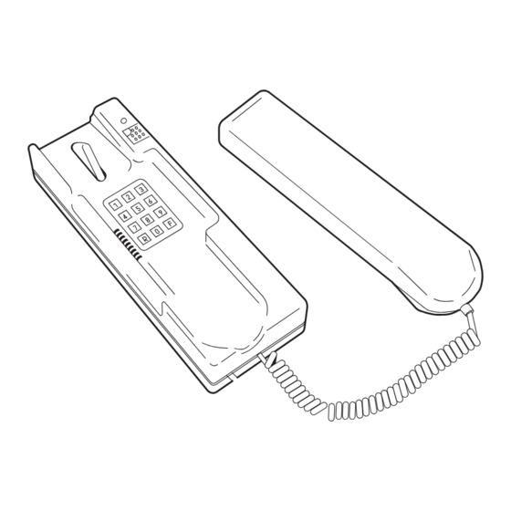
SYSTEM FEATURES - EQUIPMENT - INTERCOM DOOR PHONE FEATURES ELECTRONIC INTERCOM SYSTEM Mod. 926 EQUIPMENT Electronic intercom Mod. 926 can be installed in any building for The device forming part of the system are as follows: • Intercom door phone a simple and effi... -
Page 4: Push Button Panel And Amplified Loudspeaking Unit
ELECTRONIC INTERCOM SYSTEM Mod. 926 EASIVOICE EASIVOICE PUSH BUTTON PANEL AND AMPLIFIED LOUDSPEAKING UNIT - POWER SUPPLY Ref. 926/3 TABLE SET The connection cable wires to the door phone socket wire are very specifi c for table installations. They must be connected to the intercom... -
Page 5: Features
R = Redial F = Follow-me CLEARING THE LINE The key located on the upper right of Mod. 926/2 is used for opening Caller (only from authorized intercom door phones) the door. Other functions (clearing a line, general call) can only be Lift the handset and dial the number of the called party. -
Page 6: Conference Call
The maximum distance between the power supply and the furthest intercom must be less than 200 meters. This feature is only available on Ref. 926/2 intercom door phone. The maximum distance between two intercom door phones to ensure A call from the outdoor station produces a different acoustic signal from the normal one and can be easily recognized. -
Page 7: Wire Section
Call Station and can all answer a single call key. In this case, when there is a call, all 926/2 intercoms will ring at the same time. The fi rst intercom to answer will automatically exclude the other intercom, thus ensuring conversation privacy. -
Page 8: Intercom Connection Of Maximum 25 Intercom Door Phones
WIRES The power supply Ref. 926/3 is sized for an average installation of 25 intercoms. A larger number of intercoms will require additional power As indicated in Scheme SC101-0313E. - Page 9 COLLEGAMENTO INTERCOMUNICANTE DI UN MASSIMO DI EASIVOICE INTERCOM CONNECTION OF MAXIMUM 25 INTERCOM DOOR PHONES Possibility of general call service by means of loudspeakers SC101-0313E sec.2 −−−− DOOR PHONE - VIDEO DOOR PHONE SYSTEMS: Installation Diagrams...
-
Page 10: Possibility Of General Call Service By Means Of Loudspeakers
WIRES The power supply Ref. 926/3 is sized for an average installation of 25 intercoms. A larger number of intercoms will require additional power As indicated in Scheme SC101-0315E. - Page 11 INTERCOM CONNECTION OF MAXIMUM 97 INTERCOM DOOR PHONES EASIVOICE Possibility of general call service by means of loudspeakers SC101-0315E LINE~ sec.2 −−−− DOOR PHONE - VIDEO DOOR PHONE SYSTEMS: Installation Diagrams...
- Page 12 As indicated in Scheme SC101-0316G. 13 wires common to all the intercom door phones are necessary, 8 of which coming from the power supply Ref. 926/3 and 5 from the push button panel, power supply and relay. The electric lock will be released through the relay box Ref. 788/52.
- Page 13 INTERCOM CONNECTION OF MAXIMUM 16 INTERCOM DOOR PHONES EASIVOICE With possibility to answer to 1 outdoor station All the intercom door phones are called in parallel from the outdoor station SC101-0316G sec.2 −−−− DOOR PHONE - VIDEO DOOR PHONE SYSTEMS: Installation Diagrams...
-
Page 14: The Outdoor Station Is Equipped With Two Keys
As indicated in Scheme SC101-0361G. 12 wires common to all the intercom door phones are necessary, 8 of which coming from the power supply Ref. 926/3 and 4 from the push button panel, power supply and relay. Moreover from the push button panel two other wires, for calls, start;... -
Page 15: Intercom Connection Of Maximum 16 Intercom Door Phones With Possibility To Answer To 1 Outdoor Station
INTERCOM CONNECTION OF MAXIMUM 16 INTERCOM DOOR PHONES With possibility to answer to 1 outdoor station The intercoms are divided in two EASIVOICE groups of 8. The outdoor station is equipped with two keys: with one of them it calls in parallel the 8 intercoms of group I, with the second one those of group II SC101-0361G sec.2 −−−−... - Page 16 13+n 13 wires common to all the intercom door phones are necessary, 9 of which coming from the power supply Ref. 926/3 and 4 from the push button panel, power supply and relay. Moreover from the push button panel all single call wires start towards each intercom.
- Page 17 INTERCOM CONNECTION OF MAXIMUM 16 INTERCOM DOOR PHONES EASIVOICE With possibility to answer to 1 outdoor station. The intercoms are called separately from theoutdoor station. Possibility of paging service by means of loudspeakers SC101-0382F sec.2 −−−− DOOR PHONE - VIDEO DOOR PHONE SYSTEMS: Installation Diagrams...
- Page 18 EASIVOICE −−−− sec.2 DOOR PHONE - VIDEO DOOR PHONE SYSTEMS: Installation Diagrams...
Need help?
Do you have a question about the EASIVOICE 926 and is the answer not in the manual?
Questions and answers