
Related Manuals for urmet domus 1145/1


Summary of Contents for urmet domus 1145/1
- Page 1 Mod. 1145 DS1145-019A LBT8072 UNIVERSAL COMBIPHONE DOOR UNIT Ref. 1145/1 Ref. 1145/2 Ref. 1145/4 Ref. 1145/14 USER MANUAL...
-
Page 2: Table Of Contents
TABLE OF CONTENTS TABLE OF CONTENTS -------------------------------------------------------------------------------2 BASIC DESCRIPTION -------------------------------------------------------------------------3 CHARACTERISTICS------------------------------------------------------------------3 SYSTEM MODULES ------------------------------------------------------------------3 MODULES CHARACTERISTICS --------------------------------------------------4 1.3.1 Basic Module DEVICE COMPONENTS INSTALLATION---------------------------------------7 DEVICE OPERATIONS------------------------------------------------------------------------7 SIGNALS ---------------------------------------------------------------------------------7 COMBIPHONE DOOR UNIT --------------------------------------------------------8 2.2.1 Device CALLS-------------------------------------------------------------------------------------8 2.3.1 Outgoing Call 2.3.2 Incoming Call PARAMETERS PROGRAMMING-----------------------------------------------------------9 PROGRAMMING BY PHONE-------------------------------------------------------9 3.1.1... -
Page 3: Basic Description
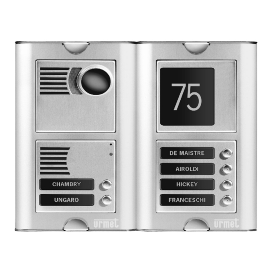
Always on back-lighting (with optional power supply) • Protection against static electricity SYSTEM MODULES The device structural elements are the basic modules with two (1145/2) or one (1145/1) button and the modules with four buttons (1145/4 and 1145/14) 1145/2 1145/1... -
Page 4: Modules Characteristics
Examples of frame configuration MODULES CHARACTERISTICS 1.3.1 Basic Module The basic module is supplied in two versions, with two buttons (1145/2) and with one button (1145/1). Programming jumper (in short Speaker volume circuit – without password) adjustment Microphone volume adjustment... - Page 5 Note: It is suggested not to connect the device to the extension lines that become emergency phones in case of mains failure and to disable the access to the extension telephone line to which the device will be connected. 1145/1-2 1145/1-2 For lighting and relay...
- Page 6 This module is available in two versions. The Ref.1145/4 module has four buttons and it is provided with the circuits used to connect it to the 1145/1-2 basic module or to a 1145/4 previous module. This module is connected only with the provided cable; buttons and relative lighting are already interconnected with this cable.
-
Page 7: Device Components Installation
DEVICE COMPONENTS INSTALLATION Wall installation By this installation, are only used the 1145/5X compact box and 1145/3XX cover to protect the device against the rain. It replaces all the mechanical parts. To install the device screw on the box to the wall with pins, as shown in the figure. -
Page 8: Combiphone Door Unit
COMBIPHONE DOOR UNIT The universal device depends on the used modules and on the parameters programming (see “Environment control parameters” chapter). 2.2.1 Device Device buttons are provided with name holder tags or person positions inside the building. The visitor will press the button corresponding with the desired apartment;... -
Page 9: Parameters Programming
PARAMETERS PROGRAMMING PROGRAMMING BY PHONE 3.1.1 Access to programming The device can be configured in programming mode in two ways: By password – pick up the handset and dial the number of the extension line which the device is connected to. The device will answer (the answer tone will be emitted – see 2.1 section); within 10 seconds dial #xxxx. -
Page 10: Parameters Description
PARAMETERS DESCRIPTION DIRECT DIALLING – MEMORIES Parameter Value Meaning Basic Ex.1 Ex.2 tt nn… No. nn under button tt Button number (memory), always composed by two digits [01-64] Dialling choice Phone number to be stored, up to 16 digits. To save other selections, use the table. -
Page 11: Basic Parameters
Parameter Value Meaning Basic Ex.1 Ex.2 command aa from the phone r aa 155 266 155 266 155 266 for relay r relay number [1-2] command from phone for relay closing/opening (2 digits). The same command can be configured for both relays, that will be activated at the same time. It is very useful to configure the same command both for the relay opening and for device hanging up (parameter 43) aa=bb. -
Page 12: Time Parameters
Parameter Value Meaning Basic Ex.1 Ex.2 command to end the call g bb 134 235 155 244 155 244 from the phone command order [1-2] (two commands for hanging up with the device by using both relays) command to end the device call from the phone [2 digits] List of related parameters: 35 8# 84 Parameter Value... - Page 13 Parameter Value Meaning Basic Ex.1 Ex.2 call maximum duration time [min] value max. time, after which the device hangs up. This value can be increased during the call with the phone (* or #). Time configuration is shown in 1 - 9 1 - 9 the table.
-
Page 14: Presetting And Deleting
DTMF tone duration is determined by the formula: (entered number + 5) x 10 = tone duration [ms] [from 1 to 0, for ex. 60-150ms] Duration difference between DTMF tones is determined by the formula: (entered number + 5) x 10 = duration difference [ms] [from 1 to 0, for ex. -
Page 15: Parameters
PARAMETERS Parameter Value Meaning Basic Ex.1 Ex.2 tt nn… No. nn under button tt tt nn… No. nn under button tt switch r works in m mode 11 21 11 22 11 25 command aa from the phone for r aa 155 266 155 266 relay r closing... - Page 16 configuration for ex. 1 executes configuration for ex. 2 executes deleting all numbers of group 1(Day mode) deleting all numbers of group 2(Night mode) basic configuration only 3.. for parameters 3x only basic configuration only 4.. for parameters 4x only basic configuration only 5..
-
Page 17: Presetting Parameters List
PRESETTING PARAMETERS LIST parameter value Ex. 1 Ex. 2 Switch 1 mode lock m=1 lock m=1 lock m=1 Switch 2 mode lock m=1 camera m=2 prog. m=5 Switch 1 activ. from phone Switch 2 activ. from phone Closing time between switch 1 and 2 5 sec 2 sec 5 sec... -
Page 18: Technical Parameters
TECHNICAL PARAMETERS ELECTRICAL PARAMETERS Parameter Value Conditions Minimum current on the line 18mA On line Minimum voltage on the line hung up Line voltage while the device answers (VA < 8V I = 20mA characteristics) < 12V I = 60 mA Standby mode current <... -
Page 19: Mechanical Dimensions
MECHANICAL DIMENSIONS Dimensions HxWxD [mm] Type of item 1 module 2 modules 3 modules 4 modules 1145/5X Flush-mounting 114x118x45 204x118x45 294x118x45 384x118x45 1145/6X Module holder frame 119x125x12.6 209x125x12.6 299x125x12.6 389x125x12.6 1145/31X 1 column rain protective cover (wall 151x157x79 241x157x79 331x157x79 421x157x79 mounting) 1145/32X 2 columns rain... -
Page 20: Table For Easy Programming
TABLE FOR EASY PROGRAMMING Fill in the table with the values to be programmed. In the part with the double frame there are commands for the whole programming, that will be easy and without errors. Besides these programmed values will be available on the manual for future modifications. - Page 21 Number under button 5 Night/2gr. Number under button 6 Night/2gr. Number under button 7 Night/2gr. Number under button 8 Night/2gr. Number under button 9 Night/2gr. Number under button 10 Night/2gr. Number under button 11 Night/2gr. Number under button 12 Night/2gr. Switch 1 operates in mode m=1 - 4 Switch 2 operates in mode...
- Page 22 Device call ending from phone Device call ending from phone Service password Command for DAY mode switching Command for NIGHT mode switching Device selection mode 1 / 0 Rings number for the call Maximum conversation [min] time Time between button [sec] pressing.
-
Page 23: Wiring Example
WIRING EXAMPLE SC104-0076 DS1145-019A... - Page 24 DS1145-019A LBT8072 FILIALI STABILIMENTO 20151 MILANO – V.Gallarate 218 Tel. 02.380.111.75 - Fax 02.380.111.80 URMET DOMUS S.p.A. 00043 CIAMPINO (ROMA) V.L.Einaudi 17/19A 10154 TORINO (ITALY) Tel. 06.791.07.30 - Fax 06.791.48.97 VIA BOLOGNA 188/C 80013 CASALNUOVO (NA) V.Nazionale delle Puglie 3 Telef.
Need help?
Do you have a question about the 1145/1 and is the answer not in the manual?
Questions and answers