Sign In
Upload
Download
Table of Contents
Contents
Add to my manuals
Delete from my manuals
Share
URL of this page:
HTML Link:
Bookmark this page
Add
Manual will be automatically added to "My Manuals"
Print this page
×
Bookmark added
×
Added to my manuals
Manuals
Brands
Memmert Manuals
Oven
VO200
Operating instructions manual
Memmert VO200 Operating Instructions Manual
Vacuum drying oven, pump module
Hide thumbs
1
Table Of Contents
2
3
4
5
6
7
8
9
10
11
12
13
14
15
16
17
18
19
20
21
22
23
24
25
26
27
28
29
30
31
32
33
34
35
36
37
38
39
40
41
42
43
44
45
46
47
48
49
50
51
52
53
54
55
56
page
of
56
Go
/
56
Contents
Table of Contents
Bookmarks
Table of Contents
Operating Instructions
1 Contents
Table of Contents
2 General Notes and Safety Notes
Material Quality from MEMMERT
Transport
Initial Start-Up
Oven Load
Safety Check
3 Technical Data
Standard Equipment of VO-Ovens
Electrical Equipment
External Connection
4 Installation Facilities (Accessories)
Subframe
Stackable Version
5 Oven Construction and Connections
6 Starting up
7 Switching Output for External Vacuum Pump Purge Valve and Pump Control
Vacuum Pump Purge Valve
Demand-Controlled Vacuum Pump Shut-Down
8 Loading and Inertgas
9 Guidelines for Evaporating Liquids in Memmert-Vacuum Ovens
10 Controls and Indications
11 Operating the Door
12 Switching on
13 Setting the Temperature
14 Quick Venting Function
15 Status Indication for the Heating Levels
16 Selecting the Operating Mode
17 Setting the Parameters
Print
18 Normal Operation
Setting Example "Normal Operation
19 Weekly Programmer
Programming Example "Weekly Programmer
20 Programme Operation
Closure Commands for Ramp Segments
Programming Example Programme Operation
Printer PRINT
Setup
21 Printer
Real-Time Clock
22 Basic Oven Settings
23 Temperature Monitor and Protection Devices
Mechanical Temperature Monitor: Temperature Limiter (TB)
Electronic Temperature Monitor
Overtemperature Protection MAX
Undertemperature Protection MIN
Adjustable Temperature Monitor (TWW) Protection Class 3.1 to DIN 12 880
Adjustable Temperature Limiter (TWB) Protection Class 2 to DIN 12 880
Automatic Temperature Monitor (ASF) AUTO
Basic Oven Settings SETUP
24 Calibration
Calibration-Temperature
Calibration-Pressure (Vacuum)
25 Communication Interface for the PC
Communication Interface RS232C
Bus Interface RS485
26 Report Memory
Reading the Report Memory
Reading the Report Memory into the PC Via RS232C
Printing the Report Memory from the Oven
27 Memory Card: Memorycardxl
Programming the Memorycardxl from the Oven
Programming the Memorycardxl from a PC with the Oven
Programming the Memorycardxl from a PC Using the Read-Write Unit
Documentation on Memory Card Memorycardxl
28 USER-Idcard (Available as Optional Extra)
29 Cleaning
30 Maintenance
31 Door Seal
32 Error Messages
33 Supply Failure
34 CE Conformity Declaration
35 Address and Customer Service
36 Index
Advertisement
Quick Links
1
Controls and Indications
2
Setting the Temperature
Download this manual
VO
Operating Instructions
Tu
Sa
Su
Mo
We
Th
Fr
on
t1
off
t3
STERI
4
t2
t4
3
loop
2
1
PRINT
SETUP
set
push
card
on
off
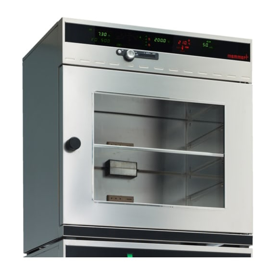
VO
Vacuum Drying Oven
VO200 / VO400 / VO500
Pump Module
PM200 / PM400 / PM500
DEFRO
IN 1
°C
°C
MAX
MIN
AUTO
page 1
IN 2
OUT
IN 1
IN 2
OUT
rh
CO
%
2
mb
mb
PERFECT
Table of
Contents
Previous
Page
Next
Page
1
2
3
4
5
Advertisement
Table of Contents
Need help?
Do you have a question about the VO200 and is the answer not in the manual?
Ask a question
Questions and answers
Related Manuals for Memmert VO200
Vacuum Cleaner Memmert VO COOL 200 Operating Instructions Manual
Vacuum oven with peltier cooling (56 pages)
Oven Memmert VO500 Operating Instructions Manual
Vacuum drying oven, pump module (56 pages)
Oven Memmert VO400 Operating Instructions Manual
Vacuum drying oven, pump module (56 pages)
Oven Memmert VO Series Operating Manual
Vacuum oven (68 pages)
Oven Memmert VO Series Operating Manual
Vacuum oven (64 pages)
Oven Memmert UE 200 Operating Instructions Manual
Electronically controlled drying ovens/electronically controlled sterilisers/electronically controlled incubators (36 pages)
Oven Memmert UE200 Operating Instructions Manual
Electronically controlled ovens (11 pages)
Oven Memmert UN PLUS Operating Instructions Manual
Universal oven (60 pages)
Oven Memmert UN Operating Instructions Manual
Universal oven, incubator, steriliser (48 pages)
Oven Memmert UE 200 Operating Instructions Manual
Electronically controlled ovens (10 pages)
Oven Memmert UN PLUS Series Operating Instructions Manual
(60 pages)
Oven Memmert BASIC Service Instructions Manual
(36 pages)
Oven Memmert UNE 200 Operating Instructions Manual
(44 pages)
Oven Memmert SN Series Operating Instructions Manual
(48 pages)
Oven Memmert SF Series Operating Instructions Manual
(56 pages)
Oven Memmert UN Series Quick Manual
Universal oven u incubator i (29 pages)
This manual is also suitable for:
Vo500
Pm200
Vo400
Pm400
Pm500
Table of Contents
Save PDF
Print
Rename the bookmark
Delete bookmark?
Delete from my manuals?
Login
Sign In
OR
Sign in with Facebook
Sign in with Google
Upload manual
Upload from disk
Upload from URL


Need help?
Do you have a question about the VO200 and is the answer not in the manual?
Questions and answers