Table of Contents
Advertisement
Advertisement
Table of Contents

Related Manuals for Topcon RL-100 2S


Summary of Contents for Topcon RL-100 2S
- Page 1 INSTRUCTION MANUAL ROTATING LASER RL-100 2S 31485 90050...
-
Page 2: Declaration Of Conformity
“The installer of this radio equipment must ensure that the antenna is located or pointed such that it does not emit RF field in excess of Health Canada limits for the general population; consult Safety Code 6, obtainable from Health Canada’s website www.hc-sc.gc.ca/rpb”. Declaration of Conformity Model Number: RL-100 2S/RC-400 Trade Name: TOPCON CORPORATION Responsible party: TOPCON POSITIONING SYSTEMS,Inc. -
Page 3: Foreword
Thank you for purchasing the Topcon RL-100 2S Rotating Laser. It is one the world’s most advanced and accurate grade-setting lasers. To quickly and effectively use the RL-100 2S, please read these brief instructions carefully, and keep them in a convenient location for future reference. -
Page 4: Safety Information
Safety Information In order to encourage the safe use of products and prevent any danger to the operator and others or damage to properties, important warnings are put on the products and inserted in the instruction manuals. We suggest that everyone understand the meaning of the following displays and icons before reading the “Safety Cautions”... -
Page 5: Safety Cautions
There is a risk of fire, electric shock or physical harm if you attempt to disassemble or repair the instrument yourself. This is only to be carried out by TOPCON or an authorized dealer, only! Laser beams can be dangerous, and can cause eye injury if used incorrectly . - Page 6 CAUTION Use of controls or adjustment or performance of procedures other than those specified herein may result in hazardous radiation exposure. Do not connect or disconnect equipment with wet hands, you are at risk of electric shocks if you do! Risk of injury by overturn the carrying case.
-
Page 7: Exceptions From Responsibility
EXCEPTIONS FROM RESPONSIBILITY 1) The user of this product is expected to follow all operating instructions and make periodic checks of the product’s performance. 2) The manufacturer, or its representatives, assumes no responsibility for results of a faulty or intentional usage or misuse including any direct, indirect, consequential damage, and loss of profits. -
Page 8: Laser Safety
Do not disassemble the instrument or attempt to perform any internal servicing. Repair and servicing of this laser are to be performed by TOPCON or its authorized dealer. Caution : Use of adjustment controls or performance procedures other than those specified herein may result in hazardous radiation exposure. -
Page 9: Table Of Contents
Contents ........................7 Standard System Components.................. 9 Nomenclature......................... 10 Sample Display......................12 Key Functions ......................13 RL-100 2S LED Display ................... 13 Basic Operation......................14 Preparation and Functions ..................... 15 Power Source ......................15 Setting Up Instrument ....................15 RC-400 Remote Controller ..................16 Power Switch ...................... - Page 10 Maintaining Power Sources ................... 33 How to Change Batteries on the Instrument............33 How to Replace the RC-400 Batteries ..............37 Check and Adjusting ...................... 38 Horizontal Calibration ....................38 Horizontal Rotation Cone Error................42 Grade Setting Error....................43 Storage Precautions....................... 45 Standard/Optional Accessories..................
-
Page 11: Standard System Components
Standard System Components Instrument ...............1pc. Level sensor LS-80B ..........1pc. Remote controller RC-400........1pc. Level sensor holder model 6 ........1pc. Carrying case ............1pc. AA Manganese battery (To confirm operation)*..5pcs. Instruction manual ..........1vol. Battery holder DB-67C ..........1pc. Ni-MH battery pack BT-67Q ........1pc. 10) AC/DC converter AD-11 ..........1pc. •... -
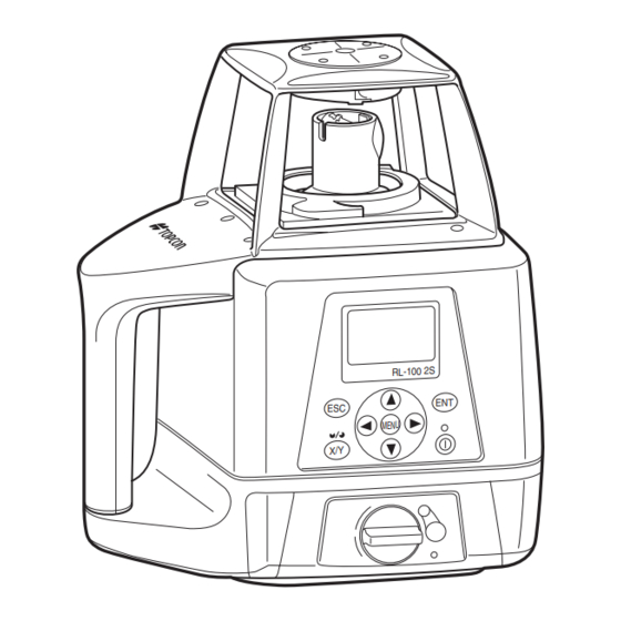
Page 12: Nomenclature
Nomenclature Rotary head/Laser emitting window Beam aperture RC-400 Remote Controller Display Display Escape key Enter key Arrow keys MENU key Handle Power X/Y key switch Control panel Battery compartment lock Battery holder DB-67C... - Page 13 Control panel MENU key Escape key Enter key RL-100 2S Automatic leveling indicator X/Y key MENU Power switch Arrow keys...
-
Page 14: Sample Display
Sample Display Normal display X axis grade (Blinks digit by digit during leveling) Y axis grade (Blinks digit by digit during leveling) Leveling indicator (Blinks during leveling) Transmission and Rotation speed (rpm) Channel reception display (On remote controller only) Battery remaining Rotating laser display: Transmitting Remote controller display: RC... -
Page 15: Key Functions
Inputs the grades of X Y axis. Sets the masking direction. Power switch On/Off of the RL-100 2S and RC-400. (RC-400 has auto-cut off 60 seconds function) RL-100 2S LED Display There is an LED that signals automatic alignment of the control panel screen of the main instrument. -
Page 16: Basic Operation
Basic Operation Set the instrument on a tripod or smooth surface and turn on the power. When using the remote controller, turn on the power for the instrument, and then the power for the remote controller. Set X and/or Y axis grades. Turn on the level sensor. -
Page 17: Preparation And Functions
Preparation and Functions Power Source Connect the battery according to the battery type purchased. For charging and battery replacement instructions, see the “Maintaining Power sources” section. Setting Up Instrument Set the instrument on a tripod or smooth surface. The instrument must be within horizontal ±5 degrees of true level for auto-leveling to operate. -
Page 18: Rc-400 Remote Controller
RC-400 Remote Controller When using the remote controller, turn on the power for the instrument, and then the power for the remote controller. Key operation Press the [ENT] key after each key operation to lock the entry. There will be interactive transmission between the instrument and the remote controller. - Page 19 RC-400 remote controller can control plural RL-100 2S. When you are using plural RL-100 2S at your job site, you can use your RC-400 for the other RL-100 2S unit. Change the channel to receive the internal data of each RL-100 2S to the RC-400 by operating the RC-400.
-
Page 20: Power Switch
Power Switch When the power switch on the instrument is turned on, automatic alignment and automatic grade setting will activate. When using the RC-400 for wireless remote control, also turn the instrument ON or OFF by pressing the power switch on the RC-400. When transmission had not been correctly performed, “NG”... - Page 21 The channel on the RL-100 2S is not same as one on the RC-400 (Remote mode). If the channel on the main unit is different from that on the remote control when the power switch is turned ON, the channel on the main unit will be automatically searched for.
-
Page 22: Battery Status Display
Rotating laser display: Remote controller display: RC RL-100 BATTERY Low Dead batteries of RL-100 2S or RC-400. Recharge the battery or replace the dry batteries with new ones. RC-400 BATTERY Low (Displayed on the RC-400 only) -
Page 23: Setting Grades
Setting Grades Grade can be set in both axes, X and Y, as shown below. Grades can be set in the range indicated below. X: –10% to +10% Y: –5% to +25% Grade axes and axis symbols are as shown in the diagram below. +10% +25% X axis... -
Page 24: Aligning Direction Of Grade
Aligning Direction of Grade When using the laser with a percent of grade entered, the laser must be properly aligned so the slope of the laser beam is parallel to the desired direction of grade. The sighting collimator on top of the instrument is calibrated to the grade axis of the laser beam. -
Page 25: How To Enter Grade
Single axis Dual axes X axis Y axis Grade range: X: –10% to +10% Grade range: X: –10% to +10% Y: –5% to +25% Y: –5% to +25% How to Enter Grade Press the X/Y key to begin grade input. The axis symbol will flash and it will go into grade entry X axis status. -
Page 26: Menu
Menu How to Set the Menu As indicated by arrows in the figure, there are 6 setting categories in the menu and selection and changes of the settings are performed using the arrow keys and [ENT] key. Press the menu key to display the menu screen. As Changing Masking Mode you can see, the mask setting is framed with the Changing rotary head speed... - Page 27 The menu allows setting of the following functions. 1) Changing Masking Mode 2) Changing rotary head speed 3) Setting channel 4) Sensitivity Level (LEVEL) 5) Safety Lock System (Height Alert) 6) Alarm Signal (COM) 1) Changing Masking Mode Sets up masking (laser beam shut off) and change shut off directions. Masking (Laser beam shutter) setting Depending on the status of the location where the instruments are used, laser beam emission to unnecessary direction can be shut off.
-
Page 28: Switching Masking Mode
When setting up using the remote Displays the masking direction controller After completing 1 through 4 of the above Displays the direction that laser beam is emitted. setting procedures, check that the transmission and reception display is showing “OK”. The status in which the X+ direction is masked. If the [NG] mark is displayed, press [ENT] (Laser beam is shut off in the X+ direction.) again. - Page 29 Masking Mode Setting Follow steps 1-2 for the masking setting. Each press of the [X] or [Y] key toggles Mask Mode 1 and Mask Mode 2. Press the [ENT] key to lock the entry. When setting up with the remote controller, make sure that “OK”...
- Page 30 “How to set the menu”, press the [ENT] key to lock entry. Search for the channels available on active or standby RL-100 2S. When the search is completed, searched channels will be displayed. Use the arrow keys (up and down) to position the curser on the channel you want to select and then press the [ENT] key.
- Page 31 4) Sensitivity Level (LEVEL) The sensitivity level allows the user to select the vibration level that is permitted during automatic alignment or grade setting. Set a sensitivity level to suit the location where the instrument is used such as places that undergo many vibrations, and also in consideration of the operational precision.
- Page 32 5) Safety Lock System (Height Alert) In case the [ALERT] setting is ON. Safety Lock System will active. (This will be active around 10 minutes after turning on the power.) Should the installed status of the instrument suddenly change when automatic alignment is functioning and laser beam is being emitted, through, for example, unnecessary contact by the user, the automatic alignment function will automatically stop to protect operational precision.
- Page 33 6) Alarm Signal (COM) When used with the Topcon laser sensor, the RL-100 2S can communicate alarm signals directly to the sensor. This helps enable the user to be completely aware of potential problems before they can become serious. Active...
- Page 34 Concerning initial operation in a low temperature When the instrument and remote controller is used in a temperature below -10°C, a warm up operation of approximately 4 minutes is necessary for the LCD after the power is turned on. During the warm up operation, no operation is possible except turning the power switch on/off. The instrument will perform automatic alignment;...
-
Page 35: Maintaining Power Sources
Maintaining Power Sources How to Change Batteries on the Instrument Dry battery How to replace dry batteries Remove the battery cover by turning the battery cover knob to “OPEN”. Remove the old batteries and replace with new batteries (four D batteries) matching [+] and [-] as shown in the figure. -
Page 36: Rechargeable Battery
Rechargeable battery Installing 1 Insert Ni-MH BT-67Q battery pack into the DB-67C battery holder. 2 Insert the battery pack into the instrument and turn the battery cover knob to “LOCK”. Charging 1 Plug the AC/DC converter AD-11 into the DB-67C battery holder. - Page 37 Red flashing : Ni-MH BT-67Q battery pack protection feature is working automatically. RL-100 2S can be used in this state. The instrument has a protection feature which works when nickel hydride batteries are overcharged or when the batteries are under a high or low temperature (+70°C or higher, or 0°C or lower) state.
- Page 38 1) For longer battery life, conform to the suggested charging time to the extent possible. 2) The battery source will discharge when stored and should be checked before using with instrument. 3) Be sure to charge stored battery source every 3 or 6 months and store in a place at 30 °C or below.
-
Page 39: How To Replace The Rc-400 Batteries
How to Replace the RC-400 Batteries Keep pushing the battery cover in [1] direction, and then try to slide the cover in [2] direction. The cover does not move but it will be open. Remove the old batteries and replace with new batteries (three AA batteries), matching [+] and [-] as shown in the figure. -
Page 40: Check And Adjusting
Check and Adjusting Horizontal Calibration (1) Checking Calibration 1 Steadily set up a tripod approximately 50m from a staff member or wall and adjust so that the head 50m (164feet) of the tripod is horizontal. Mount the instrument on the tripod in the direction shown in the right figure (Y-axis facing the wall). - Page 41 (Example: Y axis) 4 Select Y axis by pressing the right arrow key. Press the [ENT] key to lock. 5 “POSITION 1” display will flash and the instrument POSITION 1 will begin automatic alignment. After the automatic alignment is completed, the “POSITION 1” light will turn on, then, the rotary head rotates and emits Check the laser beam on the wall.
- Page 42 9 Loosen the tripod and rotate the instrument 180° Check the misalignment of laser beam of (Y+) and (Y-) on the wall. and retighten to fix. The Y+ side of the instrument should be facing the wall. After the automatic If one of the 3 center indicators is lit, calibration is normal.
- Page 43 The screen goes back to the axis selection screen. If the correction value calculated exceeds the allowable range, the RL-100 2S will display error code [CALIBRATION OVER ERR]. Check the procedure again and perform any inspections and adjustments.
-
Page 44: Horizontal Rotation Cone Error
6 If the difference between each set of marks is less than ±5 mm (±7/32 of an inch), no error exists. If the difference between [wall A]-side and [wall B]-side exceeds ±5 mm (±7/32 of an inch), contact your dealer or Topcon. -
Page 45: Grade Setting Error
Grade Setting Error Perform the following check only after completing “Horizontal Calibration” and “Horizontal Rotation Cone Error”. (1) Checking 1 Setup the Y+ side facing the staff as shown in the figure. Staff Level sensor Nail 1 Nail 2 Securely position Nail 1 and Nail 2 exactly 30m apart. 2 Turn on power for the instrument and verify the staff height of Nail 1 and Nail 2 at grade setting of 0% with laser sensor and record. - Page 46 If the calculated result is the range of 0.990% - 1.010%, the instrument is normal. If the calculated result for either axis is out of the range, contact your dealer or Topcon. Repeat the procedure aligning the “X” axis on the line created by Nail 1 and Nail 2.
-
Page 47: Storage Precautions
Storage Precautions (1) Always clean the instrument after use. 1) If the instrument got wet with rain, wipe it well before storing in the storage case. 2) Wipe away stain or dirt with soft cloth after dusting. (2) Clean storage case using cloth moistened with neutral detergent or water. Do not use ether, benzene, thinner or other solvents. -
Page 48: Standard/Optional Accessories
Standard/Optional Accessories Level sensor holder model 6 1 5 4 1 5 3 1 5 2 1 5 1 1 5 0 1 4 9 Clamp knob 1 4 8 1 4 7 1 4 6 H O L D E R -6 1 3 1 1 3 9 1 3 8... - Page 49 Level Sensor LS-80A / 80B Power switch Display Display (Only LS-80A) Detective precision switch Two leveling precision Index options are available, normal precision and high precision. By pressing this switch, the precision options are Beam receiving switched alternately. Confirm window the precision choice by the indicator.
- Page 50 No audio signal is generated for this warning. The warning signal *1 and *2 will function only if RL-100 2S Alert Signal function [COM] is active. Alarm detection at the level sensor can be canceled by turning off the level sensor switch while pressing the buzzer sound switch.
- Page 51 Detective Replacing Battery Mode HIGH NORMAL Display range ±1 mm/±.0032 ft ±2 mm/±.0064 ft (2 mm/.0064 ft width) (4 mm/.013 ft width) ±5 mm/±.016 ft (10 mm/.032 ft width) 1 Keep pushing the battery lid in [1] direction, and then try to slide the lid in [2] direction to lift.
- Page 52 Scope Model 4 The optional scope replaces the sighting collimator (see page 22) on top of the instrument and provides greater accuracy in aligning the laser to the direction of grade. The scope can be swiveled and locked in place so its aimed toward any of the four beam axes. Using the scope, follow the steps on page 22 to align the instrument.
-
Page 53: Specifications
Specifications RL-100 2S Accuracy (reproducibility) : ±10" Auto-leveling range : ±5° Measuring range (Diameter) : Approx. 2 – 800 m (6 - 2624.7 ft) with level sensor Rotation speeds : 300/600/900 rpm (Changeable) Light source : L.D (Visible laser) Power supply : 4D-CELL dry batteries (DC6V) Ni-MH battery pack BT-67Q (It can be charged while using it.) - Page 54 LS-80A (Back side display area) LS-80B Detective range : 50 mm (2.0 in) Detective range : 50 mm (2.0 in) Detective precision Detective precision High precision : ±1 mm (±0.04 in) High precision : ±1 mm (±0.04 in) Normal precision : ±2 mm (±0.08 in) Normal precision : ±2 mm (±0.08 in) Detective beam indication Detective beam indication...
-
Page 55: Error Display
Error Display Error Code Description Countermeasure Batteries of the instrument are Replace the batteries of the instrument. dead. RL-100 BATTERY LOW Batteries of the remote controller Replace the batteries of the remote controller. are dead. RC-400 BATTERY LOW Turn the power for the instrument off, and then turn it Safety lock system is activated. - Page 56 Turn the power for the instrument off, and then turn it E-99 instrument back on. Turn the power for the instrument off, and then turn it LCD backlight is Cannot be displayed back on. flashing If errors still persist after attempting to clear them, contact Topcon or your dealer.
-
Page 57: Fcc Warning
FCC WARNING This device complies with Part 15 of the FCC Rules. Operation is subject to the following two conditions: (1) this device may not cause harmful interference, and (2) this device must accept any interference received, including interference that may cause undesired operation. -
Page 58: Ic Warning
IC WARNING The term “IC:” before the radio certification number only signifies that Industry Canada technical specifications were met. “Operation is subject to the following two conditions: (1) this device may not cause interference, and (2) this device must accept any interference, including interference that may cause undesired operation of the device.”... - Page 60 7400 National Drive, Livermore, CA 94550, U.S.A. Topcon House Kennet Side, Bone Lane, Newbury, Berkshire RG14 5PX U.K. Phone: 925-245-8300 Fax: 925-245-8599 www.topcon.com Phone: 44-1635-551120 Fax: 44-1635-551170 survey.sales@topcon.co.uk laser.sales@topcon.co.uk 3380 Industrial Blvd, Suite 105, West Sacramento, CA 95691, U.S.A. Phone: 916-374-8575 Fax: 916-374-8329 Blk 192 Pandan Loop, #07-01 Pantech Industrial Complex, Singapore 128381 Phone: 65-62780222 Fax: 65-62733540 www.topcon.com.sg...
Need help?
Do you have a question about the RL-100 2S and is the answer not in the manual?
Questions and answers