Table of Contents
Advertisement
Advertisement
Table of Contents

Related Manuals for Topcon RL-200 2S


Summary of Contents for Topcon RL-200 2S
- Page 1 INSTRUCTION MANUAL ROTATING LASER RL-200 2S 31492 90030...
-
Page 3: Foreword
Thank you for purchasing the Topcon RL-200 2S Rotating Laser. It is one the world’s most advanced and accurate grade-setting lasers. To quickly and effectively use the RL-200 2S, please read these brief instructions carefully, and keep them in a convenient location for future reference. -
Page 4: Precautions For Safe Operation
Precautions for Safe Operation For the safe use of the product and prevention of injury to operators and other persons as well as prevention of property damage, items which should be observed are indicated by an exclamation point within a triangle used with WARNING and CAUTION statements in this instruction manual. The definitions of the indications are listed below. - Page 5 General Warning Do not perform disassembly or rebuilding. Fire, electric shock or burns could result. Do not use the unit in areas exposed to high amounts of dust or ash, in areas where there is inadequate ventilation, or near combustible materials. An explosion could occur.
-
Page 6: Power Supply
Power Supply Warning Do not short circuit. Heat or ignition could result. Do not use voltage other than the specified power supply voltage. Fire or electrical shock could result. Do not use damaged power cords, plugs or loose outlets. Fire or electric shock could result. - Page 7 Do not use the battery or charger for any other equipment or purpose. Fire or burns caused by ignition could result. To prevent shorting of the battery in storage, apply insulating tape or equivalent to the terminals. Otherwise shorting could occur, resulting in fire or burns. Do not use batteries or the battery charger if wet.
- Page 8 Tripod Caution When mounting the instrument to the tripod, tighten the centering screw securely. Failure to tighten the screw properly could result in the instrument falling off the tripod, causing injury. Tighten securely the leg fixing screws of the tripod on which the instrument is mounted.
-
Page 9: User
User Wear the required protectors (safety shoes, helmet, etc.) when operating. Exceptions from Responsibility • The user of this product is expected to follow all operating instructions and make periodic checks of the product’s performance. • The manufacturer, or its representatives, assumes no responsibility for results of a faulty or intentional usage or misuse including any direct, indirect, consequential damage, and loss of profits. -
Page 10: Laser Safety Information
Laser Safety Information The RL-200 2S is classified as a class 3R Laser Product according to IEC Standard Publication 60825-1 Ed.2.0: 2007 and United States Government Code of Federal Regulation FDA CDRH 21CFR Part1040.10 and 1040.11 (Complies with FDA performance standards for laser products except for deviations pursuant to Laser Notice No.50, dated June 24, 2007.) - Page 11 Visible laser Laser output: 2.5mW Beam aperture LASER RADIATION AVOID DIRECT EYE EXPOSURE WAVE LENGTH 685nm 5mW MAXIMUM OUTPUT CLASS LASER PRODUCT Explanatory Label Each label is differed by the market. Warning • Use of controls or adjustments or performance of procedures other than those specified herein may result in hazardous radiation exposure.
- Page 12 • Never intentionally point the laser beam at another person. The laser beam is injurious to the eyes and skin. • Do not look directly into the laser beam. Doing so could cause permanent eye damage. • Do not stare at the laser beam. Doing so could cause permanent eye damage. •...
- Page 13 • Only those who have received training as per the following items shall use this product. • Read the manual for usage procedures for this product. • Hazardous protection procedures (read "Laser Safety Information") • Requisite protective gear (read "Laser Safety Information") •...
-
Page 14: Standard System Components
Standard System Components Rechargeable battery type Dry battery type 1) Instrument............ 1pc. 1) Instrument ............ 1pc. 2) Remote controller RC-400......1pc. 2) Level Sensor LS-80L ........1pc. 3) Level Sensor LS-80L ........1pc. 3) Level Sensor Holder Model-6 ...... 1pc. 4) Level Sensor Holder Model-6 ...... -
Page 15: Table Of Contents
Exceptions from Responsibility ....................7 Laser Safety Information ......................8 Standard System Components ....................12 Contents............................13 Nomenclature..........................15 Sample Display ........................17 Key Functions ........................18 RL-200 2S LED Display ......................18 Basic Operation...........................19 Preparation and Functions ......................20 Power Source.........................20 Setting Up Instrument ......................20 RC-400 Remote Controller.....................21 Power Switch .........................23 Battery Status Display......................25... - Page 16 How to Set the Menu......................29 Maintaining Power Sources ......................37 How to Change Batteries on the Instrument ................37 How to Replace the RC-400 Batteries ...................41 Check and Adjusting ........................42 Horizontal Calibration......................42 Horizontal Rotation Cone Error ....................46 Grade Setting Error ........................47 Storage Precautions........................49 Standard Accessories .........................50 Specifications ..........................55 Error Display ..........................57...
-
Page 17: Nomenclature
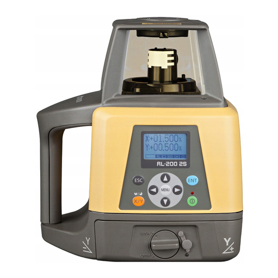
Nomenclature Rotary head/Laser emitting window Beam aperture RC-400 Remote Controller Display Display Escape key Enter key Arrow keys MENU key Handle Power X/Y key switch Control panel Battery compartment lock Battery holder... - Page 18 Control panel MENU key Escape key Enter key Auto-leveling indicator X/Y key MENU Power switch Arrow keys...
-
Page 19: Sample Display
Sample Display Normal display X axis grade (Blinks digit by digit during leveling) Y axis grade (Blinks digit by digit during leveling) Auto-leveling indicator (Blinks during leveling) Transmission and Rotation speed (rpm) Channel reception display (On remote controller only) Battery remaining Rotating laser display: Transmitting Remote controller display: RC... -
Page 20: Key Functions
Inputs the grades of X Y axis. Sets the masking direction. Power switch On/Off of the RL-200 2S and RC-400. (RC-400 has auto-cut off 60 seconds function) RL-200 2S LED Display There is an LED that signals auto-leveling of the control panel screen of the main instrument. -
Page 21: Basic Operation
Basic Operation Set the instrument on a tripod or smooth surface and turn on the power. When using the remote controller, turn on the power for the instrument, and then the power for the remote controller. Set X and/or Y axis grades. Turn on the level sensor. -
Page 22: Preparation And Functions
Preparation and Functions Power Source Connect the battery according to the battery type purchased. For charging and battery replacement instructions, see the “Maintaining Power Sources” on page 37 section. Setting Up Instrument Set the instrument on a tripod or smooth surface. The instrument must be within horizontal ±5 degrees of true level for auto-leveling to operate. -
Page 23: Rc-400 Remote Controller
RC-400 Remote Controller When using the remote controller, turn on the power for the instrument, and then the power for the remote controller. Key operation Press the [ENT] key after each key operation to lock the entry. There will be interactive transmission between the instrument and the remote controller. - Page 24 RC-400 remote controller can control plural RL-200 2S. When you are using plural RL-200 2S at your job site, you can use your RC-400 for the other RL-200 2S unit. Change the channel to receive the internal data of each RL-200 2S to the RC-400 by operating the RC-400.
-
Page 25: Power Switch
Power Switch When the power switch on the instrument is turned on, auto-leveling and automatic grade setting will activate. When using the RC-400 for wireless remote control, also turn the instrument ON or OFF by pressing the power switch on the RC-400. When transmission had not been correctly performed, “NG”... - Page 26 The channel on the RL-200 2S is not same as one on the RC-400. If the channel on the main unit is different from that on the remote control when the power switch is turned ON, the channel on the main unit will be automatically searched for.
-
Page 27: Battery Status Display
Remote controller display: RC (Indication continues until batteries are dead.) RL BATTERY LOW : Dead batteries of RL-200 2S or RC-400. Recharge the battery or replace the dry batteries with new ones. RC-400 BATTERY LOW (Displayed on the RC-400 only) If an AC/DC converter is connected to the main instrument when the main instrument is displaying “RL BATTERY LOW”,... -
Page 28: Setting Grades
Setting Grades Grade can be set in both axes, X and Y, as shown below. Grades can be set in the range indicated below. X: –10% to +10% Y: –5% to +25% Grade axes and axis symbols are as shown in the diagram below. +10% +25% X axis... -
Page 29: Aligning Direction Of Grade
Aligning Direction of Grade When using the laser with a percent of grade entered, the laser must be properly aligned so the slope of the laser beam is parallel to the desired direction of grade. The sighting collimator on top of the instrument is calibrated to the grade axis of the laser beam. -
Page 30: How To Enter Grade
Single axis Dual axes X axis Y axis Grade range: X: –10% to +10% Grade range: X: –10% to +10% Y: –5% to +25% Y: –5% to +25% How to Enter Grade Press the [X/Y] key to begin grade input. The axis symbol will flash and it will go into grade entry X axis status. -
Page 31: Menu
Menu How to Set the Menu As indicated by arrows in the figure, there are 6 setting categories in the menu and selection and changes of the settings are performed using the arrow keys and [ENT] key. Press the menu key to display the menu screen. As 1) Changing Masking Mode (P. - Page 32 1) Changing Masking Mode Sets up masking (laser beam shutter) and change shut off directions. Masking (Laser beam shutter) setting Depending on the status of the location where the instruments are used, laser beam emission to unnecessary direction can be shut off. Press the [MENU] key to display the menu screen.
- Page 33 When setting up using the remote controller After completing 1 through 4 of the above setting procedures, check that the transmission and reception display is showing “OK”. If the [NG] mark is displayed, press [ENT] again. (“OK” and “NG” will be displayed only on the remote controller screen.) Switching Masking Mode (Split-masking Direction) Mode 1...
- Page 34 Masking Mode Setting Follow steps 1-2 for the masking setting. Each press of the [X] or [Y] key toggles Mask Mode 1 and Mask Mode 2. Press the [ENT] key to lock the entry. When setting up with the remote controller, make sure that “OK”...
- Page 35 3) Setting channel [Setting Channel] [Setting from the control panel of the instrument] Only channel on the instrument can be changed. [Setting from the remote controller] Only channel on the remote controller can be changed. [Changing a channel setting by searching] *RC-400 only [Channel setting by searching] Set channel display to “SEARCH”...
- Page 36 4) Sensitivity Level The sensitivity level allows the user to select the vibration level that is permitted during auto- leveling or grade setting. Set a sensitivity level to suit the location where the instrument is used such as places that undergo many vibrations, and also in consideration of the operational precision.
- Page 37 5) Safety Lock System When the instrument system detects a shock, this function informs the operate of it. (A safety lock is also called a height alert.) In case the safety lock system setting is ON, Safety Lock System will active. (This will be active around 10 minutes after turning on the power.) Should the installed status of the instrument suddenly change when auto-leveling is functioning and laser beam is being emitted, through, for example, unnecessary contact by the user, the...
- Page 38 6) Alarm Signal When used with the Topcon level sensor, the RL-200 2S can communicate alarm signals directly to the sensor. This helps enable the user to be completely aware of potential problems before they can become serious. Active Inactive...
-
Page 39: Maintaining Power Sources
Maintaining Power Sources How to Change Batteries on the Instrument Rechargeable battery (BT-67Q) Installing 1 Insert Ni-MH BT-67Q battery pack into the DB-75C battery holder. 2 Insert the battery pack into the instrument and turn the battery cover knob to “LOCK”. Charging 1 Plug the AC/DC converter AD-11 into the DB-75C battery holder. - Page 40 Red flashing : Ni-MH BT-67Q battery pack protection feature is working automatically. RL-200 2S can be used in this state. The instrument has a protection feature which works when nickel hydride batteries are overcharged or when the batteries are under a high or low temperature (+70°C or higher, or 0°C or lower) state.
- Page 41 1) For longer battery life, conform to the suggested charging time to the extent possible. 2) The battery source will discharge when stored and should be checked before using with instrument. 3) Be sure to charge stored battery source every 3 or 6 months and store in a place at 30 °C or below.
-
Page 42: Dry Battery
Dry battery How to replace dry batteries Remove the battery cover by turning the battery cover knob to “OPEN”. Remove the old batteries and replace with new batteries (4 D size dry cell batteries) matching [+] × and [-] as shown in the figure. Replace the battery cover and turn the knob to “LOCK”. -
Page 43: How To Replace The Rc-400 Batteries
How to Replace the RC-400 Batteries Keep pushing the battery cover in [1] direction, and then try to slide the cover in [2] direction. The cover does not move but it will be open. Remove the old batteries and replace with new batteries (three AA batteries), matching [+] and [-] as shown in the figure. -
Page 44: Check And Adjusting
Check and Adjusting Horizontal Calibration (1) Checking Calibration 1 Steadily set up a tripod approximately 50m from a staff member or wall and adjust so that the head 50m (164feet) of the tripod is horizontal. Mount the instrument on the tripod in the direction shown in the right figure (Y-axis facing the wall). - Page 45 (Example: Y axis) 4 Select Y axis by pressing the right arrow key. Press the [ENT] key to lock. 5 “POSITION 1” display will flash and the instrument POSITION 1 will begin auto-leveling. After the auto-leveling is completed, the “POSITION 1” light will turn on, then, the rotary head rotates and emits laser beam.
- Page 46 9 Loosen the tripod and rotate the instrument 180° Check the misalignment of laser beam of (Y+) and (Y-) on the wall. and retighten to fix. The Y+ side of the instrument should be facing the wall. After the auto-leveling is If one of the 3 center indicators is lit, completed, the display will change to [ ][ ], then, calibration is normal.
- Page 47 The screen goes back to the axis selection screen. If the correction value calculated exceeds the allowable range, the RL-200 2S will display error code [CALIBRATION OVER ERR]. Check the procedure again and perform any inspections and adjustments.
-
Page 48: Horizontal Rotation Cone Error
6 If the difference between each set of marks is less than ±5 mm (±7/32 of an inch), no error exists. If the difference between [wall A]-side and [wall B]-side exceeds ±5 mm (±7/32 of an inch), contact your dealer or Topcon. -
Page 49: Grade Setting Error
Grade Setting Error Perform the following check only after completing “Horizontal Calibration” and “Horizontal Rotation Cone Error”. (1) Checking 1 Setup the Y+ side facing the staff as shown in the figure. Staff Level sensor MENU Nail 1 Nail 2 Securely position Nail 1 and Nail 2 exactly 30m apart. - Page 50 If the calculated result is the range of -0.990% to -1.010%, the instrument is normal. If the calculated result for either axis is out of the range, contact your dealer or Topcon. Repeat the procedure aligning the “X” axis on the line created by Nail 1 and Nail 2.
-
Page 51: Storage Precautions
Storage Precautions (1) Always clean the instrument after use. 1) If the instrument got wet with rain, wipe it well before storing in the storage case. 2) Wipe away stain or dirt with soft cloth after dusting. (2) Clean storage case using cloth moistened with neutral detergent or water. Do not use ether, benzene, thinner or other solvents. -
Page 52: Standard Accessories
Standard Accessories Level sensor holder model 6 1 5 4 1 5 3 1 5 2 1 5 1 1 5 0 1 4 9 Clamp knob 1 4 8 1 4 7 1 4 6 H O L D E R -6 1 3 9 1 3 1 1 3 8... - Page 53 Beam receiving window Buzzer sound switch Turn the beam receiving window side Volume of the sensor buzzer can be towards RL-200 2S to detect the laser alternately switched to beam. LOW/LOUD/OFF by pressing the switch. Buzzer speaker...
- Page 54 Battery remaining display The warning displays *1 and *2 are the functions that Battery is sufficient. the LS-80L detects alarm signal from the RL-200 2S. The power is low, but laser The LS-80L can be canceled the alarm detection from is still usable.
- Page 55 Detective range...
- Page 56 Replacing Battery 1 Keep pushing the battery cover in 1 direction, and then try to slide the cover in 2 direction. The cover does not move but it will be open. 2 Take out the old batteries and replace with new ones into the battery box.
-
Page 57: Specifications
Specifications RL-200 2S Accuracy : ±7" Auto-leveling range : ±5° Measuring range (Diameter) : Approx. 2 – 1100 m (6 - 3608.9 ft) with LS-80L Rotation speeds : 300/600/900 rpm (Changeable) Light source : L.D. (Visible laser) Power supply : 4×D size dry cell batteries (alkaline) Ni-MH battery pack BT-67Q (It can be charged while using it.) - Page 58 RC-400 Power source : 3×AA size dry cell batteries (alkaline) Operating distance : Approx. 300m Operating time (+20°C / +68°F) : Approx. 3 months (Alkaline manganese dry battery) (Life of battery may significantly shorten in the cold region.) Operating temperature : –20 °C to +50 °C (–4 °F to +122 °F) Storage temperature : -30°C to +60°C (-22°F to +140°F)
-
Page 59: Error Display
Error Display Error Code Description Countermeasure Batteries of the instrument are Replace the batteries of the instrument. dead. RL BATTERY LOW Batteries of the remote controller Replace the batteries of the remote controller. are dead. RC-400 BATTERY LOW Turn the power for the instrument off, and then turn it Safety lock system is activated. - Page 60 Turn the power for the instrument off, and then turn it E-99 instrument back on. Turn the power for the instrument off, and then turn it LCD backlight is Cannot be displayed back on. flashing If errors still persist after attempting to clear them, contact Topcon or your dealer.
-
Page 61: Regulations
Regulations Region/ Directives/ Labels/Declarations Country Regulations FCC Compliance This device complies with Part 15 of the FCC Rules. Operation is subject to the following two conditions: (1) This device may not cause harmful interference, and (2) this device must accept any interference received, including interference that may cause undesired operation. -
Page 62: Declaration Of Conformity
End user cannot modify this transmitter device. Any unauthorized modification made on the device could avoid the user's authority to operate this device. Declaration of Conformity Model Number:RL-200 2S, RC-400 Trade Name:TOPCON CORPORATION Manufacture Name:... - Page 63 Region/ Directives/ Labels/Declarations Country Regulations California, Proposition65 U.S.A.
- Page 64 California, Recycling and NY, Batteries U.S.A.
- Page 65 Region/ Directives/ Labels/Declarations Country Regulations Contains IC: 3070C-XE972 The term “IC:” before the radio certification number only signifies that Industry Canada technical specifications were met. “Operation is subject to the following two conditions: Canada ICES (1) this device may not cause interference, and (2) this device must accept any interference, including interference that may cause undesired operation of the device.”...
- Page 66 “The installer of this radio equipment must ensure that the antenna is located or pointed such that it does not emit RF field in excess of Health Canada limits for the general population; consult Safety Code 6, obtainable from Health Canada’s website www.hc-sc.gc.ca/rpb” “This device has been designed to operate with the antennas listed below, and having a maximum gain of 0.61dB.
- Page 67 Directive 1999/5/EC. R&TTE Please inquire below if you wish to receive a copy of Topcon's Declaration of Conformity. Topcon Europe Positioning B.V. Essebaan 11, 2908 LJ Capelle a/d IJssel, The Netherlands Tel:+31-10-4585077 Fax:+31-10-2844949 http://www.topcon-positioning.eu/index.asp...
- Page 68 Region/ Directives/ Labels/Declarations Country Regulations WEEE Directive EU Battery Directive...
- Page 70 Please see the attached address list or the following website for contact addresses. GLOBAL GATEWAY http://global.topcon.com/...
Need help?
Do you have a question about the RL-200 2S and is the answer not in the manual?
Questions and answers
does the rl 200 2s have the feature of matching grade