Table of Contents
Advertisement
Advertisement
Table of Contents

Subscribe to Our Youtube Channel
Related Manuals for Topcon RL-SV1S


Summary of Contents for Topcon RL-SV1S
- Page 1 INSTRUCTION MANUAL ROTATING LASER RL-SV1S 1023100-01-B...
- Page 3 • Some of the diagrams shown in this manual may be simplified for easier understanding. • This manual is protected by copyright and all rights are reserved by TOPCON CORPORATION. • Except as permitted by Copyright law, this manual may not be copied, and no part of this manual may be reproduced in any form or by any means.
- Page 4 HOW TO READ THIS MANUAL Symbols The following conventions are used in this manual. Indicates precautions and important items which should be read before operations. Indicates the chapter title to refer to for additional information. Indicates supplementary explanation. Notes regarding manual style •...
- Page 5 STANDARD SYSTEM COMPONENTS Rechargeable battery type Dry battery type 1) RL-SV1S Instrument .......1pc. 1) RL-SV1S Instrument....... 1pc. 2) Remote controller RC-50....1pc. 2) Remote controller RC-50 ....1pc. (with AA-size dry cell batteries: 2pcs.) (with AA-size dry cell batteries: 2pcs.) 3) Level Sensor LS-80L.......1pc. or none*1) 3) Level Sensor LS-80L ......
-
Page 6: Table Of Contents
LS-80L Display......................17 LS-80L Detective Range................... 18 5. PREPARATION AND FUNCTIONS ..................19 5.1 Power Source ....................... 19 RL-SV1S (Dry battery type) ..................19 RL-SV1S (Rechargeable battery type) ..............21 RC-50........................24 LS-80L ........................24 5.2 How to set remote controller communication channel .......... - Page 7 CONTENTS RC-50........................25 6. BASIC OPERATION ......................26 6.1 Setting Up Instrument ....................26 Horizontal Rotation ....................26 Example Operational ....................28 Vertical Rotation......................28 6.2 Height Alert Function ....................29 How to reset......................29 7.
- Page 8 CONTENTS Sleep mode....................... 49 Height Alert ON/OFF....................50 8. CHECK AND ADJUSTING....................51 8.1 Check and Adjust Horizontal Rotation ................51 Horizontal Rotation Grade Error ................51 Horizontal Rotation Cone Error ................. 55 Grade Setting Error....................56 8.2 Vertical Calibration......................
-
Page 9: Precautions For Safe Operation
1. PRECAUTIONS FOR SAFE OPERATION For the safe use of the product and prevention of injury to operators and other persons as well as prevention of property damage, items which should be observed are indicated by an exclamation point within a triangle used with WARNING and CAUTION statements in this instruction manual. - Page 10 1. PRECAUTIONS FOR SAFE OPERATION General Warning Do not use the unit in areas exposed to high amounts of dust or ash, in areas where there is inadequate ventilation, or near combustible materials. An explosion could occur. Do not perform disassembly or rebuilding. Fire, electric shock, burns or hazardous radiation exposure could result.
- Page 11 1. PRECAUTIONS FOR SAFE OPERATION Power Supply Warning Do not disassemble or rebuild the battery or the charger, nor expose to heavy shocks or vibration. Sparking, fire, electric shock or burns could result. Do not short circuit. Heat or ignition could result. Do not place articles such as clothing on the battery charger while charging batteries.
- Page 12 1. PRECAUTIONS FOR SAFE OPERATION Use only the specified battery charger to recharge batteries. Other chargers may be of different voltage rating or polarity, causing sparking which could lead to fire or burns. Do not use the battery or charger for any other equipment or purpose. Fire or burns caused by ignition could result.
- Page 13 1. PRECAUTIONS FOR SAFE OPERATION Tripod Caution When mounting the instrument to the tripod, tighten the centering screw securely. Failure to tighten the screw properly could result in the instrument falling off the tripod, causing injury. Tighten securely the leg fixing screws of the tripod on which the instrument is mounted.
-
Page 14: Precautions
2. PRECAUTIONS Before starting work or operation, be sure to check that the instrument is functioning correctly with normal performance. Charging Battery • Be sure to charge the battery within the charging temperature range. Charging temperature range: 10 to 40 °C •... - Page 15 2. PRECAUTIONS Sudden changes of temperature • A sudden change in temperature may cause water condensation on the glass used for the laser emission part. In such a case, let the instrument stand for a while to allow it to adjust to the temperature prior to actual use.
- Page 16 2. PRECAUTIONS Exporting this product (Relating telecommunications regulations) • Wireless communication module is incorporated in the instrument. Use of this technology must be compliant with telecommunications regulations of the country where the instrument is being used. Even exporting the wireless communication module may require conformity with the regulations.
-
Page 17: Laser Safety Information
3. LASER SAFETY INFORMATION The RL-SV1S is classified as a class 3R Laser Product according to IEC Standard Publication 60825-1 Ed.3.0: 2014 and United States Government Code of Federal Regulation FDA CDRH 21CFR Part 1040.10 and 1040.11 (Complies with FDA performance standards for laser products except for deviations pursuant to Laser Notice No.50, dated June 24, 2007.) - Page 18 3. LASER SAFETY INFORMATION Warning • Use of controls or adjustments or performance of procedures other than those specified herein may result in hazardous radiation exposure. • Never intentionally point the laser beam at another person. The laser beam is injurious to the eyes and skin.
- Page 19 3. LASER SAFETY INFORMATION • Avoid setting the instrument at heights at which the path of the laser may strike pedestrians or drivers at head height. Operate the instrument with due caution to avoid injuries that may be caused by the laser beam unintentionally striking a person in the eye. •...
-
Page 20: Nomenclature
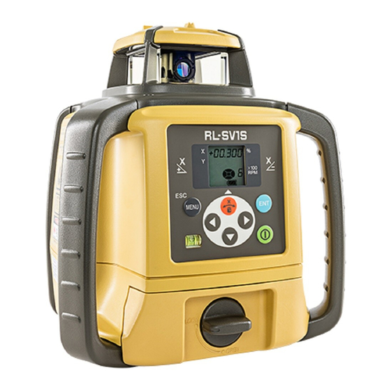
4. NOMENCLATURE 4.1 RL-SV1S/RC-50 RL-SV1S Nomenclature Sight Rotary head X axis Beam aperture Control panel selection key/ Alignment key/ Display Up key Menu key/ Enter key Escape key Handle Power switch Level vial For Vertical Rotation Battery holder Arrow keys... -
Page 21: Nomenclature
Up key Strap hole • Turn ON the power of the RL-SV1S before using the RC-50. Pressing one of the keys (or inserting the battery) will display the channel search (CH SErCH) and begin transmission with the RL-SV1S. • When the channel is not aligned with the RL-SV1S or when the RL-SV1S power is not turned ON, the display will show "Transmission error with remote control"... -
Page 22: Rl-Sv1S/Rc-50 Key Operation
4. NOMENCLATURE • The RC-50 is a remote controller specifically designed for the RL-SV1S and cannot be used with other models. • The remote controller RC-60 cannot be used with the RL-SV1S. RL-SV1S/RC-50 Key Operation Nomenclature Function Enter key End Operation of Data Input and Sends data to the instrument. -
Page 23: Rl-Sv1S/Rc-50 Display
4. NOMENCLATURE RL-SV1S/RC-50 Display Sample display X axis grade Mask Mode display (Flashes one digit at a time during auto leveling) Rotation speed Y axis 6: 600 rpm 3: 300 rpm Manual Mode display Battery remaining Transmission and reception display... -
Page 24: Level Sensor Ls-80L
Beam receiving window Buzzer sound switch Turn the beam receiving window side Volume of the sensor buzzer can be towards RL-SV1S to detect the laser alternately switched to beam. LOW/LOUD/OFF by pressing the switch. Buzzer speaker Auto-cut off function The power will be turned off automatically if no laser beam is detected for approximately 30 minutes. -
Page 25: Ls-80L Display
Battery is sufficient. • The warning displays *1 and *2 are the functions that the LS-80L detects alarm signal from the RL-SV1S. The power is low, but laser The LS-80L can be canceled the alarm detection from the is still usable. -
Page 26: Ls-80L Detective Range
4. NOMENCLATURE LS-80L Detective Range... -
Page 27: Preparation And Functions
5. PREPARATION AND FUNCTIONS 5.1 Power Source Connect the battery according to the battery type purchased. RL-SV1S (Dry battery type) • How to install dry cell batteries Remove the DB-74 battery holder by turning battery holder knob to "OPEN" side. - Page 28 5. PREPARATION AND FUNCTIONS • How to remove dry cell batteries Remove the DB-74 battery holder by turning battery holder knob to "OPEN" side. Remove the dry cell batteries from the DB-74 battery holder. *1Replace all 4 batteries with new ones at the same time. Do not mix used and new batteries, and do not mix different types of batteries together.
-
Page 29: Rl-Sv1S (Rechargeable Battery Type)
5. PREPARATION AND FUNCTIONS RL-SV1S (Rechargeable battery type) • How to install the battery pack BT-74Q Insert the battery pack BT-74Q into the DB-74C battery holder in the direction shown in the diagram on the right. Install the battery holder. Tighten the battery DB-74C cover knob to "LOCK"... - Page 30 5. PREPARATION AND FUNCTIONS • For Charging • Be sure to charge the battery fully before using it for the first time or after not using it for long periods. Select a power plug which will be fit to the shape of the power outlet to be used.
- Page 31 5. PREPARATION AND FUNCTIONS Complete charging by unplugging the plug from the DB-74C battery holder or battery pack BT-74Q after approximately 13 hours. Unplug the AD-15 power plug from the power outlet. • RUN charge As illustrated at the right, while charging is in process with the power supply unit installed to the instrument, you can use the instrument.
- Page 32 5. PREPARATION AND FUNCTIONS RC-50 • How to install dry cell batteries Open the battery cover. Remove the old batteries and replace with new 2xAA size dry cell batteries (alkaline) making sure each is placed in the proper direction as indicated. Shut the battery cover until click sound can be heard.
-
Page 33: How To Set Remote Controller Communication Channel
5. PREPARATION AND FUNCTIONS 5.2 How to set remote controller communication channel The same channel (1 to 9) must be set on the RL-SV1S and the RC-50 remote controller. RL-SV1S Setting channel (p. 48) RC-50 The setting method is the same as for the RL-SV1S. Use the RC-50 control panel for setting. -
Page 34: Basic Operation
The RL-SV1S automatically levels within the range of ±5° as shown below. It is also possible to set grade for the RL-SV1S in the X axis direction. 7.1 Setting Grade(p. 30) on how to set grade. ±5°... - Page 35 6. BASIC OPERATION Press power switch on the LS-80L (ON). Select the precision mode by pressing the On-Grade precision switch. 4.2 Level Sensor LS-80L(p. 16) Locate the on-grade position “---” by moving the LS-80L up and down. Mark the position of On-Grade index. (Top of the LS-80L is 40mm [1 9/16”] from index for offset marking.)
-
Page 36: Example Operational
1 3 2 1 3 1 Vertical Rotation Install the RL-SV1S on to the tripod and set so that the bubble is at the center of the vertical rotation circular level vial. Press power switch When auto leveling is complete, the laser beam will emit vertically. -
Page 37: Height Alert Function
6. BASIC OPERATION 6.2 Height Alert Function When the instrument system detects a shock, this Shock is given to the instrument. function informs the operator of it. • When the instrument’s installation status (height) is Height Alert Display sharply changed by the contact of the operator or the like, this function stops auto leveling to keep the operation accuracy and informs the operator of the situation. -
Page 38: Applied Operation And Setting Of Various Functions
7. APPLIED OPERATION AND SETTING OF VARIOUS FUNCTIONS It is possible to set grade for the laser beam and various functions from the menu screen. 7.1 Setting Grade There are two methods to set grade on the laser beam: 1) direct entry of the grade value for the X axis, and 2) matching to set grade on laser beam according to the slope of the ground on site. - Page 39 "Exceeding leveling range" will be displayed.12. ERROR DISPLAY(p. 66) • If you set grade by placing the RL-SV1S in a place where temperature suddenly changes, let the instrument stand for about 10 minutes to allow it to adjust to the temperature prior to actual use.
-
Page 40: How To Set Grade
7. APPLIED OPERATION AND SETTING OF VARIOUS FUNCTIONS How to set grade Resetting the grade value When pressing the key, the sign of X axis will When pressing the key, the start flashing. sign of X axis will start flashing. Press the keys and select the sign (plus or Press both the... - Page 41 7. APPLIED OPERATION AND SETTING OF VARIOUS FUNCTIONS Press the key to confirm the value. • To set with the RC-50, check the transmission and reception display.
-
Page 42: Example Of How To Set Up
7. APPLIED OPERATION AND SETTING OF VARIOUS FUNCTIONS Example of how to set up When setting grade, it is necessary to accurately set the RL-SV1S to the direction of grade setting. Below is an example of how to set grade to the accurate grade setting direction. (To work at... - Page 43 LS-80L with the laser beam and fix. Set the RL-SV1S at X+3.000% grade. Align the RL-SV1S direction on top of the tripod so as to have the laser beam in the on- grade position of the LS-80L in step ...
-
Page 44: Matching Mode (Manual Slope)
Set up the LS-80L in step on the grade surface. Using the sight, roughly align and set the position of the RL-SV1S on top of the tripod to the direction of the LS-80L. Press the key. - Page 45 7. APPLIED OPERATION AND SETTING OF VARIOUS FUNCTIONS Confirm that auto leveling is Grading direction of the laser beam during arrow key operation complete and that the laser beam is emitting. Display* Grading direction of the laser beam Press the arrow key ( align with grade on the X- side) once in the desired direction to align grades, and the laser beam...
- Page 46 , or key is long-pushed in step , the laser beam grading may stop. If this interferes with the operation, change the communication channel for the RL-SV1S and RC-50 and try again. 5.2 How to set remote controller communication channel(p. 25)
- Page 47 7. APPLIED OPERATION AND SETTING OF VARIOUS FUNCTIONS [Display during the Matching Mode] is flashing: in the Matching Mode. It is possible to adjust the grade of the laser beam with arrow keys. When a certain amount of time has passed after the arrow key operation, the light that was flashing will remain lit.
-
Page 48: Line Control (Manual Vertical Beam Alignment)
Move and set the RL-SV1S to align reference point A and the laser beam. • Make sure that the RL-SV1S is set so that the bubble is at the center of the vertical rotation circular level vial on the control panel. - Page 49 7. APPLIED OPERATION AND SETTING OF VARIOUS FUNCTIONS Press the key to enter the Line Control Mode. is flashing: in the Line Control Mode. It is possible to adjust the laser beam with key. When a certain amount of time has passed after the key operation, the light that was flashing will remain lit.
- Page 50 7. APPLIED OPERATION AND SETTING OF VARIOUS FUNCTIONS Direction of laser beam movement when operating Display Direction of laser beam movement * Display during arrow key operation (p. 38) When readjusting with line control, return to step and follow directions thereafter. In such a case, however, skip steps ...
- Page 51 7, the laser beam grading may stop. If this interferes with the operation, change the transmission channels for the RL-SV1S and the RC-50 and try again. 5.2 How to set remote controller communication channel(p. 25)
-
Page 52: Setting Of Various Functions
7. APPLIED OPERATION AND SETTING OF VARIOUS FUNCTIONS 7.3 Setting of Various Functions Selecting MENU After pressing the key, pressing the key will change the menu items and setting can be performed for the functions listed below. Matching Mode Masking setting Safety lock ON/OFF setting Manual Mode ON/... -
Page 53: Masking (Laser Beam Shutter) Setting
(Laser beams are emitted to all directions.) Displays the masking direction The status in which the Y+ direction is masked. (Laser beam is shut off in the Y+ RL-SV1S upper Arrow keys and masking direction.) setting directions surface diagram and masking directions... -
Page 54: How To Change The Rotary Head Speed
7. APPLIED OPERATION AND SETTING OF VARIOUS FUNCTIONS When desired masking is displayed, press the key to finish. How to change the rotary head speed The rotary head speed can be set to 600 or 300 R.P.M. Press the key to display the menu screen. -
Page 55: Switching Auto Leveling / Manual Mode
7. APPLIED OPERATION AND SETTING OF VARIOUS FUNCTIONS Switching Auto leveling / Manual Mode Auto leveling function can be canceled and switched to Manual Mode. Auto leveling OFF (LEVEL OFF): After auto leveling is complete, the auto leveling function will stop. -
Page 56: Setting Channel
Setting is complete. After setting, be sure to shift to other modes by pressing the key. The RL-SV1S and RC-50 cannot communicate with each other in the communication channel setting mode. -
Page 57: Sleep Mode
• Press one of the keys on RC-50. • Turn OFF the power using the power key for the RL-SV1S, and turn the power back on. After reverting from the Sleep Mode, the former status is kept in the selected mode except... -
Page 58: Height Alert On/Off
7. APPLIED OPERATION AND SETTING OF VARIOUS FUNCTIONS Height Alert ON/OFF 6.2 Height Alert Function(p. 29) Press the key. Press the key and select Safety Lock ON/OFF (Hl.ALr), and press the key. Press the key and select ON or OFF, and press the key. -
Page 59: Check And Adjusting
Handle level with the X1 facing the wall. Control Panel While pressing the key, turn ON the power. (Only the RL-SV1S is operable). LS-80L [CaLIb] will flash on the X axis screen. *1) X- laser beam X- laser position Staff or Wall Press the key. - Page 60 Detect the center of the laser beam on the wall with the LS-80L and mark it. (X1) Press the key. Loosen the centering screw and rotate the RL-SV1S 180°, and tighten the screw to secure. The RL-SV1S X+ surface will face the wall. When rotating the RL-SV1S, ensure that the instrument height is not misaligned.
- Page 61 Press the key. axis check and adjusting mode. the Y axis direction, press the key. • A difference between X1 and X2 is more than 40 mm (±90"), it is outside of the adjustment range. Contact your dealer or Topcon.
- Page 62 Adjustment for X axis is complete. Turn OFF the power. Exceeding the range of adjustment. 12. ERROR DISPLAY(p. 66) The RL-SV1S is calculating the correction value. Do not touch the RL-SV1S until [End] is displayed. (If you touch it, you will need to readjust.)
-
Page 63: Horizontal Rotation Cone Error
Locate and mark the position of the RL-SV1S beam on both walls using the LS-80L. Turn off the RL-SV1S and move the RL-SV1S closer to wall A (1 m to 2 m /3 ft to 6 ft). Do not change the axis orientation of the RL-SV1S. Turn the RL-SV1S on. -
Page 64: Grade Setting Error
• If the difference between [wall A]-side and [wall B]-side exceeds ±5 mm (±7/32 of an inch), contact your dealer or Topcon. Grade Setting Error Perform the following check only after completing “Horizontal Rotation Grade Error” and “Horizontal Rotation Cone Error”. - Page 65 8. CHECK AND ADJUSTING Turn on power for the RL-SV1S and verify the staff height of Nail 1 and Nail 2 at grade setting of 0% with LS-80L and record. At this time the staff height for Nail 1 and Nail 2 should recorded as h1 and h2 (mm). Check the LS-80L is set at high precision.
-
Page 66: Vertical Calibration
Mark the standard line on the floor perpendicular to Approx.10m the direction of the beam where Point A crosses. Set up the RL-SV1S for vertical rotation at the position shown in the diagram and turn ON the power. Standard line... -
Page 67: Vertical Calibration And Adjustment
Press the key. Move the RL-SV1S in the direction of the arrow to align the standard line and laser beam. Press either the key or the key to align the laser beam with the LS-80L indicator... - Page 68 If the screen below is displayed, the adjustment is complete. Turn OFF the power. The RL-SV1S is calculating the correction value. Do not touch the RL-SV1S until [End] is displayed. (If you touch it, you will need to readjust.) ...
-
Page 69: Storage Precautions
9. STORAGE PRECAUTIONS Always clean the instrument after use. • If the instrument got wet with rain, wipe it well before storing in the storage case. • Wipe away stain or dirt with soft cloth after dusting. • Clean storage case using cloth moistened with neutral detergent or water. Do not use ether, benzene, thinner or other solvents. -
Page 70: How To Store
LS-80L, LS-B10/B10W : After using the instrument, store it as shown below. (LS-70 cannot be stored.) LS-100D : Refer to the instruction manual of LS-100D. RC-50 LS-80L (LS-80A/80B/90) Level Sensor Holder Model-6 RL-SV1S LS-B10/B10W AD-15 D-size dry cell batteries AA-size dry cell batteries... -
Page 71: Specifications
11. SPECIFICATIONS RL-SV1S Light source Laser diode (Visible, 635nm) Laser output 2.4mW Safety standard for laser beam : CDRH (FDA) Class IIIa, IEC Class 3R Automatic correction range Horizontal ±5° Vertical ±5° Grade setting range X:±15% Accuracy Horizontal ±10" Vertical ±10"... - Page 72 –20 °C to +50 °C (–4 °F to +122 °F) Storable temperature range –30 °C to +60 °C (–22 °F to +140 °F) LS warning display RL-SV1S height alert warning (Warning is displayed on the indicator of LS-80L.) RL-SV1S battery warning (Warning is displayed on the indicator of LS-80L.) Dimensions 177 (L) ×...
- Page 73 11. SPECIFICATIONS LS-80L (Back side display area) Beam detection window 50 mm (2.0 in) Beam detection precision High precision ±1 mm (±0.04 in) Normal precision ±2 mm (±0.08 in) Beam detection indication Liquid crystal (both sides) and buzzer Power source 2×AA size dry cell batteries Operating time Approx.
-
Page 74: Error Display
Description/Countermeasure The Height Alert Function is working. 6.2 Height Alert Function(p. 29) RL-SV1S setting exceeds the leveling range. Reset tilting to the direction to raise the X+ side. Reset tilting to the direction to raise the X- side. Alternate flashing Reset tilting to the direction to raise the Y+ side. - Page 75 Turn the power for the instrument off, and then turn it back on in stable locations. Internal memory error for the RL-SV1S. E-99 Turn the power for the instrument off, and then turn it back on. • If errors still persist after attempting to clear them, contact Topcon or your dealer.
- Page 76 After recovering from the error, be sure to check the setting for each function of the RL-SV1S. Exceeding the adjustment range. Turn the power of the RL-SV1S OFF, turn ON the power back again and readjust. This is an error with the RL-SV1S. Check the RL-SV1S display.
-
Page 77: Regulations
13. REGULATIONS Region/ Directives/ Labels/Declarations Country Regulations FCC Compliance WARNING: Changes or modifications to this unit not expressly approved by the party responsible for compliance could void the user's authority to operate the equipment. NOTE: This equipment has been tested and found to comply with limits for a Class B digital device, pursuant to Part 15 of the FCC Rules. - Page 78 13. REGULATIONS Means of conformity This device complies with part 15 of the FCC Rules, Operation is subject to the following two conditions: (1) This device may not cause harmful interference, and (2) this device must accept any interference received, including interference that may cause undesired operation.
- Page 79 13. REGULATIONS California, Recycling and NY, Batteries U.S.A.
- Page 80 13. REGULATIONS Region/ Directives/ Labels/Declarations Country Regulations This class B digital apparatus meets all requirements of Canadian interference- Causing Equipment Regulations. Cet appareil numérique de la class B respecte toutes les exigences du Réglement sur le matérique brouilleur du Canada. This Class B digital apparatus complies with Canadian ICES-003 Cet appareil numerique de la Class B est conforme a la norme NMB-003 du Canada.
- Page 81 Under such conditions, please test the instrument performance before use. Hereby, TOPCON CORPORATION declares that the radio equipment type of this product is in compliance with Directive 2014/53/EU. EU declaration of conformity is available depending on your request.
- Page 82 13. REGULATIONS Region/ Directives/ Labels/Declarations Country Regulations WEEE Directive This symbol is applicable to EU members states only. Following information is only for EU-member states: WEEE The use of the symbol indicates that this product may not be treated as Directive household waste.
- Page 84 Please see the following website for contact addresses. GLOBAL GATEWAY http://global.topcon.com/ ©2017 TOPCON CORPORATION ALL RIGHTS RESERVED...
Need help?
Do you have a question about the RL-SV1S and is the answer not in the manual?
Questions and answers