Juniper EX2200 Hardware Manual
Ex series
Hide thumbs
Also See for EX2200:
- Hardware manual (354 pages) ,
- User manual (238 pages) ,
- Complete hardware manual (176 pages)

Related Manuals for Juniper EX2200


Summary of Contents for Juniper EX2200
- Page 1 EX2200 and EX2200-C Switches Hardware Guide Modified: 2017-07-05 Copyright © 2017, Juniper Networks, Inc.
- Page 2 END USER LICENSE AGREEMENT The Juniper Networks product that is the subject of this technical documentation consists of (or is intended for use with) Juniper Networks software. Use of such software is subject to the terms and conditions of the End User License Agreement (“EULA”) posted at http://www.juniper.net/support/eula.html.
-
Page 3: Table Of Contents
EX2200 Switches Hardware Overview ........3... - Page 4 Power Specifications and Requirements ......61 Power Specifications for EX2200 Switches ......61 AC Power Cord Specifications for EX2200 Switches .
- Page 5 Mounting an EX2200 Switch on a Wall ....... . .
- Page 6 Rack-Mounting and Cabinet-Mounting Warnings ......192 Wall-Mounting Warnings for EX2200 Switches ......196 Grounded Equipment Warning .
- Page 7 Nonregulatory Environmental Standards ......229 Compliance Statements for Acoustic Noise for EX Series Switches ..230 Copyright © 2017, Juniper Networks, Inc.
- Page 8 EX2200 and EX2200-C Switches Hardware Guide viii Copyright © 2017, Juniper Networks, Inc.
- Page 9 EX2200-C Switch Models ........
- Page 10 Inlet on an EX2200 Switch ........
- Page 11 Components ........... . . 157 Figure 60: Location of the Serial Number ID Label on EX2200 Switches ..159...
- Page 12 EX2200 and EX2200-C Switches Hardware Guide Copyright © 2017, Juniper Networks, Inc.
- Page 13 Uplink Ports in EX2200 Switches ........
- Page 14 Table 47: Parts List for EX2200 Switches ....... . 86...
-
Page 15: About The Documentation
® To obtain the most current version of all Juniper Networks technical documentation, see the product documentation page on the Juniper Networks website at http://www.juniper.net/techpubs/ If the information in the latest release notes differs from the information in the documentation, follow the product Release Notes. -
Page 16: Table 1: Notice Icons
EX2200 and EX2200-C Switches Hardware Guide Table 1: Notice Icons Icon Meaning Description Informational note Indicates important features or instructions. Caution Indicates a situation that might result in loss of data or hardware damage. Warning Alerts you to the risk of personal injury or death. -
Page 17: Documentation Feedback
We encourage you to provide feedback, comments, and suggestions so that we can improve the documentation. You can provide feedback by using either of the following methods: Online feedback rating system—On any page of the Juniper Networks TechLibrary site , simply click the stars to rate the content, http://www.juniper.net/techpubs/index.html and use the pop-up form to provide us with information about your experience. -
Page 18: Requesting Technical Support
7 days a week, 365 days a year. Self-Help Online Tools and Resources For quick and easy problem resolution, Juniper Networks has designed an online self-service portal called the Customer Support Center (CSC) that provides you with the following features: Find CSC offerings: http://www.juniper.net/customers/support/... - Page 19 About the Documentation For international or direct-dial options in countries without toll-free numbers, see http://www.juniper.net/support/requesting-support.html Copyright © 2017, Juniper Networks, Inc.
- Page 20 EX2200 and EX2200-C Switches Hardware Guide Copyright © 2017, Juniper Networks, Inc.
-
Page 21: Overview
PART 1 Overview System Overview on page 3 Chassis Components and Descriptions on page 13 Cooling System and Airflow on page 19 Power Supplies on page 23 Viewing System Information on page 25 Copyright © 2017, Juniper Networks, Inc. - Page 22 EX2200 and EX2200-C Switches Hardware Guide Copyright © 2017, Juniper Networks, Inc.
-
Page 23: System Overview
Rear Panel of an EX2200 Switch on page 8 EX2200 Switches First View EX2200 switches are available in models with 12 , 24, or 48 built-in network ports. The compact, fanless model, EX2200-C switches have 12 network ports. Copyright © 2017, Juniper Networks, Inc. -
Page 24: Uplink Ports
Each EX2200 switch except the EX2200-C switch model has an RJ-45 console port that accepts a cable with RJ-45 connector. The EX2200-C switch has two console ports: an RJ-45 port and a Mini-USB Type-B port. The RJ-45 console port accepts a cable with an RJ-45 connector and the Mini-USB Type-B console port accepts a Mini-B plug (5-pin) connector to connect to the console management device. -
Page 25: Cable Guard
Surface” on page Security Slots Each EX2200-C switch model has security slots on the left and right panels of the chassis. Use the security slots to lock and secure the chassis in the installation site with a standard cable lock . See “Mounting an EX2200 Switch on a Desk or Other Level Surface”... -
Page 26: Front Panel Of An Ex2200 Switch
EX2200 and EX2200-C Switches Hardware Guide Front Panel of an EX2200 Switch The front panel of an EX2200 switch except the EX2200-C switch models consists of the following components: Network ports—depending on the switch model, either of: 24 or 48 10/100/1000BASE-T Gigabit Ethernet ports, with Power over Ethernet... -
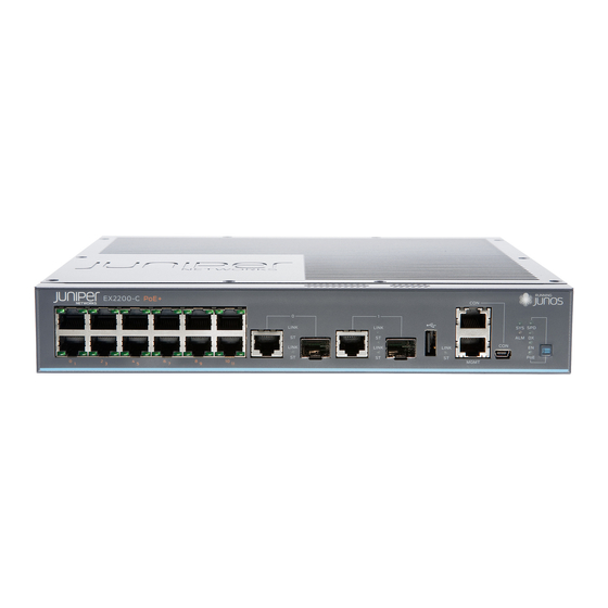
Page 27: Figure 3: Front Panel Of An Ex2200-C Switch With 12 Gigabit Ethernet Ports
Chapter 1: System Overview The front panel of an EX2200-C switch consists of the following components: Network ports—depending on the switch model, either of: 12 10/100/1000BASE-T Ethernet ports, (PoE+) in EX2200-C-12P 12 10/100/1000BASE-T Ethernet ports, (non-PoE) in EX2200-C-12T 2 built-in dual-purpose uplink ports, each of which includes one 10/100/1000 RJ-45... -
Page 28: Rear Panel Of An Ex2200 Switch
EX2200 and EX2200-C Switches Hardware Guide Rear Panel of an EX2200 Switch The rear panel of the EX2200 switch except the EX2200-C switch models consists of the following components: Management Ethernet port USB port Console port Protective earthing terminal Redundant power system (RPS) port... -
Page 29: Ex2200 Switch Models
Site Preparation Checklist for EX2200 Switches on page 47 EX2200 Switch Models The EX2200 switch is available with 12, 24, or 48 built-in network ports with full Power over Ethernet (PoE) capability (all 12, 24, or 48 built-in network ports support PoE) or no PoE capability. -
Page 30: Ex2200 Switch Hardware And Cli Terminology Mapping
EX2200 and EX2200-C Switches Hardware Guide EX2200 Switch Hardware and CLI Terminology Mapping This topic describes the hardware terms used in EX2200 switch documentation and the corresponding terms used in the Junos OS command line interface (CLI). See Table 4 on page... -
Page 31: Switches
Chapter 1: System Overview Table 4: CLI Equivalents of Terms Used in Documentation for EX2200 Switches (continued) Hardware Item (as Description (as Value (as displayed Item in Additional displayed in the CLI) displayed in the CLI) in the CLI) Documentation... - Page 32 EX2200 and EX2200-C Switches Hardware Guide Copyright © 2017, Juniper Networks, Inc.
-
Page 33: Chassis Components And Descriptions
Management Port LEDs in EX2200 Switches on page 15 Network Port and Uplink Port LEDs in EX2200 Switches on page 16 Chassis Physical Specifications for EX2200 Switches The EX2200 switch chassis is a rigid sheet-metal structure that houses the hardware components. Table 5 on page 13 summarizes the physical specifications of the EX2200 switch chassis. -
Page 34: Chassis Status Leds In Ex2200 Switches
EX2200 and EX2200-C Switches Hardware Guide Chassis Status LEDs in EX2200 Switches The front panel of an EX2200 switch has two chassis status LEDs labeled SYS and ALM on the far right side of the panel. See Figure 7 on page 14... -
Page 35: Management Port Leds In Ex2200 Switches
Understanding Alarm Types and Severity Levels on EX Series Switches on page 165 Management Port LEDs in EX2200 Switches The management port on an EX2200 switch has two LEDs that indicate link/activity and port status. The EX2200 switches except the EX2200-C switch models have the management port on the rear panel and the EX2200-C switch has the management port on the front panel. -
Page 36: Network Port And Uplink Port Leds In Ex2200 Switches
Documentation Network Port and Uplink Port LEDs in EX2200 Switches Each network port and uplink port on the front panel of an EX2200 switch has two LEDs that indicate link/activity and port status. Each dual-purpose uplink port in an EX2200-C switch has two pairs of LEDs that indicate the link/activity status, one pair for each of the two ports that constitute the dual-purpose uplink port. -
Page 37: Figure 13: Port Status Mode Leds Of The Dual-Purpose Uplink Ports Of An
Figure 13: Port Status Mode LEDs of the Dual-Purpose Uplink Ports of an EX2200-C Switch Table 9 on page 17 describes the Link/Activity LED. Table 9: Link/Activity LED on the Network Ports and Uplink Ports in EX2200 Switches Color State and Description Link/Activity Green Blinking—The port and the link are active, and there is link activity. - Page 38 A device that draws power from the port is connected to the port, but the device is not drawing any power from the port. Off—PoE is not available on the port. NOTE: PoE Status LED is available on the following EX2200 switch models: EX2200-C-12P EX2200-24P EX2200-48P PoE is not available on uplink ports;...
-
Page 39: Cooling System And Airflow
In the PoE models of these switches, there is an additional fan in the power supply. In the EX2200-C switch the cooling is done by the vents on top and sides of the chassis in non-PoE models and by heatsinks in PoE+ models. Do not block the vents on the chassis. -
Page 40: Airflow Direction In Poe Models Of Ex2200 Switches, Except For The Ex2200-C Models
Figure 14: Airflow Through Non-PoE Models of EX2200 Switches Except the EX2200-C Switch Model Airflow Direction in PoE Models of EX2200 switches, Except for the EX2200-C Models Figure 15 on page 21 shows the airflow in PoE models of EX2200 switches, except EX2200-C models. -
Page 41: Figure 15: Airflow Through Poe Models Of Ex2200 Switches Except The Ex2200-C Switch Models
Chapter 3: Cooling System and Airflow Figure 15: Airflow Through PoE Models of EX2200 Switches Except the EX2200-C Switch Models Under normal operating conditions, the fans operate at a moderate speed to reduce noise. Temperature sensors in the chassis monitor the temperature within the chassis. - Page 42 EX2200 and EX2200-C Switches Hardware Guide Copyright © 2017, Juniper Networks, Inc.
-
Page 43: Power Supplies
Power Supply in EX2200 Switches The power supply in EX2200 switches is built in along the rear panel of the chassis, with an AC power cord inlet or DC power terminals on the rear panel to connect power to the switch. - Page 44 EX2200 and EX2200-C Switches Hardware Guide Connecting AC Power to an EX2200 Switch on page 121 Connecting DC Power to an EX2200 Switch on page 123 Connecting Earth Ground to an EX Series Switch on page 115 Copyright © 2017, Juniper Networks, Inc.
-
Page 45: Viewing System Information
NOTE: This topic applies only to the J-Web Application package. When you log in to the J-Web user interface, the dashboard for the Juniper Networks EX Series Ethernet Switches appears. Use the dashboard to view system information. The Update Available window appears if there is a latest update of the J-Web Application package available on the Juniper Networks server. -
Page 46: Graphical Chassis Viewer
EX2200 and EX2200-C Switches Hardware Guide File System Usage on page 32 Chassis Viewer on page 32 Graphical Chassis Viewer The Dashboard panel displays a graphical view of the chassis of a switch. In a Virtual Chassis, it displays a graphical view of each member switch. -
Page 47: System Information Panel
NOTE: In a Virtual Chassis setup for an EX6210, EX8208, or EX8216 switch, the Device model field displays details of the master Routing Engine. To view details of a member, select it. Copyright © 2017, Juniper Networks, Inc. - Page 48 Virtual Chassis, the value displayed in Inventory details field is always 1 FPC. FPC is a legacy term for a slot in a large Juniper Networks chassis; which simply refers to the standalone switch. For EX2200 and EX2200-C switches configured as a Virtual Chassis, the value displayed in the Inventory details field is 1–4 FPC, with the number corresponding to the number of...
-
Page 49: Health Status Panel
EX2200-C switch. Temp Temp field is dynamically available for an EX2200 Virtual Chassis switch based on the model of the member clicked. NOTE: In EX4300 Virtual Chassis, the temperature of the master Routing Engine is displayed by default. - Page 50 NOTE: field is unavailable for a standalone EX2200-C switch. Fan status field is dynamically available for an EX2200 Virtual Chassis switch based on the Fan status model of the member clicked. In EX4600 Virtual Chassis, mouse over the fan icon to display the fan status of all the switches.
-
Page 51: Capacity Utilization Panel
Alarms Panel Displays information about the last five alarms raised in the system. For example, if there are 5 major alarms, then details of all 5 major alarms are displayed. If there are 4 major Copyright © 2017, Juniper Networks, Inc. -
Page 52: File System Usage
Rear View button is disabled if the switch is not selected. Table 17 on page 32—Describes the chassis viewer for EX2200 switches. Table 18 on page 33—Describes the chassis viewer for EX2200-C switches. Table 19 on page 33—Describes the chassis viewer for EX3200, EX3300, and EX4200 switches. -
Page 53: Table 18: Chassis Viewer For Ex2200-C Switches
USB port Indicates the USB port for the switch. NOTE: We recommend that you use USB flash drives purchased from Juniper Networks for your EX Series switch. Fan tray Mouse over the fan tray icon to display name, status, and description information. - Page 54 USB port Indicates the USB port for the switch. NOTE: We recommend that you use USB flash drives purchased from Juniper Networks for your EX Series switch. Fan tray Mouse over the fan tray icon to display name, status, and description information.
-
Page 55: Table 20: Chassis Viewer For Ex4300 Switches
Description USB port Indicates the USB port for the switch. NOTE: We recommend that you use USB flash drives purchased from Juniper Networks for your EX Series switch. Management ( ) port The management port is used to connect the switch to a management device for out-of-band management. -
Page 56: Table 21: Chassis Viewer For Ex4500 Switches
USB port Indicates the USB port for the switch. NOTE: We recommend that you use USB flash drives purchased from Juniper Networks for your EX Series switch. Fan tray Mouse over the fan tray icons to display name, status, and description information. -
Page 57: Table 22: Chassis Viewer For Ex4550 Switches
Use this port for initial switch configuration. USB port Indicates the USB port for the switch. NOTE: We recommend that you use USB flash drives purchased from Juniper Networks for your EX Series switch. Rear View of the EX4500 Switch Fan tray Mouse over the fan tray icon to display status of the fans and airflow direction information. - Page 58 (uplink or Virtual Chassis). USB port Indicates the USB port for the switch. NOTE: We recommend that you use USB flash drives purchased from Juniper Networks for your EX Series switch. Rear View of the EX4550 Switch Fan tray Mouse over the fan tray icon to display the status of the fans and airflow direction information.
-
Page 59: Table 23: Chassis Viewer For Ex4600 Switches
USB port Indicates the USB port for the switch. NOTE: We recommend that you use USB flash drives purchased from Juniper Networks for your EX Series switch. Fan tray Mouse over the fan tray icons to display name, status, and description information. -
Page 60: Table 25: Chassis Viewer For Ex8208 Switches
You can view status for the following ports on the SRE module: USB port—Indicates the USB port for the switch. NOTE: We recommend that you use USB flash drives purchased from Juniper Networks for your EX Series switch. Management ( ) port—The management port is used to connect the switch to a management... - Page 61 You can view status for the following ports on the SRE module: USB port—Indicates the USB port for the switch. NOTE: We recommend that you use USB flash drives purchased from Juniper Networks for your EX Series switch. Auxiliary port—This port is unavailable.
-
Page 62: Table 26: Chassis Viewer For Ex8216 Switches
You can view status for the following ports on the RE module: USB port—Indicates the USB port for the switch. NOTE: We recommend that you use USB flash drives purchased from Juniper Networks for your EX Series switch. Auxiliary port—This port is unavailable. - Page 63 USB port Indicates the USB port for the switch. NOTE: We recommend that you use USB flash drives purchased from Juniper Networks for your EX Series switch. PIC1 slot You can install a Virtual Chassis module in the PIC1 slot. Mouse over the Virtual Chassis ports to display the port status details.
- Page 64 J-Web is supported on EX4600 switches only in J-Web Application package Release 14.1X53-A2. Related J-Web User Interface for EX Series Switches Overview Documentation EX2200 Switches Hardware Overview on page 3 EX2300 Switches Hardware Overview EX3200 Switches Hardware Overview EX3300 Switches Hardware Overview EX4200 Switches Hardware Overview...
-
Page 65: Part 2 Site Planning, Preparation, And Specifications
PART 2 Site Planning, Preparation, and Specifications Preparation Overview on page 47 Power Specifications and Requirements on page 61 Transceiver and Cable Specifications on page 67 Pinout Specifications on page 73 Copyright © 2017, Juniper Networks, Inc. - Page 66 EX2200 and EX2200-C Switches Hardware Guide Copyright © 2017, Juniper Networks, Inc.
-
Page 67: Preparation Overview
Site Electrical Wiring Guidelines on page 53 Chassis Physical Specifications for EX2200 Switches on page 54 Requirements for Mounting an EX2200 Switch on a Desktop or Wall on page 55 Rack Requirements on page 55 Cabinet Requirements on page 56... -
Page 68: Environmental Requirements And Specifications For Ex Series Switches
General Safety Guidelines and Warnings on page 181 Documentation General Site Guidelines on page 53 Installing and Connecting an EX2200 Switch on page 89 Mounting an EX2200 Switch on page 90 Environmental Requirements and Specifications for EX Series Switches The switch must be installed in a rack or cabinet housed in a dry, clean, well-ventilated, and temperature-controlled environment. -
Page 69: Table 29: Ex Series Switch Environmental Tolerances
Complies with Zone 4 degradation up to the relative humidity range temperature range 32° F (0° C) earthquake 10,000 feet 10% through 85% through 113° F (45° C) requirements as per (3048 meters) (noncondensing) GR-63, Issue 4. Copyright © 2017, Juniper Networks, Inc. - Page 70 EX2200 and EX2200-C Switches Hardware Guide Table 29: EX Series Switch Environmental Tolerances (continued) Environment Tolerance Switch or device Altitude Relative Humidity Temperature Seismic EX3300 No performance Normal operation ensured in Normal operation ensured in the Complies with Zone 4...
- Page 71 10,000 feet 5% through 90% (0° C) through 104° F (40° C) requirements as per (3048 meters) (noncondensing) GR-63. Nonoperating storage temperature in shipping container: –40° F (–40° C) to 158° F (70° C) Copyright © 2017, Juniper Networks, Inc.
- Page 72 Articles 110–16, 110–17, and 110–18 of the National Electrical Code, ANSI/NFPA 70. Related Clearance Requirements for Airflow and Hardware Maintenance for EX2200 Switches Documentation on page 57 Clearance Requirements for Airflow and Hardware Maintenance for EX2300 Switches...
-
Page 73: General Site Guidelines
Improperly installed wires cause radio frequency interference (RFI). Damage from lightning strikes occurs when wires exceed recommended distances or pass between buildings. Electromagnetic pulses (EMPs) caused by lightning damage unshielded conductors and electronic devices. Copyright © 2017, Juniper Networks, Inc. -
Page 74: Chassis Physical Specifications For Ex2200 Switches
General Electrical Safety Guidelines and Warnings on page 209 Prevention of Electrostatic Discharge Damage on page 211 Chassis Physical Specifications for EX2200 Switches The EX2200 switch chassis is a rigid sheet-metal structure that houses the hardware components. Table 5 on page 13 summarizes the physical specifications of the EX2200 switch chassis. -
Page 75: Requirements For Mounting An Ex2200 Switch On A Desktop Or Wall
Insert the screws into wall studs wherever possible to provide added support for the chassis. Use the wall-mount kit from Juniper Networks to mount the switch on a wall. The wall-mount kit is not part of the standard package and must be ordered separately. -
Page 76: Cabinet Requirements
EX2200 and EX2200-C Switches Hardware Guide Table 32: Rack Requirements and Specifications (continued) Rack Requirement Guidelines Mounting bracket hole spacing The holes in the mounting brackets are spaced at 1 U (1.75 in. or 4.45 cm), so that the device can be mounted in any rack that provides holes spaced at that distance. -
Page 77: Switches
Rack-Mounting and Cabinet-Mounting Warnings on page 192 Documentation Clearance Requirements for Airflow and Hardware Maintenance for EX2200 Switches When planning the site for installing an EX2200 switch, you must allow sufficient clearance around the installed switch. Figure 16 on page 57 shows the clearance requirement for EX2200 switches except the EX2200-C switch models. -
Page 78: Figure 17: Clearance Requirements For Airflow And Hardware Maintenance For
For the cooling system to function properly, the airflow around the chassis must be unrestricted. Figure 18 on page 58 shows the airflow in PoE models of EX2200 switches, except for EX2200-C models. Figure 19 on page 59 shows the airflow non-PoE models of EX2200 switches, except for EX2200-C models. -
Page 79: Figure 19: Airflow Through Non-Poe Models Of Ex2200 Switches Except Ex2200-C Switch Models
Fans Chassis rear If you are mounting an EX2200 switch in a rack or cabinet with other equipment, or if you are placing it on the desktop or floor near other equipment, ensure that the exhaust from other equipment does not blow into the intake vents of the chassis. - Page 80 EX2200 and EX2200-C Switches Hardware Guide Copyright © 2017, Juniper Networks, Inc.
-
Page 81: Power Specifications And Requirements
Calculating the EX Series Switch Fiber-Optic Cable Power Margin on page 64 Power Specifications for EX2200 Switches This topic describes the power supply electrical specifications for EX2200 switches. Table 34 on page 61 provides the AC power supply electrical specifications for EX2200 switches. -
Page 82: Ac Power Cord Specifications For Ex2200 Switches
EX2200 and EX2200-C Switches Hardware Guide Table 35: DC Power Supply Electrical Specifications for EX2200 Switches (continued) Item Specification Output holdup time 1 ms minimum NOTE: EX2200 switches with DC power supply do not provide PoE. NOTE: For DC power supplies, we recommend that you provide at least 3.5 A at 48 VDC and use a facility circuit breaker rated for 10 A minimum. -
Page 83: Figure 20: Ac Plug Types
Table 36 on page Figure 20: AC Plug Types Related Power Supply in EX2200 Switches on page 23 Documentation General Safety Guidelines and Warnings on page 181 General Electrical Safety Guidelines and Warnings on page 209 Copyright © 2017, Juniper Networks, Inc. -
Page 84: Calculating The Ex Series Switch Fiber-Optic Cable Power Budget
EX2200 and EX2200-C Switches Hardware Guide Prevention of Electrostatic Discharge Damage on page 211 Calculating the EX Series Switch Fiber-Optic Cable Power Budget Calculate the link's power budget when planning fiber-optic cable layout and distances to ensure that fiber-optic connections have sufficient power for correct operation. The power budget is the maximum amount of power the link can transmit. -
Page 85: Table 37: Estimated Values For Factors Causing Link Loss
1 dBm NOTE: For information about the actual amount of signal loss caused by equipment and other factors, see your vendor documentation for that equipment. Calculate the (P ) by subtracting (LL) from (P Copyright © 2017, Juniper Networks, Inc. - Page 86 EX2200 and EX2200-C Switches Hardware Guide – LL = P (13 dBm) – (0.5 dBm [HOL]) – ((5) * (0.5 dBm)) – ((2) * (0.5 dBm)) – ((2 km) * (1.0 dBm/km)) – (1 dB [CRM]) = P 13 dBm – 0.5 dBm – 2.5 dBm – 1 dBm – 2 dBm – 1 dBm = P...
-
Page 87: Transceiver And Cable Specifications
Dispersion on page 70 Pluggable Transceivers Supported on EX2200 Switches Uplink ports and dual-purpose uplink ports on the front panel in EX2200 switches support SFP transceivers. You can find the list of transceivers supported on EX2200 switches and information about those transceivers at the... -
Page 88: Pluggable Transceivers Supported On Ex Series Switches
Use only optical transceivers and optical connectors purchased from Juniper Networks for your EX Series switches. For the list and specifications of transceivers supported on EX2200 switches, see “Pluggable Transceivers Supported on EX2200 Switches” on page For the list and specifications of transceivers supported on EX2300 switches, see Pluggable Transceivers Supported on EX2300 Switches. -
Page 89: Management Cable Specifications
Using an RJ-45 Connector” on page 128 Management ( – – “Connecting a Device to a MGMT Ethernet port (10/100/1000) Network for Out-of-Band Management” on page 127 Mini-USB Type-B Console – – ) port CON1 Copyright © 2017, Juniper Networks, Inc. -
Page 90: Understanding Ex Series Switches Fiber-Optic Cable Signal Loss, Attenuation
EX2200 and EX2200-C Switches Hardware Guide Understanding EX Series Switches Fiber-Optic Cable Signal Loss, Attenuation, and Dispersion To determine the power budget and power margin needed for fiber-optic connections, you need to understand how signal loss, attenuation, and dispersion affect transmission. - Page 91 (including those from dispersion), and a safety margin for unexpected losses. Related Calculating the EX Series Switch Fiber-Optic Cable Power Budget on page 64 Documentation Calculating the EX Series Switch Fiber-Optic Cable Power Margin on page 64 Copyright © 2017, Juniper Networks, Inc.
- Page 92 EX2200 and EX2200-C Switches Hardware Guide Copyright © 2017, Juniper Networks, Inc.
-
Page 93: Pinout Specifications
RJ-45 to DB-9 Serial Port Adapter Pinout Information on page 81 Console Port Connector Pinout Information The console port on a Juniper Networks device is an RS-232 serial interface that uses an RJ-45 connector to connect to a console management device. The default baud rate for the console port is 9600 baud. -
Page 94: Mini-Usb Port Pinout Specifications
Management Cable Specifications on page 69 Documentation USB Port Specifications for an EX Series Switch The following Juniper Networks USB flash drives have been tested and are officially supported for the USB port on all EX Series switches: Copyright © 2017, Juniper Networks, Inc. - Page 95 CAUTION: Any USB memory product not listed as supported for EX Series switches has not been tested by Juniper Networks. The use of any unsupported USB memory product could expose your EX Series switch to unpredictable behavior. Juniper Networks Technical Assistance Center (JTAC) can provide only limited support for issues related to unsupported hardware.
-
Page 96: Rj-45 Management Port Connector Pinout Information
EX2200 and EX2200-C Switches Hardware Guide RJ-45 Management Port Connector Pinout Information Table 41 on page 76 provides the pinout information for the RJ-45 connector for the management port on Juniper Networks devices. Table 41: RJ-45 Management Port Connector Pinout Information... -
Page 97: Table 43: Sfp Network Port Connector Pinout Information
2-wire serial interface data line SCL- 2-wire serial interface clock MOD_ABS Module absent Rate select RX_LOS Receiver loss of signal indication VeeR Module receiver ground VeeR Module receiver ground VeeR Module receiver ground Receiver inverted data output Copyright © 2017, Juniper Networks, Inc. -
Page 98: Table 44: Sfp+ Network Port Connector Pinout Information
EX2200 and EX2200-C Switches Hardware Guide Table 43: SFP Network Port Connector Pinout Information (continued) Signal Description Receiver noninverted data output VeeR Module receiver ground VccR Module receiver 3.3 V supply VccT Module transmitter 3.3 V supply VeeT Module transmitter ground... -
Page 99: Table 45: Qsfp+ Network Port Connector Pinout Information
VeeT Module transmitter ground Transmitter noninverted data input Transmitter inverted data input VeeT Module transmitter ground Table 45: QSFP+ Network Port Connector Pinout Information Signal TX2n TX2p TX4n TX4p ModSelL LPMode_Reset VccRx RX3p RX3n Copyright © 2017, Juniper Networks, Inc. - Page 100 EX2200 and EX2200-C Switches Hardware Guide Table 45: QSFP+ Network Port Connector Pinout Information (continued) Signal RX1p RX1n RX2n RX2p RX4n RX4p ModPrsL IntL VccTx Vcc1 Reserved TX3p TX3n TX1p TX1n Related Installing a Transceiver on page 147 Documentation Copyright © 2017, Juniper Networks, Inc.
-
Page 101: Rj-45 To Db-9 Serial Port Adapter Pinout Information
Table 46: RJ-45 to DB-9 Serial Port Adapter Pinout Information RJ-45 Pin Signal DB-9 Pin Signal Related Connecting a Device to a Management Console by Using an RJ-45 Connector on page 128 Documentation Copyright © 2017, Juniper Networks, Inc. - Page 102 EX2200 and EX2200-C Switches Hardware Guide Copyright © 2017, Juniper Networks, Inc.
-
Page 103: Initial Installation And Configuration
Unpacking the Switch on page 85 Installing the Switch on page 89 Connecting the Switch to Power on page 115 Connecting the Switch to the Network on page 127 Performing Initial Configuration on page 133 Copyright © 2017, Juniper Networks, Inc. - Page 104 EX2200 and EX2200-C Switches Hardware Guide Copyright © 2017, Juniper Networks, Inc.
-
Page 105: Unpacking The Switch
Parts Inventory (Packing List) for an EX2200 Switch on page 86 Registering Products—Mandatory for Validating SLAs on page 87 Unpacking an EX2200 Switch The EX2200 switches are shipped in a cardboard carton, secured with foam packing material. The carton also contains an accessory box. CAUTION: EX2200 switches are maximally protected inside the shipping carton. -
Page 106: Parts Inventory (Packing List) For An Ex2200 Switch
EX2200 switch—provided EX2200-C switch—separately orderable Rubber feet RJ-45 cable and RJ-45 to DB-9 serial port adapter Cable guard with 3 number-8 Phillips truss-head screws (optional and separately orderable for EX2200-C – switches) Quick Start installation instructions Copyright © 2017, Juniper Networks, Inc. -
Page 107: Registering Products-Mandatory For Validating Slas
Documentation EX2200 Switches Hardware Overview on page 3 Registering Products—Mandatory for Validating SLAs Register all new Juniper Networks hardware products and changes to an existing installed product using the Juniper Networks website to activate your hardware replacement service-level agreements (SLAs). - Page 108 EX2200 and EX2200-C Switches Hardware Guide Copyright © 2017, Juniper Networks, Inc.
-
Page 109: Installing The Switch
Mounting an EX2200 Switch on Four Posts of a Rack or Cabinet on page 97 Mounting an EX2200 Switch in a Recessed Position in a Rack or Cabinet on page 100 Mounting an EX2200 Switch on a Wall on page 101... -
Page 110: Mounting An Ex2200 Switch
EX2200 and EX2200-C Switches Hardware Guide “Mounting an EX2200 Switch On or Under a Desk Using Screws” on page 107 (using the desk/wall mounting screws) “Mounting an EX2200 Switch Using the Magnet Mount” on page 110 (using the separately orderable magnet sheet) Follow instructions in “Connecting Earth Ground to an EX Series Switch”... - Page 111 Mounting an EX2200 Switch on Four Posts of a Rack or Cabinet on page 97 Mounting an EX2200 Switch in a Recessed Position in a Rack or Cabinet on page 100 Mounting an EX2200 Switch on a Desk or Other Level Surface on page 92...
-
Page 112: Mounting An Ex2200 Switch On A Desk Or Other Level Surface
Mounting an EX2200 Switch on a Desk or Other Level Surface You can mount an EX2200 switch on a desk or other level surface by using the four rubber feet that are shipped with the switch. The rubber feet stabilize the chassis. -
Page 113: Figure 21: Attaching Rubber Feet To A Switch Chassis
Figure 22 on page Figure 22: Attaching a Cable Guard to an EX2200-C Switch (Optional; applies only to EX2200-C switches) Attach the standard cable lock to the security slots on the both sides of the switch: Rope the cable to a desk or a rack and set the lock to unlocked position. -
Page 114: Mounting An Ex2200 Switch On Two Posts Of A Rack Or Cabinet
Mounting an EX2200 Switch on Two Posts of a Rack or Cabinet You can mount all EX2200 switches on two posts of a two-post or a four-post 19-in. rack or cabinet using the mounting brackets and screws provided with all EX2200 switches except the EX2200-C switches. - Page 115 Screws to secure the chassis to the rack (not provided) 2-in.-recess front brackets from the separately orderable four-post rack-mount kit if you will mount the switch in a recessed position (not applicable for EX2200-C switches). NOTE: One person must be available to lift the switch while another secures the switch to the rack.
-
Page 116: Figure 24: Attaching The Mounting Bracket Along The Front Of The Switch
EX2200 and EX2200-C Switches Hardware Guide Figure 24: Attaching the Mounting Bracket Along the Front of the Switch NOTE: The length of the mounting brackets depends on the switch model. Align the bottom holes in the mounting brackets with holes on the side panels of the switch chassis. -
Page 117: Mounting An Ex2200 Switch On Four Posts Of A Rack Or Cabinet
Connecting and Configuring an EX Series Switch (CLI Procedure) on page 137 Connecting and Configuring an EX Series Switch (J-Web Procedure) on page 140 Mounting an EX2200 Switch in a Recessed Position in a Rack or Cabinet on page 100 Rack-Mounting and Cabinet-Mounting Warnings on page 192... -
Page 118: Figure 26: Attaching The Front-Mounting Bracket To The Side Mounting-Rail
EX2200 and EX2200-C Switches Hardware Guide Phillips (+) screwdriver, number 2 6 Phillips 4-40 flat-head mounting screws (provided with the four-post rack-mount kit) 8 Phillips 4x6-mm flat-head mounting screws (provided with the four-post rack-mount kit) One pair each of flush or 2-in.-recess front-mounting brackets... -
Page 119: Figure 27: Attaching The Side Mounting-Rail To The Switch Chassis
Figure 28: Mounting the Switch to the Front Posts of a Rack 1— Side mounting-rail 2— Front-mounting bracket Have a second person secure the front of the switch to the rack by using the appropriate screws for your rack. Copyright © 2017, Juniper Networks, Inc. -
Page 120: Mounting An Ex2200 Switch In A Recessed Position In A Rack Or Cabinet
Connecting and Configuring an EX Series Switch (CLI Procedure) on page 137 Connecting and Configuring an EX Series Switch (J-Web Procedure) on page 140 Mounting an EX2200 Switch in a Recessed Position in a Rack or Cabinet on page 100 Rack-Mounting and Cabinet-Mounting Warnings on page 192... -
Page 121: Mounting An Ex2200 Switch On A Wall
Mounting an EX2200 Switch Except the EX2200-C Model on a Wall on page 101 Mounting an EX2200-C Switch on a Wall on page 104 Mounting an EX2200 Switch Except the EX2200-C Model on a Wall You can mount an EX2200 switch on a wall by using the separately orderable wall-mount kit. WARNING:... -
Page 122: Figure 30: Attaching Wall-Mount Brackets To A Switch Chassis
EX2200 and EX2200-C Switches Hardware Guide 12 wall-mount bracket screws (provided in the wall-mount kit) 6 mounting screws (8-32 x 1.25 in. or M4 x 30 mm) (not provided) Hollow wall anchors rated to support up to 75 lb (34 kg) if you are not screwing the... -
Page 123: Figure 31: Measurements For Installing Mounting Screws
Lift the unit (one switch or two) by grasping each side, and hang the unit by attaching the brackets to the mounting screws as shown in Figure 32 on page 104. For PoE models, install the baffle by attaching it to screws E and F. Tighten all mounting screws. Copyright © 2017, Juniper Networks, Inc. -
Page 124: Mounting An Ex2200-C Switch On A Wall
Mounting an EX2200-C Switch on a Wall You can mount an EX2200-C switch, the compact, fanless model, on a wall by using the flexible mounting slots on the bottom of the chassis to fix to the screws on the wall. -
Page 125: Figure 33: Measurements For Installing Mounting Screws For The Ex2200-C
Drill three holes A, B, and C on the wall as shown in Figure 33 on page 105. Figure 33: Measurements for Installing Mounting Screws for the EX2200-C Switch Drill hole A and install a mounting screw. Drill hole B 9.53 in. (24.2 cm) on a level line from hole A and install a mounting screw. -
Page 126: Figure 34: Mounting The Ex2200-C Switch On A Wall Using Screws
EX2200 and EX2200-C Switches Hardware Guide Figure 34: Mounting the EX2200-C Switch on a Wall Using Screws (Optional) Attach the optional cable guard to protect cable connections: Use the 3 truss-head screws to attach the cable guard to the bottom of the chassis. -
Page 127: Mounting An Ex2200 Switch On Or Under A Desk Using Screws
This topic applies only to the EX2200-C switch, the compact, fanless model. You can mount an EX2200-C switch on or under a desk or other level surface by using the flexible mounting slots on the bottom of the chassis to secure the switch. -
Page 128: Figure 37: Measurements For Installing Mounting Screws For Ex2200-C
Drill three holes A, B, and C on or under the desk as shown in Figure 37 on page 108. Figure 37: Measurements for Installing Mounting Screws for EX2200-C Switch Drill hole A and install a mounting screw. Drill hole B 9.52 in. (22.1 cm) on a level line from hole A and install a mounting screw. -
Page 129: Figure 38: Mounting The Ex2200-C Switch On Or Under A Desk Using Screws
See Figure 38 on page 109. Figure 38: Mounting the EX2200-C Switch On or Under a Desk Using Screws (Optional) Attach the cable guard to protect cable connections: Use the 3 truss-head screws to attach the cable guard to the bottom of the chassis. -
Page 130: Mounting An Ex2200 Switch Using The Magnet Mount
Connecting and Configuring an EX Series Switch (CLI Procedure) on page 137 Wall-Mounting Warnings for EX2200 Switches on page 196 Mounting an EX2200 Switch Using the Magnet Mount This topic applies only to the EX2200-C switch, the compact, fanless model. Copyright © 2017, Juniper Networks, Inc. - Page 131 Chapter 11: Installing the Switch You can mount an EX2200-C switch on or under a surface made of ferrous material using the separately orderable magnet sheet. WARNING: When mounting an EX2200-C switch chassis in a vertical position, orient the front panel of the chassis downward to ensure proper airflow and meet safety requirements in the event of a fire.
-
Page 132: Figure 41: Mounting An Ex2200-C Switch Using Magnet Mount
Mount the magnet along with the switch on the ferrous surface where you want to mount the switch orienting the front panel downwards as shown in Figure 41 on page 112. Figure 41: Mounting an EX2200-C Switch Using Magnet Mount Magnetic surface Magnet mount (Optional) Attach the cable guard to protect cable connections: Use the 3 truss-head screws to attach the cable guard to the bottom of the chassis. -
Page 133: Figure 40: Securing The Ex2200-C Switch Using Security Slots
Use the thumbscrews to tighten or loosen the guard to allow you to insert cables. Figure 42 on page 113. Figure 42: Attaching a Cable Guard to an EX2200-C Switch (Optional) Attach the standard cable lock to the security slots on the both sides of the switch Rope the cable to a desk or a rack and set the lock to unlocked position. - Page 134 EX2200 and EX2200-C Switches Hardware Guide Copyright © 2017, Juniper Networks, Inc.
-
Page 135: Connecting The Switch To Power
Connecting the Switch to Power Connecting Earth Ground to an EX Series Switch on page 115 Connecting AC Power to an EX2200 Switch on page 121 Connecting DC Power to an EX2200 Switch on page 123 Connecting Earth Ground to an EX Series Switch... -
Page 136: Table 49: Parts And Tools Required For Connecting An Ex Series Switch To Earth Ground
EX2200 and EX2200-C Switches Hardware Guide for connecting a switch to earth ground. Before you begin connecting a switch to earth ground, ensure you have the parts and tools required for your switch. Table 49: Parts and Tools Required for Connecting an EX Series Switch to Earth Ground... -
Page 137: Special Instructions To Follow Before Connecting Earth Ground To A
Two ¼-20 x 0.5 in. Phillips (+) the chassis mm²), minimum LCD2-14A-Q or screws with #¼” number 2 60°C wire, or as equivalent split-washer permitted by the —provided —provided local code Two #¼” flat washers— provided Copyright © 2017, Juniper Networks, Inc. -
Page 138: Switch
Special Instructions EX3200 NOTE: Some early variants of EX3200 switches for which the Juniper Networks model number on the label next to the protective earthing terminal is from 750-021xxx through 750-030xxx require 10-24x.25 in. screws. Copyright © 2017, Juniper Networks, Inc. -
Page 139: Figure 44: Connecting The Grounding Lug To A Switch Mounted On Four Posts Of
Special Instructions EX4200 NOTE: Some early variants of EX4200 switches for which the Juniper Networks model number on the label next to the protective earthing terminal is from 750-021xxx through 750-030xxx require 10-24x.25 in. screws. NOTE: The protective earthing terminal on an EX4200 switch mounted on four posts of a rack is accessible through the slot on the left rear bracket only if the rack is 27.5 in. -
Page 140: Connecting Earth Ground To An Ex Series Switch
Ensure that the cable does not drape where people could trip over it. Related Connecting AC Power to an EX2200 Switch on page 121 Documentation Connecting DC Power to an EX2200 Switch on page 123 Connecting AC Power to an EX2300 Switch... -
Page 141: Connecting Ac Power To An Ex2200 Switch
Grounded Equipment Warning on page 196 Connecting AC Power to an EX2200 Switch The power supply in an EX2200 switch is located on the rear panel. Ensure that you have the following parts and tools available: A power cord appropriate for your geographical location A power cord retainer clip Ensure that you have connected the switch chassis to earth ground. -
Page 142: Figure 46: Connecting An Ac Power Cord Retainer Clip To The Ac Power Cord Inlet On An Ex2200 Switch
EX2200 and EX2200-C Switches Hardware Guide outlet by using the AC power cord appropriate for your geographical location (see “AC Power Cord Specifications for EX2200 Switches” on page 62). To connect AC power to the switch: Squeeze the two sides of the power cord retainer clip and insert the L-shaped ends... -
Page 143: Connecting Dc Power To An Ex2200 Switch
Connecting and Configuring an EX Series Switch (CLI Procedure) on page 137 Documentation Connecting and Configuring an EX Series Switch (J-Web Procedure) on page 140 Power Supply in EX2200 Switches on page 23 Connecting DC Power to an EX2200 Switch The power supply is built-in along the rear panel. - Page 144 EX2200 and EX2200-C Switches Hardware Guide Ensure that you have the following parts and tools available: DC power source cables (14 AWG) with ring lug (Molex 0190700067 or equivalent) (not provided) attached to them by a licensed electrician Phillips (+) screwdriver, number 2...
-
Page 145: Figure 48: Securing Ring Lugs To The Terminals On The Dc Power Supply
Tighten the screws on the power supply terminals on both the power supplies until snug by using the screwdriver. Do not overtighten—apply between 8 in.-lb (0.9 Nm) and 9 in.-lb (1.02 Nm) of torque to the screws. Copyright © 2017, Juniper Networks, Inc. - Page 146 Related Connecting and Configuring an EX Series Switch (CLI Procedure) on page 137 Documentation Connecting and Configuring an EX Series Switch (J-Web Procedure) on page 140 Power Supply in EX2200 Switches on page 23 Copyright © 2017, Juniper Networks, Inc.
-
Page 147: Connecting The Switch To The Network
Figure 50 on page 128): Connect one end of the Ethernet cable to the management port (labeled MGMT ) on the device. ETHERNET Connect the other end of the Ethernet cable to the management device. Copyright © 2017, Juniper Networks, Inc. -
Page 148: Connector
EX2200 and EX2200-C Switches Hardware Guide Figure 50: Connecting a Device to a Network for Out-of-Band Management Related Connecting a Device to a Management Console by Using an RJ-45 Connector on page 128 Documentation Connecting a Device to a Management Console by Using an RJ-45 Connector You can configure and manage these devices by using a dedicated management channel. -
Page 149: Connecting An Ex Series Switch To A Management Console By Using The Mini-Usb Type-B Console Port
RJ-45 console port or the Mini-USB Type-B console port. However, on EX2200-C and EX4550 switches, only one console port is active at a time and the console input is active only on that port. On EX2300, EX3400, and EX4300 switches, both the RJ-45 console port and the Mini-USB Type-B console port are active at the same time. - Page 150 EX2200 and EX2200-C Switches Hardware Guide For information about configuring and managing an EX Series switch by using the RJ-45 console port, see “Connecting a Device to a Management Console by Using an RJ-45 Connector” on page 128. Before you begin connecting the switch by using the Mini-USB Type-B console port: Ensure that the USB to Serial driver is installed on the host machine.
-
Page 151: Connecting A Fiber-Optic Cable
Do not let fiber-optic cables hang free from the connector. Do not allow fastened loops of cables to dangle, which stresses the cables at the fastening point. Copyright © 2017, Juniper Networks, Inc. - Page 152 EX2200 and EX2200-C Switches Hardware Guide Related Disconnecting a Fiber-Optic Cable from a Device on page 154 Documentation Installing a Transceiver on page 147 Maintaining Fiber-Optic Cables on page 155 Copyright © 2017, Juniper Networks, Inc.
-
Page 153: Performing Initial Configuration
See Reverting to the Default Factory Configuration for the EX Series Switch. The following factory default configuration file is for an EX2200 switch with 24 ports, all of which have PoE capability:... - Page 154 EX2200 and EX2200-C Switches Hardware Guide file messages { any notice; authorization info; file interactive-commands { interactive-commands any; commit { factory-settings { reset-chassis-lcd-menu; reset-virtual-chassis-configuration; interfaces { ge-0/0/0 { unit 0 { family ethernet-switching; ge-0/0/1 { unit 0 { family ethernet-switching;...
- Page 155 { unit 0 { family ethernet-switching; ge-0/0/15 { unit 0 { family ethernet-switching; ge-0/0/16 { unit 0 { family ethernet-switching; ge-0/0/17 { unit 0 { family ethernet-switching; ge-0/0/18 { unit 0 { family ethernet-switching; Copyright © 2017, Juniper Networks, Inc.
- Page 156 EX2200 and EX2200-C Switches Hardware Guide ge-0/0/19 { unit 0 { family ethernet-switching; ge-0/0/20 { unit 0 { family ethernet-switching; ge-0/0/21 { unit 0 { family ethernet-switching; ge-0/0/22 { unit 0 { family ethernet-switching; ge-0/0/23 { unit 0 { family ethernet-switching;...
-
Page 157: Connecting And Configuring An Ex Series Switch (Cli Procedure)
There are two ways to connect and configure an EX Series switch: one method is through the console by using the CLI and the other is by using the J-Web interface. NOTE: EX2200-24T-4G-DC switches do not support switch connection and configuration through the J-Web interface. This topic describes the CLI procedure. - Page 158 See Switch Fabric and Routing Engine (SRE) Module in an EX8208 Switch. See Routing Engine (RE) Module in an EX8216 Switch. NOTE: In EX2200-C, EX2300, EX3400, EX4300, and EX4550 switches, you can also use the Mini-USB Type-B console port to connect to a laptop or PC. See “Connecting an EX Series Switch to a Management Console by...
- Page 159 Related Connecting and Configuring an EX Series Switch (J-Web Procedure) on page 140 Documentation Installing and Connecting an EX2200 Switch on page 89 Installing and Connecting an EX2300 Switch Installing and Connecting an EX3200 Switch Installing and Connecting an EX3300 Switch Installing and Connecting an EX3400 Switch Copyright ©...
-
Page 160: Connecting And Configuring An Ex Series Switch (J-Web Procedure)
The switch exits EZSetup after 10 minutes and reverts to the factory default configuration, and the PC loses connectivity to the switch. EX2200 and EX2200-C switch—The LEDs on the network ports on the front panel blink when the switch is in the initial setup mode. -
Page 161: Figure 55: Lcd Panel In An Ex3200, Ex4200, Ex4500, Ex4550, Or Ex8200
To connect and configure the switch by using the J-Web interface: Transition the switch into initial setup mode: EX2200 and EX2200-C switch—Press the mode button located on the lower right corner of the front panel for 10 seconds. EX3200, EX3300, EX4200, EX4300, EX4500, EX4550, EX6200, or EX8200 switch—Use the... - Page 162 EX2200 and EX2200-C Switches Hardware Guide EX6200 switch—Connect the cable to one of the ports labeled on the Switch MGMT Fabric and Routing Engine (SRE) module in slot 4 or 5 in an EX6210 switch. EX8200 switch—Connect the cable to the port labeled...
- Page 163 Related Connecting and Configuring an EX Series Switch (CLI Procedure) on page 137 Documentation Installing and Connecting an EX2200 Switch on page 89 Installing and Connecting an EX2300 Switch Installing and Connecting an EX3200 Switch Installing and Connecting an EX3300 Switch...
- Page 164 EX2200 and EX2200-C Switches Hardware Guide Copyright © 2017, Juniper Networks, Inc.
-
Page 165: Installing, Maintaining, And Replacing Components
PART 4 Installing, Maintaining, and Replacing Components Replacing Transceiver on page 147 Maintaining and Replacing Fiber-Optic Cable on page 153 Contacting Customer Support and Returning the Chassis or Components on page 157 Copyright © 2017, Juniper Networks, Inc. - Page 166 EX2200 and EX2200-C Switches Hardware Guide Copyright © 2017, Juniper Networks, Inc.
-
Page 167: Replacing Transceiver
(JTAC) can help you diagnose the source of the problem. Your JTAC engineer might recommend that you check the third-party optic or cable and potentially replace it with an equivalent Juniper Networks optic or cable that is qualified for the device. - Page 168 EX2200 and EX2200-C Switches Hardware Guide Before you begin installing a transceiver in a device, ensure that you have taken the necessary precautions for safe handling of lasers (see “Laser and LED Safety Guidelines and Warnings” on page 199). Ensure that you have a rubber safety cap available to cover the transceiver.
-
Page 169: Removing A Transceiver
Documentation Connecting a Fiber-Optic Cable on page 131 Removing a Transceiver The transceivers for Juniper Networks devices are hot-removable and hot-insertable field-replaceable units (FRUs): You can remove and replace them without powering off the device or disrupting device functions. NOTE:... - Page 170 EX2200 and EX2200-C Switches Hardware Guide To remove a transceiver from a device: Place the antistatic bag or antistatic mat on a flat, stable surface. Label the cable connected to the transceiver so that you can reconnect it correctly. WARNING: Do not look directly into a fiber-optic transceiver or into the ends of fiber-optic cables.
-
Page 171: Figure 58: Removing An Sfp, Sfp+, Xfp, Or A Qsfp+ Transceiver
Figure 58: Removing an SFP, SFP+, XFP, or a QSFP+ Transceiver 1— Ejector lever By using your fingers, grasp the body of the transceiver and pull it straight out of the port. Copyright © 2017, Juniper Networks, Inc. - Page 172 EX2200 and EX2200-C Switches Hardware Guide Place the transceiver in the antistatic bag or on the antistatic mat placed on a flat, stable surface. Place the dust cover over the empty port. Related Installing a Transceiver on page 147 Documentation...
-
Page 173: Maintaining And Replacing Fiber-Optic Cable
If the fiber-optic cable connector is covered with a rubber safety cap, remove the cap. Save the cap. Remove the rubber safety cap from the optical transceiver. Save the cap. Insert the cable connector into the optical transceiver (see Figure 54 on page 131). Copyright © 2017, Juniper Networks, Inc. -
Page 174: Disconnecting A Fiber-Optic Cable From A Device
Maintaining Fiber-Optic Cables on page 155 Disconnecting a Fiber-Optic Cable from a Device Juniper Networks devices have field-replaceable unit (FRU) optical transceivers to which you can connect fiber-optic cables. Before you begin disconnecting a fiber-optic cable from an optical transceiver, ensure that you have taken the necessary precautions for safe handling of lasers. -
Page 175: Maintaining Fiber-Optic Cables
Removing a Transceiver on page 149 Maintaining Fiber-Optic Cables on page 155 Maintaining Fiber-Optic Cables Fiber-optic cables connect to optical transceivers that are installed in Juniper Networks devices. To maintain fiber-optic cables: When you unplug a fiber-optic cable from a transceiver, place rubber safety caps over the transceiver and on the end of the cable. - Page 176 EX2200 and EX2200-C Switches Hardware Guide Frequent plugging and unplugging of fiber-optic cables in and out of optical instruments can damage the instruments, which are expensive to repair. Attach a short fiber extension to the optical equipment. Any wear and tear due to frequent plugging and unplugging is then absorbed by the short fiber extension, which is easier and less expensive to replace than the instruments.
-
Page 177: Components
Packing an EX2200 Switch or Component for Shipping on page 160 Returning an EX2200 Switch or Component for Repair or Replacement If you need to return an EX2200 switch or hardware component to Juniper Networks for repair or replacement, follow this procedure: Determine the serial number of the component. -
Page 178: Locating The Serial Number On An Ex2200 Switch Or Component
PS 550W AC Fan Tray Fan Tray Locating the Chassis Serial Number ID Label on an EX2200 Switch EX2200 switches have serial number ID labels located on the rear panel of the chassis (see Figure 60 on page 159). Copyright © 2017, Juniper Networks, Inc. -
Page 179: Contacting Customer Support To Obtain Return Material Authorization
Returning an EX2200 Switch or Component for Repair or Replacement on page 157 Contacting Customer Support to Obtain Return Material Authorization If you are returning a device or hardware component to Juniper Networks for repair or replacement, obtain a Return Material Authorization (RMA) number from Juniper Networks Technical Assistance Center (JTAC). -
Page 180: Packing An Ex2200 Switch Or Component For Shipping
Documentation Packing an EX2200 Switch or Component for Shipping If you are returning an EX2200 switch or component to Juniper Networks for repair or replacement, pack the item as described in this topic. Before you begin, ensure that you have retrieved the original shipping carton and packing materials. -
Page 181: Packing Switch Components For Shipping
Close the top of the cardboard shipping carton and seal it with packing tape. Write the RMA number on the exterior of the carton to ensure proper tracking. Related Returning an EX2200 Switch or Component for Repair or Replacement on page 157 Documentation Copyright © 2017, Juniper Networks, Inc. - Page 182 EX2200 and EX2200-C Switches Hardware Guide Copyright © 2017, Juniper Networks, Inc.
-
Page 183: Troubleshooting
PART 5 Troubleshooting Alarms and Syslog Messages on page 165 Copyright © 2017, Juniper Networks, Inc. - Page 184 EX2200 and EX2200-C Switches Hardware Guide Copyright © 2017, Juniper Networks, Inc.
-
Page 185: Alarms And Syslog Messages
This topic applies only to the J-Web Application package. Alarms alert you to conditions that might prevent normal operation of the switch. Before monitoring alarms on a Juniper Networks EX Series Ethernet switch, become familiar with the terms defined in Table 51 on page 165. -
Page 186: Chassis Component Alarm Conditions On Ex2200 Switches
Dashboard for EX Series Switches on page 25 Chassis Component Alarm Conditions on EX2200 Switches This topic describes the chassis component alarm conditions on EX2200 switches. Table 52 on page 167 lists the alarm conditions on EX2200 switches, their severity levels, and the actions you can take to respond to them. -
Page 187: Table 52: Chassis Component Alarm Conditions On Ex2200 Switches
Chapter 18: Alarms and Syslog Messages Table 52: Chassis Component Alarm Conditions on EX2200 Switches Chassis Alarm Component Alarm Condition Severity Remedy One fan in the chassis Major Open a support case using the Case is not spinning or is... - Page 188 EX2200 and EX2200-C Switches Hardware Guide Table 52: Chassis Component Alarm Conditions on EX2200 Switches (continued) Chassis Alarm Component Alarm Condition Severity Remedy Temperature Temperature is below Major Check the fan. the low operating (red) Open a support case using the Case temperature.
- Page 189 Chapter 18: Alarms and Syslog Messages Table 52: Chassis Component Alarm Conditions on EX2200 Switches (continued) Chassis Alarm Component Alarm Condition Severity Remedy In EX2200 switches Check the fan. except EX2200-C Open a support case using the Case switches: The...
- Page 190 EX2200 and EX2200-C Switches Hardware Guide Table 52: Chassis Component Alarm Conditions on EX2200 Switches (continued) Chassis Alarm Component Alarm Condition Severity Remedy Media Device booted from Minor Open a support case using the Case backup root. (yellow) Manager link at http://www.juniper.net/support/...
- Page 191 Chapter 18: Alarms and Syslog Messages Table 52: Chassis Component Alarm Conditions on EX2200 Switches (continued) Chassis Alarm Component Alarm Condition Severity Remedy Redundant RPS is disconnected. Major Check the RPS connection. (red) power system (RPS) RPS fan has failed.
-
Page 192: Checking Active Alarms With The J-Web Interface
Understanding Software has expired. Licenses for EX Series Switches. Related Chassis Status LEDs in EX2200 Switches on page 14 Documentation Understanding Alarm Types and Severity Levels on EX Series Switches on page 165 Checking Active Alarms with the J-Web Interface... -
Page 193: Monitoring System Log Messages
Apply a filter or a combination of filters to view messages. You can use filters to display relevant events. Table 54 on page 174 describes the different filters, their functions, and the associated actions. To view events in the CLI, enter the following command: show log Copyright © 2017, Juniper Networks, Inc. -
Page 194: Table 54: Filtering System Log Messages
EX2200 and EX2200-C Switches Hardware Guide Table 54: Filtering System Log Messages Field Function Your Action System Log File Specifies the name of a system log file for To specify events recorded in a particular which you want to display the recorded events. - Page 195 25 events, with severity levels highlighted in different colors. After you specify the filters, Event Summary displays the events matching the specified filters. Click the , and links to navigate First Next Prev Last through messages. Copyright © 2017, Juniper Networks, Inc.
-
Page 196: Table 55: Viewing System Log Messages
EX2200 and EX2200-C Switches Hardware Guide Table 55: Viewing System Log Messages Field Function Additional Information Process Displays the name and ID of the process that generated The information displayed in this field is different for the system log message. - Page 197 Events Detail table. Related Checking Active Alarms with the J-Web Interface on page 172 Documentation Understanding Alarm Types and Severity Levels on EX Series Switches on page 165 Copyright © 2017, Juniper Networks, Inc.
- Page 198 EX2200 and EX2200-C Switches Hardware Guide Copyright © 2017, Juniper Networks, Inc.
-
Page 199: Safety And Compliance Information
Radiation and Laser Safety Guidelines and Warnings on page 199 Maintenance and Operational Safety Warnings on page 203 Electrical Safety Guidelines and Warnings on page 209 Agency Approvals and Compliance Statements on page 225 Copyright © 2017, Juniper Networks, Inc. - Page 200 EX2200 and EX2200-C Switches Hardware Guide Copyright © 2017, Juniper Networks, Inc.
-
Page 201: General Safety Guidelines And Warnings
Operate the device only when it is properly grounded. Ensure that the separate protective earthing terminal provided on this device is permanently connected to earth. Replace fuses only with fuses of the same type and rating. Copyright © 2017, Juniper Networks, Inc. -
Page 202: Definitions Of Safety Warning Levels
EX2200 and EX2200-C Switches Hardware Guide Do not open or remove chassis covers or sheet-metal parts unless instructions are provided in the hardware documentation for this device. Such an action could cause severe electrical shock. Do not push or force any objects through any opening in the chassis frame. Such an action could result in electrical shock or fire. - Page 203 Innan du utför arbete på någon utrustning måste du vara medveten om farorna med elkretsar och känna till vanligt förfarande för att förebygga skador. Related General Safety Guidelines and Warnings on page 181 Documentation Copyright © 2017, Juniper Networks, Inc.
-
Page 204: Qualified Personnel Warning
EX2200 and EX2200-C Switches Hardware Guide Installation Instructions Warning on page 189 Maintenance and Operational Safety Guidelines and Warnings on page 203 Grounded Equipment Warning on page 196 Laser and LED Safety Guidelines and Warnings on page 199 Laser and LED Safety Guidelines and Warnings for the QFX Series... -
Page 205: Warning Statement For Norway And Sweden
The equipment must be connected to an earthed mains socket-outlet. Advarsel Apparatet skal kobles til en jordet stikkontakt. Varning! Apparaten skall anslutas till jordat nätuttag. Related General Safety Guidelines and Warnings on page 181 Documentation Copyright © 2017, Juniper Networks, Inc. - Page 206 EX2200 and EX2200-C Switches Hardware Guide Copyright © 2017, Juniper Networks, Inc.
-
Page 207: Fire Safety Requirements
In addition, you should establish procedures to protect your equipment in the event of a fire emergency. Juniper Networks products should be installed in an environment suitable for electronic equipment. We recommend that fire suppression equipment be available in the event of a fire in the vicinity of the equipment and that all local fire, safety, and electrical codes and ordinances be observed when you install and operate your equipment. - Page 208 To keep warranties effective, do not use a dry chemical fire extinguisher to control a fire at or near a Juniper Networks device. If a dry chemical fire extinguisher is used, the unit is no longer eligible for coverage under a service agreement.
-
Page 209: Installation Safety Guidelines And Warnings
Chassis Lifting Guidelines on page 190 Restricted Access Warning on page 190 Ramp Warning on page 192 Rack-Mounting and Cabinet-Mounting Warnings on page 192 Wall-Mounting Warnings for EX2200 Switches on page 196 Grounded Equipment Warning on page 196 Installation Instructions Warning WARNING: Read the installation instructions before you connect the device to a power source. -
Page 210: Chassis Lifting Guidelines
EX2200 and EX2200-C Switches Hardware Guide Varning! Läs installationsanvisningarna innan du kopplar systemet till dess strömförsörjningsenhet. Related General Safety Guidelines and Warnings on page 181 Documentation Laser and LED Safety Guidelines and Warnings on page 199 Grounded Equipment Warning on page 196... - Page 211 Varning! Denna enhet är avsedd för installation i områden med begränsat tillträde. Ett område med begränsat tillträde får endast tillträdas av servicepersonal med ett speciellt verktyg, lås och nyckel, eller annan säkerhetsanordning, och kontrolleras av den auktoritet som ansvarar för området. Copyright © 2017, Juniper Networks, Inc.
-
Page 212: Ramp Warning
EX2200 and EX2200-C Switches Hardware Guide Related General Safety Guidelines and Warnings on page 181 Documentation General Electrical Safety Guidelines and Warnings on page 209 Installation Instructions Warning on page 189 Grounded Equipment Warning on page 196 Ramp Warning WARNING: When installing the device, do not use a ramp inclined at more than 10 degrees. - Page 213 De onderstaande richtlijnen worden verstrekt om uw veiligheid te verzekeren: De Juniper Networks switch moet in een stellage worden geïnstalleerd die aan een bouwsel is verankerd. Dit toestel dient onderaan in het rek gemonteerd te worden als het toestel het enige in het rek is.
- Page 214 EX2200 and EX2200-C Switches Hardware Guide Le rack sur lequel est monté le Juniper Networks switch doit être fixé à la structure du bâtiment. Si cette unité constitue la seule unité montée en casier, elle doit être placée dans le bas.
- Page 215 Chapter 21: Installation Safety Guidelines and Warnings Juniper Networks switch må installeres i et stativ som er forankret til bygningsstrukturen. Denne enheten bør monteres nederst i kabinettet hvis dette er den eneste enheten i kabinettet. Ved montering av denne enheten i et kabinett som er delvis fylt, skal kabinettet lastes fra bunnen og opp med den tyngste komponenten nederst i kabinettet.
-
Page 216: Wall-Mounting Warnings For Ex2200 Switches
Grounded Equipment Warning on page 196 Wall-Mounting Warnings for EX2200 Switches WARNING: When mounting an EX2200 switch chassis in a vertical position, orient the front panel of the chassis downward to ensure proper airflow and meet safety requirements in the event of a fire. - Page 217 Varning! Denna utrustning är avsedd att jordas. Se till att värdenheten är jordad vid normal användning. Related General Safety Guidelines and Warnings on page 181 Documentation AC Power Electrical Safety Guidelines on page 212 DC Power Electrical Safety Guidelines for Switches on page 214 Copyright © 2017, Juniper Networks, Inc.
- Page 218 EX2200 and EX2200-C Switches Hardware Guide Copyright © 2017, Juniper Networks, Inc.
-
Page 219: Radiation And Laser Safety Guidelines And Warnings
Radiation from Open Port Apertures Warning on page 201 Laser and LED Safety Guidelines and Warnings Juniper Networks devices are equipped with laser transmitters, which are considered a Class 1 Laser Product by the U.S. Food and Drug Administration and are evaluated as a Class 1 Laser Product per EN 60825-1 requirements. -
Page 220: Class 1 Laser Product Warning
EX2200 and EX2200-C Switches Hardware Guide Class 1 Laser Product Warning WARNING: Class 1 laser product. Waarschuwing Klasse-1 laser produkt. Varoitus Luokan 1 lasertuote. Attention Produit laser de classe I. Warnung Laserprodukt der Klasse 1. Avvertenza Prodotto laser di Classe 1. -
Page 221: Radiation From Open Port Apertures Warning
Varoitus Koska portin aukosta voi emittoitua näkymätöntä säteilyä, kun kuitukaapelia ei ole kytkettynä, vältä säteilylle altistumista äläkä katso avoimiin aukkoihin. Copyright © 2017, Juniper Networks, Inc. - Page 222 EX2200 and EX2200-C Switches Hardware Guide Attention Des radiations invisibles à l'il nu pouvant traverser l'ouverture du port lorsqu'aucun câble en fibre optique n'y est connecté, il est recommandé de ne pas regarder fixement l'intérieur de ces ouvertures. Warnung Aus der Port-Öffnung können unsichtbare Strahlen emittieren, wenn kein Glasfaserkabel angeschlossen ist.
-
Page 223: Maintenance And Operational Safety Warnings
Attention Danger d'explosion si la pile n'est pas remplacée correctement. Ne la remplacer que par une pile de type semblable ou équivalent, recommandée par le fabricant. Jeter les piles usagées conformément aux instructions du fabricant. Copyright © 2017, Juniper Networks, Inc. -
Page 224: Jewelry Removal Warning
EX2200 and EX2200-C Switches Hardware Guide Warnung Bei Einsetzen einer falschen Batterie besteht Explosionsgefahr. Ersetzen Sie die Batterie nur durch den gleichen oder vom Hersteller empfohlenen Batterietyp. Entsorgen Sie die benutzten Batterien nach den Anweisungen des Herstellers. Advarsel Det kan være fare for eksplosjon hvis batteriet skiftes på feil måte. -
Page 225: Lightning Activity Warning
Waarschuwing Tijdens onweer dat gepaard gaat met bliksem, dient u niet aan het systeem te werken of kabels aan te sluiten of te ontkoppelen. Varoitus Älä työskentele järjestelmän parissa äläkä yhdistä tai irrota kaapeleita ukkosilmalla. Copyright © 2017, Juniper Networks, Inc. -
Page 226: Operating Temperature Warning
6 in. (15.2 cm) of clearance around the ventilation openings. Waarschuwing Om te voorkomen dat welke switch van de Juniper Networks router dan ook oververhit raakt, dient u deze niet te bedienen op een plaats waar de maximale aanbevolen omgevingstemperatuur van 40°... -
Page 227: Product Disposal Warning
15,2 cm à volta das aberturas de ventilação. ¡Atención! Para impedir que un encaminador de la serie Juniper Networks switch se recaliente, no lo haga funcionar en un área en la que se supere la temperatura ambiente máxima recomendada de 40°... - Page 228 EX2200 and EX2200-C Switches Hardware Guide Advarsel Endelig disponering av dette produktet må skje i henhold til nasjonale lover og forskrifter. Aviso A descartagem final deste produto deverá ser efectuada de acordo com os regulamentos e a legislação nacional. ¡Atención! El desecho final de este producto debe realizarse según todas las leyes y regulaciones nacionales Varning! Slutlig kassering av denna produkt bör skötas i enlighet med landets...
-
Page 229: Electrical Safety Guidelines And Warnings
(ESD) grounding strap to an ESD point and place the other end of the strap around your bare wrist. Failure to use an ESD grounding strap could result in damage to the device. Copyright © 2017, Juniper Networks, Inc. -
Page 230: Action To Take After An Electrical Accident
EX2200 and EX2200-C Switches Hardware Guide Install the device in compliance with the following local, national, and international electrical codes: United States—National Fire Protection Association (NFPA 70), United States National Electrical Code. Other countries—International Electromechanical Commission (IEC) 60364, Part 1 through Part 7. -
Page 231: Prevention Of Electrostatic Discharge Damage
(see Figure 61 on page 212). If you are returning a component, place it in an antistatic bag before packing it. Copyright © 2017, Juniper Networks, Inc. -
Page 232: Ac Power Electrical Safety Guidelines
EX2200 and EX2200-C Switches Hardware Guide Figure 61: Placing a Component into an Antistatic Bag CAUTION ELECTROSTATIC SENSITIVE DEVICES DO NOT OPEN OR HANDLE EXCEPT AT A STATIC-FREE WORKSTATION CAUTION: ANSI/TIA/EIA-568 cables such as Category 5e and Category 6 can get electrostatically charged. To dissipate this charge, always ground the cables to a suitable and safe earth ground before connecting them to the system. -
Page 233: Ac Power Disconnection Warning
Warnung Bevor Sie an einem Chassis oder in der Nähe von Netzgeräten arbeiten, ziehen Sie bei Wechselstromeinheiten das Netzkabel ab bzw. Avvertenza Prima di lavorare su un telaio o intorno ad alimentatori, scollegare il cavo di alimentazione sulle unità CA. Copyright © 2017, Juniper Networks, Inc. -
Page 234: Dc Power Electrical Safety Guidelines For Switches
EX2200 and EX2200-C Switches Hardware Guide Advarsel Før det utføres arbeid på kabinettet eller det arbeides i nærheten av strømforsyningsenheter, skal strømledningen trekkes ut på vekselstrømsenheter. Aviso Antes de trabalhar num chassis, ou antes de trabalhar perto de unidades de fornecimento de energia, desligue o cabo de alimentação nas unidades de corrente alternada. - Page 235 To supply sufficient power, terminate the DC input wiring on a facility DC source that is capable of supplying: Minimum of 7.5 A at –48 VDC for EX2200, EX2300, EX3300, and EX3400 switches Minimum of 8 A at –48 VDC for EX3200 and EX4200 switches Minimum of 20 A at –48 VDC for EX4300, EX4500, EX4550, and...
- Page 236 DC Power Wiring Sequence Warning on page 219 DC Power Wiring Terminations Warning on page 221 Connecting DC Power to an EX2200 Switch on page 123 Connecting DC Power to an EX2300 Switch Connecting DC Power to an EX3200 Switch...
-
Page 237: Dc Power Disconnection Warning
Aviso Antes de executar um dos seguintes procedimentos, certifique-se que desligou a fonte de alimentação de energia do circuito de corrente contínua. Para se assegurar que toda a corrente foi DESLIGADA, localize o disjuntor no Copyright © 2017, Juniper Networks, Inc. -
Page 238: Dc Power Grounding Requirements And Warning
EX2200 and EX2200-C Switches Hardware Guide painel que serve o circuito de corrente contínua e coloque-o na posição OFF (Desligado), segurando nessa posição a manivela do interruptor do disjuntor com fita isoladora. ¡Atención! Antes de proceder con los siguientes pasos, comprobar que la alimentación del circuito de corriente continua (CC) esté... -
Page 239: Dc Power Wiring Sequence Warning
–48 V varten – 48 V, +RTN varten +RTN, maajohto maajohtoon. Attention Câblez l'approvisionnement d'alimentation CC En utilisant les crochets appropriés à l'extrémité de câblage. En reliant la puissance, l'ordre approprié de câblage est rectifié pour rectifier, +RTN à +RTN, puis –48 V à Copyright © 2017, Juniper Networks, Inc. - Page 240 EX2200 and EX2200-C Switches Hardware Guide –48 V. En débranchant la puissance, l'ordre approprié de câblage est –48 V à –48 V, +RTN à +RTN, a alors rectifié pour rectifier. Notez que le fil de masse devrait toujours être relié d'abord et débranché pour la dernière fois. Notez que le fil de masse devrait toujours être relié...
-
Page 241: Dc Power Wiring Terminations Warning
Aviso Quando forem requeridas montagens de instalação eléctrica de cabo torcido, use terminações de cabo aprovadas, tais como, terminações de cabo em circuito fechado e planas com terminais de orelha voltados para cima. Copyright © 2017, Juniper Networks, Inc. -
Page 242: Multiple Power Supplies Disconnection Warning
EX2200 and EX2200-C Switches Hardware Guide Estas terminações de cabo deverão ser do tamanho apropriado para os respectivos cabos, e deverão prender simultaneamente o isolamento e o fio condutor. ¡Atención! Cuando se necesite hilo trenzado, utilizar terminales para cables homologados, tales como las de tipo "bucle cerrado" o "espada", con las lengüetas de conexión vueltas hacia arriba. - Page 243 TN-typ. Related General Safety Guidelines and Warnings on page 181 Documentation General Electrical Safety Guidelines and Warnings on page 209 Grounded Equipment Warning on page 196 Multiple Power Supplies Disconnection Warning on page 222 Copyright © 2017, Juniper Networks, Inc.
- Page 244 EX2200 and EX2200-C Switches Hardware Guide Copyright © 2017, Juniper Networks, Inc.
-
Page 245: Agency Approvals And Compliance Statements
FCC 47CFR Part 15 Class A (USA) EN 55022 Class A Emissions (Europe) ICES-003 Class A VCCI Class A (Japan) AS/NZS CISPR 22 Class A (Australia/New Zealand) CISPR 22 Class A EN 55024 EN 300386 Copyright © 2017, Juniper Networks, Inc. -
Page 246: Compliance Statements For Emc Requirements For Ex Series Switches
EX2200 and EX2200-C Switches Hardware Guide EN 61000-3-2 Power Line Harmonics EN 61000-3-3 Voltage Fluctuations and Flicker EN 61000-4-2 ESD EN 61000-4-3 Radiated Immunity EN 61000-4-4 EFT EN 61000-4-5 Surge EN 61000-4-6 Low Frequency Common Immunity EN 61000-4-11 Voltage Dips and Sags... -
Page 247: European Community
Japan The preceding translates as follows: This is a Class A device. In a domestic environment this device might cause radio interference, in which case the user needs to take adequate measures. VCCI-A Copyright © 2017, Juniper Networks, Inc. -
Page 248: Korea
EX2200 and EX2200-C Switches Hardware Guide Korea Korean Class A Warning The preceding translates as follows: This equipment is Industrial (Class A) electromagnetic wave suitability equipment and seller or user should take notice of it, and this equipment is to be used in the places except... -
Page 249: Nonregulatory Environmental Standards
The battery return connection is to be treated as an Isolated DC return (DC-I), as defined in GR-1089-CORE. Related Agency Approvals for EX Series Switches on page 225 Documentation Compliance Statements for Acoustic Noise for EX Series Switches on page 230 Copyright © 2017, Juniper Networks, Inc. -
Page 250: Compliance Statements For Acoustic Noise For Ex Series Switches
EX2200 and EX2200-C Switches Hardware Guide Compliance Statements for Acoustic Noise for EX Series Switches This topic applies to hardware devices in the EX Series product family, which includes EX Series switches, the EX Series Redundant Power System (RPS), and the XRE200 External Routing Engine.
Need help?
Do you have a question about the EX2200 and is the answer not in the manual?
Questions and answers