Juniper EX2200 User Manual
Hide thumbs
Also See for EX2200:
- Hardware manual (354 pages) ,
- Complete hardware manual (176 pages) ,
- Quick start manual (8 pages)

Related Manuals for Juniper EX2200


Summary of Contents for Juniper EX2200
- Page 1 Complete Hardware Guide for EX2200 Ethernet Switches Modified: 2015-06-23 Revision 16 Copyright © 2015, Juniper Networks, Inc.
- Page 2 END USER LICENSE AGREEMENT The Juniper Networks product that is the subject of this technical documentation consists of (or is intended for use with) Juniper Networks software. Use of such software is subject to the terms and conditions of the End User License Agreement (“EULA”) posted at http://www.juniper.net/support/eula.html.
-
Page 3: Table Of Contents
EX2200 Switches Hardware Overview ........3... - Page 4 Mounting an EX2200 Switch on a Wall ....... . .
- Page 5 Performing Initial Configuration ........135 EX2200 Switch Default Configuration ........135 Connecting and Configuring an EX Series Switch (CLI Procedure) .
- Page 6 Installation Instructions Warning ........181 Chassis Lifting Guidelines for EX2200 Switches ......183 Ramp Warning .
- Page 7 EX2200-C Switch Models ........
- Page 8 Inlet on an EX2200 Switch ........
- Page 9 Returning the Switch or Switch Components ......159 Figure 59: Location of the Serial Number ID Label on EX2200 Switches ..161...
- Page 10 Complete Hardware Guide for EX2200 Ethernet Switches Copyright © 2015, Juniper Networks, Inc.
- Page 11 Table 19: Optical interface Support and Copper Interface Support for SFP Transceivers in EX2200-C Switches ....... . . 52...
- Page 12 Table 28: Parts List for EX2200 Switches ....... . 87...
-
Page 13: About The Documentation
Junos OS Release Notes. ® To obtain the most current version of all Juniper Networks technical documentation, see the product documentation page on the Juniper Networks website at http://www.juniper.net/techpubs/ Documentation Conventions Table 1 on page xiv defines the notice icons used in this guide. -
Page 14: Table 1: Notice Icons
Complete Hardware Guide for EX2200 Ethernet Switches Table 1: Notice Icons Icon Meaning Description Informational note Indicates important features or instructions. Caution Indicates a situation that might result in loss of data or hardware damage. Warning Alerts you to the risk of personal injury or death. -
Page 15: Documentation Feedback
You can provide feedback by using either of the following methods: Requesting Technical Support Technical product support is available through the Juniper Networks Technical Assistance Center (JTAC). If you are a customer with an active J-Care or Partner Support Service Copyright © 2015, Juniper Networks, Inc. -
Page 16: Self-Help Online Tools And Resources
7 days a week, 365 days a year. Self-Help Online Tools and Resources For quick and easy problem resolution, Juniper Networks has designed an online self-service portal called the Customer Support Center (CSC) that provides you with the following features: Find CSC offerings: http://www.juniper.net/customers/support/... -
Page 17: Switch And Components Overview And Specifications
PART 1 Switch and Components Overview and Specifications EX2200 Switch Overview on page 3 Component Descriptions on page 13 Component Specifications on page 21 Copyright © 2015, Juniper Networks, Inc. - Page 18 Complete Hardware Guide for EX2200 Ethernet Switches Copyright © 2015, Juniper Networks, Inc.
-
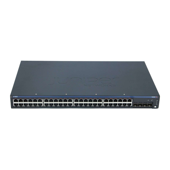
Page 19: Ex2200 Switch Overview
Rear Panel of an EX2200 Switch on page 7 EX2200 Switches First View EX2200 switches are available in models with 12 , 24, or 48 built-in network ports. The compact, fanless model, EX2200-C switches have 12 network ports. Copyright © 2015, Juniper Networks, Inc. -
Page 20: Uplink Ports
Each EX2200 switch except the EX2200-C switch model has an RJ-45 console port that accepts a cable with RJ-45 connector. The EX2200-C switch has two console ports: an RJ-45 port and a Mini-USB Type-B port. The RJ-45 console port accepts a cable with an RJ-45 connector and the Mini-USB Type-B console port accepts a Mini-B plug (5-pin) connector to connect to the console management device. -
Page 21: Cable Guard
Surface” on page Security Slots Each EX2200-C switch model has security slots on the left and right panels of the chassis. The security slots allow you to lock and secure the chassis in the installation site using a standard cable lock . See “Mounting an EX2200 Switch on a Desk or Other Level Surface”... -
Page 22: Front Panel Of An Ex2200 Switch
Complete Hardware Guide for EX2200 Ethernet Switches Front Panel of an EX2200 Switch The front panel of an EX2200 switch except the EX2200-C switch models consists of the following components: Network ports—depending on the switch model, either of: 24 or 48 10/100/1000BASE-T Gigabit Ethernet ports, with Power over Ethernet... -
Page 23: Rear Panel Of An Ex2200 Switch
Figure 4: Front Panel of an EX2200-C Switch with 12 Gigabit Ethernet Ports (non-PoE) Rear Panel of an EX2200 Switch The rear panel of the EX2200 switch except the EX2200-C switch models consists of the following components: Management Ethernet port USB port Copyright ©... -
Page 24: Figure 5: Rear Panel Of An Ex2200 Switch With Ac Power Supply
AC power cord inlet or DC power terminals Figure 5 on page 8 shows the rear panel of an EX2200 switch with an AC power supply. All EX2200 switches except the EX2200-C switch model have three exhaust openings on the rear panel. The two exhaust openings on the left have fans behind them and are open. -
Page 25: Ex2200 Switch Models
Site Preparation Checklist for EX2200 Switches on page 61 EX2200 Switch Models The EX2200 switch is available with 12, 24, or 48 built-in network ports with full Power over Ethernet (PoE) capability (all 12, 24, or 48 built-in network ports support PoE) or no PoE capability. -
Page 26: Ex2200 Switch Hardware And Cli Terminology Mapping
Installing and Connecting an EX2200 Switch on page 85 EX2200 Switch Hardware and CLI Terminology Mapping This topic describes the hardware terms used in EX2200 switch documentation and the corresponding terms used in the Junos OS command line interface (CLI). See... - Page 27 Chapter 1: EX2200 Switch Overview Table 5: CLI Equivalents of Terms Used in Documentation for EX2200 Switches (continued) Hardware Item (as Description (as Value (as displayed Item in Additional displayed in the CLI) displayed in the CLI) in the CLI)
- Page 28 Complete Hardware Guide for EX2200 Ethernet Switches Table 5: CLI Equivalents of Terms Used in Documentation for EX2200 Switches (continued) Hardware Item (as Description (as Value (as displayed Item in Additional displayed in the CLI) displayed in the CLI) in the CLI)
-
Page 29: Component Descriptions
Cooling System and Airflow in an EX2200 Switch on page 19 Chassis Status LEDs in EX2200 Switches The front panel of an EX2200 switch has two chassis status LEDs labeled SYS and ALM on the far right side of the panel. See... -
Page 30: Network Port And Uplink Port Leds In Ex2200 Switches
Understanding Alarm Types and Severity Levels on EX Series Switches Network Port and Uplink Port LEDs in EX2200 Switches Each network port and uplink port on the front panel of an EX2200 switch has two LEDs that indicate link/activity and port status. Each dual-purpose uplink port in an EX2200-C switch has two pairs of LEDs that indicate the link/activity status, one pair for each of the two ports that constitute the dual-purpose uplink port. -
Page 31: Figure 10: Leds On The Uplink Ports And Port Status Mode Leds In An Ex2200 Switch Except The Ex2200-C Switch Model
Port status mode LEDs Dual-purpose uplink ports Table 7 on page 15 describes the Link/Activity LED. Table 7: Link/Activity LED on the Network Ports and Uplink Ports in EX2200 Switches Color State and Description Link/Activity Green Blinking—The port and the link are active, and there is link activity. -
Page 32: Table 8: Status Led On The Network Ports, Uplink Ports, And Dual-Purpose Uplink Ports In Ex2200 Switches
Three blinks per second—1000 Mbps The speed indicators for uplink ports are: On steadily—1000 Mbps Off—10/100 Mbps The speed indicators for dual-purpose uplink ports of EX2200-C switch model are: One blink per second—10 Mbps Two blinks per second—100 Mbps Three blinks per second—1000 Mbps Duplex mode Indicates the duplex mode. -
Page 33: Management Port Leds In Ex2200 Switches
Configuring Gigabit Ethernet Interfaces (J-Web Procedure) Management Port LEDs in EX2200 Switches The management port on an EX2200 switch has two LEDs that indicate link/activity and port status. The EX2200 switches except the EX2200-C switch models have the management port on the rear panel and the EX2200-C switch has the management port on the front panel. -
Page 34: Power Supply In Ex2200 Switches
Power Supply in EX2200 Switches The power supply in EX2200 switches is built in along the rear panel of the chassis, with an AC power cord inlet or DC power terminals on the rear panel to connect power to the switch. -
Page 35: Cooling System And Airflow In An Ex2200 Switch
In the PoE models of these switches, there is an additional fan in the power supply. In the EX2200-C switch the cooling is done by the vents on top and sides of the chassis in non-PoE models and by heatsinks in PoE+ models. Do not block the vents on the chassis. -
Page 36: Airflow Direction In Poe Models Of Ex2200 Switches, Except For The Ex2200-C Models
Complete Hardware Guide for EX2200 Ethernet Switches Airflow Direction in PoE Models of EX2200 switches, Except for the EX2200-C Models Figure 15 on page 20 shows the airflow in PoE models of EX2200 switches, except EX2200-C models. Figure 15: Airflow Through PoE Models of EX2200 Switches Except the... -
Page 37: Component Specifications
USB Port Specifications for an EX Series Switch on page 21 Mini-USB Port Specifications for an EX2200 Switch on page 22 Network Port Connector Pinout Information for an EX2200 Switch on page 23 Console Port Connector Pinout Information for an EX Series Switch on page 23... -
Page 38: Mini-Usb Port Specifications For An Ex2200 Switch
Booting an EX Series Switch Using a Software Package Stored on a USB Flash Drive Mini-USB Port Specifications for an EX2200 Switch The EX2200-C switch, the compact, fanless model, has two management console ports: an RJ-45 port, and a Mini-USB Type-B port. -
Page 39: Network Port Connector Pinout Information For An Ex2200 Switch
Configuring the Console Port Type (CLI Procedure) Network Port Connector Pinout Information for an EX2200 Switch A network port on an EX2200 switch uses an RJ-45 connector to connect to a device. The port uses an autosensing RJ-45 connector to support a 10/100/1000Base-T connection. -
Page 40: Table 14: Ex Series Switches Console Port Connector Pinout Information
Complete Hardware Guide for EX2200 Ethernet Switches Table 14 on page 24 provides the pinout information for the RJ-45 console connector. An RJ-45 cable and an RJ-45 to DB-9 serial port adapter are supplied with the switch. NOTE: If your laptop or PC does not have a DB-9 male connector pin and you... -
Page 41: Rj-45 To Db-9 Serial Port Adapter Pinout Information For A Switch
Connecting and Configuring an OCX1100 Switch (CLI Procedure) Management Port Connector Pinout Information for an EX2200 Switch The management port on an EX2200 switch uses an RJ-45 connector to connect to a management device for out-of-band management. The port uses an autosensing RJ-45 connector to support a 10/100Base-T connection. -
Page 42: Pluggable Transceivers Supported On Ex2200 Switches
Connecting a Switch to a Network for Out-of-Band Management on page 127 Pluggable Transceivers Supported on EX2200 Switches Uplink ports and dual-purpose uplink ports on the front panel in EX2200 switches support SFP transceivers. This topic describes the optical interfaces supported for those transceivers. -
Page 43: Table 17: Optical Interface Support And Copper Interface Support For Gigabit Ethernet Sfp Transceivers In Ex2200 Switches Except Ex2200-C
(SMF) and multimode fiber-optic (MMF) cables and over the copper interface for SFP transceivers: Table 17 on page 27—Optical interface support and copper interface support for Gigabit Ethernet SFP transceivers in EX2200 switches except EX2200-C switches. Table 18 on page 46—Optical interface support for Fast Ethernet SFP transceivers except EX2200-C switches. - Page 44 Complete Hardware Guide for EX2200 Ethernet Switches Table 17: Optical interface Support and Copper Interface Support for Gigabit Ethernet SFP Transceivers in EX2200 Switches Except EX2200-C Switches (continued) Ethernet Standard Specification Value 1000BASE-SX Model number EX-SFP-1GE-SX Rate 1000 Mbps Connector type...
- Page 45 Chapter 3: Component Specifications Table 17: Optical interface Support and Copper Interface Support for Gigabit Ethernet SFP Transceivers in EX2200 Switches Except EX2200-C Switches (continued) Ethernet Standard Specification Value 1000BASE-LX Model number EX-SFP-1GE-LX Rate 1000 Mbps Connector type Fiber count...
- Page 46 Complete Hardware Guide for EX2200 Ethernet Switches Table 17: Optical interface Support and Copper Interface Support for Gigabit Ethernet SFP Transceivers in EX2200 Switches Except EX2200-C Switches (continued) Ethernet Standard Specification Value 1000BASE-BX-U Model number EX-SFP-GE10KT13R14 Rate 1000 Mbps Connector type...
- Page 47 Chapter 3: Component Specifications Table 17: Optical interface Support and Copper Interface Support for Gigabit Ethernet SFP Transceivers in EX2200 Switches Except EX2200-C Switches (continued) Ethernet Standard Specification Value 1000BASE-BX-D Model number EX-SFP-GE10KT14R13 Rate 1000 Mbps Connector type Fiber count...
- Page 48 Complete Hardware Guide for EX2200 Ethernet Switches Table 17: Optical interface Support and Copper Interface Support for Gigabit Ethernet SFP Transceivers in EX2200 Switches Except EX2200-C Switches (continued) Ethernet Standard Specification Value 1000BASE-BX-U Model number EX-SFP-GE10KT13R15 Rate 1000 Mbps Connector type...
- Page 49 Chapter 3: Component Specifications Table 17: Optical interface Support and Copper Interface Support for Gigabit Ethernet SFP Transceivers in EX2200 Switches Except EX2200-C Switches (continued) Ethernet Standard Specification Value 1000BASE-BX-D Model number EX-SFP-GE10KT15R13 Rate 1000 Mbps Connector type Fiber count...
- Page 50 Complete Hardware Guide for EX2200 Ethernet Switches Table 17: Optical interface Support and Copper Interface Support for Gigabit Ethernet SFP Transceivers in EX2200 Switches Except EX2200-C Switches (continued) Ethernet Standard Specification Value 1000BASE-BX-U Model number EX-SFP-GE40KT13R15 Rate 1000 Mbps Connector type...
- Page 51 Chapter 3: Component Specifications Table 17: Optical interface Support and Copper Interface Support for Gigabit Ethernet SFP Transceivers in EX2200 Switches Except EX2200-C Switches (continued) Ethernet Standard Specification Value 1000BASE-BX-D Model number EX-SFP-GE40KT15R13 Rate 1000 Mbps Connector type Fiber count...
- Page 52 Complete Hardware Guide for EX2200 Ethernet Switches Table 17: Optical interface Support and Copper Interface Support for Gigabit Ethernet SFP Transceivers in EX2200 Switches Except EX2200-C Switches (continued) Ethernet Standard Specification Value 1000BASE-LX Model number EX-SFP-1GE-LX40K Rate 1000 Mbps Connector type...
- Page 53 Chapter 3: Component Specifications Table 17: Optical interface Support and Copper Interface Support for Gigabit Ethernet SFP Transceivers in EX2200 Switches Except EX2200-C Switches (continued) Ethernet Standard Specification Value 1000BASE-LH (or Model number EX-SFP-1GE-LH 1000BASE-ZX) Rate 1000 Mbps Connector type...
- Page 54 Complete Hardware Guide for EX2200 Ethernet Switches Table 17: Optical interface Support and Copper Interface Support for Gigabit Ethernet SFP Transceivers in EX2200 Switches Except EX2200-C Switches (continued) Ethernet Standard Specification Value 1000BASE-LX Model number EX-SFP-GE80KCW1470 Rate 1000 Mbps Connector type...
- Page 55 Chapter 3: Component Specifications Table 17: Optical interface Support and Copper Interface Support for Gigabit Ethernet SFP Transceivers in EX2200 Switches Except EX2200-C Switches (continued) Ethernet Standard Specification Value 1000BASE-LX Model number EX-SFP-GE80KCW1490 Rate 1000 Mbps Connector type Fiber count...
- Page 56 Complete Hardware Guide for EX2200 Ethernet Switches Table 17: Optical interface Support and Copper Interface Support for Gigabit Ethernet SFP Transceivers in EX2200 Switches Except EX2200-C Switches (continued) Ethernet Standard Specification Value 1000BASE-LX Model number EX-SFP-GE80KCW1510 Rate 1000 Mbps Connector type...
- Page 57 Chapter 3: Component Specifications Table 17: Optical interface Support and Copper Interface Support for Gigabit Ethernet SFP Transceivers in EX2200 Switches Except EX2200-C Switches (continued) Ethernet Standard Specification Value 1000BASE-LX Model number EX-SFP-GE80KCW1530 Rate 1000 Mbps Connector type Fiber count...
- Page 58 Complete Hardware Guide for EX2200 Ethernet Switches Table 17: Optical interface Support and Copper Interface Support for Gigabit Ethernet SFP Transceivers in EX2200 Switches Except EX2200-C Switches (continued) Ethernet Standard Specification Value 1000BASE-LX Model number EX-SFP-GE80KCW1550 Rate 1000 Mbps Connector type...
- Page 59 Chapter 3: Component Specifications Table 17: Optical interface Support and Copper Interface Support for Gigabit Ethernet SFP Transceivers in EX2200 Switches Except EX2200-C Switches (continued) Ethernet Standard Specification Value 1000BASE-LX Model number EX-SFP-GE80KCW1570 Rate 1000 Mbps Connector type Fiber count...
- Page 60 Complete Hardware Guide for EX2200 Ethernet Switches Table 17: Optical interface Support and Copper Interface Support for Gigabit Ethernet SFP Transceivers in EX2200 Switches Except EX2200-C Switches (continued) Ethernet Standard Specification Value 1000BASE-LX Model number EX-SFP-GE80KCW1590 Rate 1000 Mbps Connector type...
- Page 61 Chapter 3: Component Specifications Table 17: Optical interface Support and Copper Interface Support for Gigabit Ethernet SFP Transceivers in EX2200 Switches Except EX2200-C Switches (continued) Ethernet Standard Specification Value 1000BASE-LX Model number EX-SFP-GE80KCW1610 Rate 1000 Mbps Connector type Fiber count...
-
Page 62: Table 18: Optical Interface Support For Fast Ethernet Sfp Transceivers In Ex2200 Switches Except Ex2200-C Switches
Complete Hardware Guide for EX2200 Ethernet Switches Table 18: Optical interface Support for Fast Ethernet SFP Transceivers in EX2200 Switches Except EX2200-C Switches Ethernet Standard Specification Value 100BASE-FX Model number EX-SFP-1FE-FX Rate 100 Mbps Connector type Fiber count Dual Transmitter wavelength... - Page 63 Chapter 3: Component Specifications Table 18: Optical interface Support for Fast Ethernet SFP Transceivers in EX2200 Switches Except EX2200-C Switches (continued) Ethernet Standard Specification Value 100BASE-LX Model number EX-SFP-1FE-LX Rate 100 Mbps Connector type Fiber count Dual Transmitter wavelength 1310 nm Minimum launch power –15 dBm...
- Page 64 Complete Hardware Guide for EX2200 Ethernet Switches Table 18: Optical interface Support for Fast Ethernet SFP Transceivers in EX2200 Switches Except EX2200-C Switches (continued) Ethernet Standard Specification Value 100BASE-BX-U Model number EX-SFP-FE20KT13R15 Rate 100 Mbps Connector type Fiber count Single...
- Page 65 Chapter 3: Component Specifications Table 18: Optical interface Support for Fast Ethernet SFP Transceivers in EX2200 Switches Except EX2200-C Switches (continued) Ethernet Standard Specification Value 100BASE-BX-D Model number EX-SFP-FE20KT15R13 Rate 100 Mbps Connector type Fiber count Single Transmitter wavelength 1550 nm...
- Page 66 Complete Hardware Guide for EX2200 Ethernet Switches Table 18: Optical interface Support for Fast Ethernet SFP Transceivers in EX2200 Switches Except EX2200-C Switches (continued) Ethernet Standard Specification Value 100BASE-LX40K Model number EX-SFP-1FE-LX40K Rate 100 Mbps Connector type Fiber count Dual...
- Page 67 Chapter 3: Component Specifications Table 18: Optical interface Support for Fast Ethernet SFP Transceivers in EX2200 Switches Except EX2200-C Switches (continued) Ethernet Standard Specification Value 100BASE-LH (or Model number EX-SFP-1FE-LH 100BASE-ZX) Rate 100 Mbps Connector type Fiber count Dual Transmitter wavelength...
-
Page 68: Table 19: Optical Interface Support And Copper Interface Support For Sfp
Complete Hardware Guide for EX2200 Ethernet Switches Table 19: Optical interface Support and Copper Interface Support for SFP Transceivers in EX2200-C Switches Ethernet Standard Specification Value 1000BASE-SX Model number EX-SFP-1GE-SX Rate 1000 Mbps Connector type Fiber count Dual Transmitter wavelength... - Page 69 Fiber type Core/Cladding size – Modal bandwidth – Transmitter wavelength 850 nm Distance 550 m (1804 ft) Software required Junos OS for EX Series switches, Release 11.3 or later Support for Virtual Chassis configuration Copyright © 2015, Juniper Networks, Inc.
- Page 70 Complete Hardware Guide for EX2200 Ethernet Switches Table 19: Optical interface Support and Copper Interface Support for SFP Transceivers in EX2200-C Switches (continued) Ethernet Standard Specification Value Extended Temp SFP Model number EX-SFP-1FE-FX-EX 100BASE-FX Rate 1000 Mbps Connector type Fiber count –...
- Page 71 Fiber type Core/Cladding size 62.5/125 µm Fiber grade FDDI/OM1 Modal bandwidth 500 MHz/km Distance 2 km (1.2 miles) Software required Junos OS for EX Series switches, Release 11.3 or later Support for Virtual Chassis configuration Copyright © 2015, Juniper Networks, Inc.
- Page 72 Complete Hardware Guide for EX2200 Ethernet Switches Table 19: Optical interface Support and Copper Interface Support for SFP Transceivers in EX2200-C Switches (continued) Ethernet Standard Specification Value 1000BASE-LX Model number EX-SFP-1GE-LX Rate 1000 Mbps Connector type Fiber count Dual Transmitter wavelength...
- Page 73 Junos OS for EX Series switches, Release 11.3 or later Support for Virtual Chassis configuration Related EX2200 Switches Hardware Overview on page 3 Documentation Installing a Transceiver in an EX Series Switch on page 113 Removing a Transceiver from a Switch on page 149...
- Page 74 Complete Hardware Guide for EX2200 Ethernet Switches Copyright © 2015, Juniper Networks, Inc.
- Page 75 PART 2 Planning for Switch Installation Site Preparation on page 61 Mounting and Clearance Requirements on page 71 Cable Specifications on page 77 Planning Power Requirements on page 79 Copyright © 2015, Juniper Networks, Inc.
- Page 76 Complete Hardware Guide for EX2200 Ethernet Switches Copyright © 2015, Juniper Networks, Inc.
-
Page 77: Site Preparation
CHAPTER 4 Site Preparation Site Preparation Checklist for EX2200 Switches on page 61 General Site Guidelines on page 62 Site Electrical Wiring Guidelines on page 63 Environmental Requirements and Specifications for EX Series Switches on page 65 Site Preparation Checklist for EX2200 Switches... -
Page 78: General Site Guidelines
General Safety Guidelines and Warnings on page 169 Documentation General Site Guidelines on page 62 Installing and Connecting an EX2200 Switch on page 85 Mounting an EX2200 Switch on page 88 General Site Guidelines This topic applies to hardware devices in the EX Series product family, which includes EX Series switches, the EX Series Redundant Power System (RPS), and the XRE200 External Routing Engine. -
Page 79: Site Electrical Wiring Guidelines
Table 21 on page 64 describes the factors you must consider while planning the electrical wiring at your site. WARNING: It is particularly important to provide a properly grounded and shielded environment and to use electrical surge-suppression devices. Copyright © 2015, Juniper Networks, Inc. -
Page 80: Table 21: Site Electrical Wiring Guidelines
Documentation General Electrical Safety Guidelines and Warnings on page 197 Prevention of Electrostatic Discharge Damage on page 198 Power Supply in EX2200 Switches on page 18 Power Supply in EX3200 Switches Power Supply in EX3300 Switches Power Supply in EX4200 Switches... -
Page 81: Environmental Requirements And Specifications For Ex Series Switches
Table 22 on page 66 provides the required environmental conditions for normal switch operation. Copyright © 2015, Juniper Networks, Inc. -
Page 82: Table 22: Ex Series Switch Environmental Tolerances
Complete Hardware Guide for EX2200 Ethernet Switches Table 22: EX Series Switch Environmental Tolerances Environment Tolerance Switch or device Altitude Relative Humidity Temperature Seismic EX2200-C No performance Normal operation ensured Normal operation ensured in the Complies with Zone 4 degradation up to in relative humidity range of temperature range 32°... - Page 83 10,000 feet (3048 5% through 90% 104° F (0° C through 40° C) requirements as per meters) (noncondensing) GR-63. Nonoperating storage temperature in shipping container: –40° F (–40° C) to 158° F (70° C) Copyright © 2015, Juniper Networks, Inc.
- Page 84 Articles 110–16, 110–17, and 110–18 of the National Electrical Code, ANSI/NFPA 70. Related Clearance Requirements for Airflow and Hardware Maintenance for EX2200 Switches Documentation on page 74 Clearance Requirements for Airflow and Hardware Maintenance for EX3200 Switches...
- Page 85 Clearance Requirements for Airflow and Hardware Maintenance for an EX8216 Switch Clearance Requirements for Airflow and Hardware Maintenance for an EX9204 Switch Clearance Requirements for Airflow and Hardware Maintenance for an EX9208 Switch Clearance Requirements for Airflow and Hardware Maintenance for an EX9214 Switch Copyright © 2015, Juniper Networks, Inc.
- Page 86 Complete Hardware Guide for EX2200 Ethernet Switches Copyright © 2015, Juniper Networks, Inc.
-
Page 87: Mounting And Clearance Requirements
Rack Requirements for EX2200 Switches on page 71 Cabinet Requirements for EX2200 Switches on page 72 Requirements for Mounting an EX2200 Switch on a Desktop or Wall on page 73 Clearance Requirements for Airflow and Hardware Maintenance for EX2200 Switches on page 74 Rack Requirements for EX2200 Switches You can mount the EX2200 switches on two-post racks or four-post racks. -
Page 88: Cabinet Requirements For Ex2200 Switches
Mounting an EX2200 Switch on Two Posts of a Rack or Cabinet on page 95 Mounting an EX2200 Switch on Four Posts of a Rack or Cabinet on page 98 Mounting an EX2200 Switch in a Recessed Position in a Rack or Cabinet on page 102 Cabinet Requirements for EX2200 Switches You can mount the switch in a cabinet that contains a 19-in. -
Page 89: Requirements For Mounting An Ex2200 Switch On A Desktop Or Wall
Mounting an EX2200 Switch on Four Posts of a Rack or Cabinet on page 98 Mounting an EX2200 Switch in a Recessed Position in a Rack or Cabinet on page 102 Requirements for Mounting an EX2200 Switch on a Desktop or Wall You can install the switch on a desktop or wall. -
Page 90: Switches
Insert the screws into wall studs wherever possible to provide added support for the chassis. Use the wall-mount kit from Juniper Networks to mount the switch on a wall. The wall-mount kit is not part of the standard package and must be ordered separately. -
Page 91: Figure 17: Clearance Requirements For Airflow And Hardware Maintenance For
For the cooling system to function properly, the airflow around the chassis must be unrestricted. Figure 18 on page 75 shows the airflow in PoE models of EX2200 switches, except for EX2200-C models. Figure 19 on page 76 shows the airflow non-PoE models of EX2200 switches, except for EX2200-C models. -
Page 92: Figure 19: Airflow Through Non-Poe Models Of Ex2200 Switches Except Ex2200-C Switch Models
Fans Chassis rear If you are mounting an EX2200 switch in a rack or cabinet with other equipment, or if you are placing it on the desktop or floor near other equipment, ensure that the exhaust from other equipment does not blow into the intake vents of the chassis. -
Page 93: Cable Specifications
Fiber-Optic Cable to a Switch” on page 133. Related Management Port Connector Pinout Information for an EX2200 Switch on page 25 Documentation Console Port Connector Pinout Information for an EX Series Switch on page 23 EX2200 Switches Hardware Overview on page 3... - Page 94 Complete Hardware Guide for EX2200 Ethernet Switches Copyright © 2015, Juniper Networks, Inc.
-
Page 95: Planning Power Requirements
AC Power Cord Specifications for EX2200 Switches on page 80 Power Specifications for EX2200 Switches This topic describes the power supply electrical specifications for EX2200 switches. Table 25 on page 79 provides the AC power supply electrical specifications for EX2200 switches. -
Page 96: Ac Power Cord Specifications For Ex2200 Switches
Complete Hardware Guide for EX2200 Ethernet Switches NOTE: EX2200 switches with DC power supply do not provide PoE. NOTE: For DC power supplies, we recommend that you provide at least 3.5 A at 48 VDC and use a facility circuit breaker rated for 10 A minimum. Doing so... -
Page 97: Figure 20: Ac Plug Types
Table 27 on page Figure 20: AC Plug Types Related Power Supply in EX2200 Switches on page 18 Documentation General Safety Guidelines and Warnings on page 169 General Electrical Safety Guidelines and Warnings on page 197 Prevention of Electrostatic Discharge Damage on page 198... - Page 98 Complete Hardware Guide for EX2200 Ethernet Switches Copyright © 2015, Juniper Networks, Inc.
-
Page 99: Installing And Connecting The Switch And Switch Components
PART 3 Installing and Connecting the Switch and Switch Components Installing the Switch on page 85 Installing Switch Components on page 113 Connecting the Switch on page 117 Performing Initial Configuration on page 135 Copyright © 2015, Juniper Networks, Inc. - Page 100 Complete Hardware Guide for EX2200 Ethernet Switches Copyright © 2015, Juniper Networks, Inc.
-
Page 101: Installing The Switch
Mounting an EX2200 Switch on Four Posts of a Rack or Cabinet on page 98 Mounting an EX2200 Switch in a Recessed Position in a Rack or Cabinet on page 102 Mounting an EX2200 Switch on a Wall on page 102... -
Page 102: Unpacking An Ex2200 Switch
Complete Hardware Guide for EX2200 Ethernet Switches “Mounting an EX2200 Switch On or Under a Desk Using Screws” on page 92 (using the desk/wall mounting screws) “Mounting an EX2200 Switch Using the Magnet Mount” on page 109 (using the separately orderable magnet sheet) Follow instructions in “Connecting Earth Ground to an EX Series Switch”... -
Page 103: Parts Inventory (Packing List) For An Ex2200 Switch
Connecting and Configuring an EX Series Switch (J-Web Procedure) on page 142 Parts Inventory (Packing List) for an EX2200 Switch The EX2200 switches are shipped in a cardboard carton, secured with foam packing material. The carton also contains an accessory box. -
Page 104: Mounting An Ex2200 Switch
Table 28: Parts List for EX2200 Switches (continued) Component Quantity RJ-45 cable and RJ-45 to DB-9 serial port adapter Cable guard and 3 number-8 Phillips truss-head screws (EX2200-C models only and separately orderable) Quick Start installation instructions Juniper Networks Product Warranty End User License Agreement... -
Page 105: Mounting An Ex2200 Switch On A Desk Or Other Level Surface
Mounting an EX2200 Switch on a Desk or Other Level Surface You can mount an EX2200 switch on a desk or other level surface by using the four rubber feet that are shipped with the switch. The rubber feet stabilize the chassis. -
Page 106: Figure 21: Attaching Rubber Feet To A Switch Chassis
“Chassis Lifting Guidelines for EX2200 Switches” on page 183. NOTE: Do not block the vents on the top of the EX2200-C switches. Doing this can lead to overheating of the switch chassis. Ensure that you have the following parts and tools available:... -
Page 107: Figure 22: Attaching A Cable Guard To An Ex2200-C Switch
Figure 22 on page Figure 22: Attaching a Cable Guard to an EX2200-C Switch (Optional; applies only to EX2200-C models) Attach the standard cable lock to the security slots on the both sides of the switch: Rope the cable to a desk or a rack and set the lock to unlocked position. -
Page 108: Mounting An Ex2200 Switch On Or Under A Desk Using Screws
This topic applies only to the EX2200-C switch, the compact, fanless model. You can mount an EX2200-C switch on or under a desk or other level surface by using the flexible mounting slots on the bottom of the chassis to secure the switch. -
Page 109: Figure 24: Measurements For Installing Mounting Screws For Ex2200-C
Chapter 8: Installing the Switch Figure 24: Measurements for Installing Mounting Screws for EX2200-C Switch Drill hole A and install a mounting screw. Drill hole B 9.52 in. (22.1 cm) on a level line from hole A and install a mounting screw. -
Page 110: Figure 25: Mounting The Ex2200-C Switch On Or Under A Desk Using Screws
Complete Hardware Guide for EX2200 Ethernet Switches Figure 25: Mounting the EX2200-C Switch On or Under a Desk Using Screws (Optional) Attach the cable guard to protect cable connections: Use the 3 truss-head screws to attach the cable guard to the bottom of the chassis. -
Page 111: Mounting An Ex2200 Switch On Two Posts Of A Rack Or Cabinet
Mounting an EX2200 Switch on Two Posts of a Rack or Cabinet You can mount all EX2200 switches on two posts of a two-post or a four-post 19-in. rack or cabinet using the mounting brackets and screws provided with all EX2200 switches except the EX2200-C switches. - Page 112 Screws to secure the chassis to the rack (not provided) 2-in.-recess front brackets from the separately orderable four-post rack-mount kit if you will mount the switch in a recessed position (not applicable for EX2200-C switches). NOTE: One person must be available to lift the switch while another secures the switch to the rack.
-
Page 113: Figure 28: Attaching The Mounting Bracket Along The Front Of The Switch
Chapter 8: Installing the Switch To mount the switch on two posts of a two-post or a four-post rack: Remove the switch from the shipping carton (see “Unpacking an EX2200 Switch” on page 86). Place the switch on a flat, stable surface. -
Page 114: Mounting An Ex2200 Switch On Four Posts Of A Rack Or Cabinet
Connecting and Configuring an EX Series Switch (CLI Procedure) on page 139 Connecting and Configuring an EX Series Switch (J-Web Procedure) on page 142 Mounting an EX2200 Switch in a Recessed Position in a Rack or Cabinet on page 102 Rack-Mounting and Cabinet-Mounting Warnings on page 184... - Page 115 Chapter 8: Installing the Switch NOTE: If you need to mount an EX2200 switch except the EX2200-C switch model in a recessed position on either a two-post rack or a four-post rack, you can use the 2-in.-recess front-mounting brackets provided in the separately orderable four-post rack-mount kit.
-
Page 116: Figure 30: Attaching The Front-Mounting Bracket To The Side Mounting-Rail
Complete Hardware Guide for EX2200 Ethernet Switches Figure 30: Attaching the Front-Mounting Bracket to the Side Mounting-Rail 1— Side mounting-rail 2— Front-mounting bracket Place the switch on a flat, stable surface. Align the side mounting-rails along the side panels of the switch chassis. Align the two holes in the rear of the side mounting-rails with the two holes on the rear of the side panel. -
Page 117: Figure 32: Mounting The Switch To The Front Posts Of A Rack
Related Mounting an EX2200 Switch on Two Posts of a Rack or Cabinet on page 95 Documentation Connecting Earth Ground to an EX Series Switch on page 117... -
Page 118: Mounting An Ex2200 Switch In A Recessed Position In A Rack Or Cabinet
Connecting and Configuring an EX Series Switch (CLI Procedure) on page 139 Connecting and Configuring an EX Series Switch (J-Web Procedure) on page 142 Mounting an EX2200 Switch in a Recessed Position in a Rack or Cabinet on page 102 Rack-Mounting and Cabinet-Mounting Warnings on page 184... - Page 119 Chapter 8: Installing the Switch When mounting an EX2200 switch chassis in a vertical position, orient the front panel of the chassis downward to ensure proper airflow and meet safety requirements in the event of a fire. When wall mounting Power over Ethernet (PoE) models (EX2200-24P...
-
Page 120: Figure 34: Attaching Wall-Mount Brackets To A Switch Chassis
Complete Hardware Guide for EX2200 Ethernet Switches Figure 34: Attaching Wall-Mount Brackets to a Switch Chassis Baffle for PoE Models (EX2200-24P and EX2200-48P) Rear panel Front panel If you are mounting two switches together, align the second switch on top of the first and attach it to the mounting brackets using two additional wall-mount bracket screws on each side. -
Page 121: Mounting An Ex2200-C Switch On A Wall
Mounting an EX2200-C Switch on a Wall You can mount an EX2200-C switch, the compact, fanless model, on a wall by using the flexible mounting slots on the bottom of the chassis to fix to the screws on the wall. - Page 122 NOTE: Do not block the vents on the top of the EX2200-C switches. Doing this can lead to overheating of the switch chassis. Before mounting the switch on a wall: Verify that the site meets the requirements described in “Site Preparation Checklist...
-
Page 123: Figure 37: Measurements For Installing Mounting Screws For The Ex2200-C
Chapter 8: Installing the Switch Figure 37: Measurements for Installing Mounting Screws for the EX2200-C Switch Drill hole A and install a mounting screw. Drill hole B 9.53 in. (24.2 cm) on a level line from hole A and install a mounting screw. -
Page 124: Figure 38: Mounting The Ex2200-C Switch On A Wall Using Screws
Complete Hardware Guide for EX2200 Ethernet Switches Figure 38: Mounting the EX2200-C Switch on a Wall Using Screws (Optional) Attach the optional cable guard to protect cable connections: Use the 3 truss-head screws to attach the cable guard to the bottom of the chassis. -
Page 125: Mounting An Ex2200 Switch Using The Magnet Mount
Mounting an EX2200 Switch Using the Magnet Mount This topic applies only to the EX2200-C switch, the compact, fanless model. You can mount an EX2200-C switch on or under a surface made of ferrous material using the separately orderable magnet sheet. - Page 126 Read “General Safety Guidelines and Warnings” on page 169, with particular attention “Chassis Lifting Guidelines for EX2200 Switches” on page 183. Remove the switch from the shipping carton (see “Unpacking an EX2200 Switch” on page 86).
-
Page 127: Figure 41: Mounting An Ex2200-C Switch Using Magnet Mount
Chapter 8: Installing the Switch Figure 41: Mounting an EX2200-C Switch Using Magnet Mount Magnetic surface Magnet mount (Optional) Attach the cable guard to protect cable connections: Use the 3 truss-head screws to attach the cable guard to the bottom of the chassis. -
Page 128: Figure 42: Attaching A Cable Guard To An Ex2200-C Switch
Complete Hardware Guide for EX2200 Ethernet Switches Figure 42: Attaching a Cable Guard to an EX2200-C Switch (Optional) Attach the standard cable lock to the security slots on the both sides of the switch Rope the cable to a desk or a rack and set the lock to unlocked position. -
Page 129: Installing Switch Components
CAUTION: If you are having a problem running a Juniper Networks device that is using a third-party optic or cable, the Juniper Networks Technical Assistance Center (JTAC) can help you diagnose the source of the problem. Your JTAC engineer might recommend that you check the third-party optic or cable and potentially replace it with an equivalent Juniper Networks optic or cable that is qualified for the device. - Page 130 Complete Hardware Guide for EX2200 Ethernet Switches Before you begin installing a transceiver in an EX Series switch, ensure that you have taken the necessary precautions for safe handling of lasers (see “Laser and LED Safety Guidelines and Warnings for Switches” on page 175).
-
Page 131: Figure 44: Installing A Transceiver In An Ex Series Switch
Figure 44: Installing a Transceiver in an EX Series Switch 1— Ejector lever Related Removing a Transceiver from a Switch on page 149 Documentation Connecting a Fiber-Optic Cable to a Switch on page 133 Pluggable Transceivers Supported on EX Series Switches Copyright © 2015, Juniper Networks, Inc. - Page 132 Complete Hardware Guide for EX2200 Ethernet Switches Copyright © 2015, Juniper Networks, Inc.
-
Page 133: Connecting The Switch
Connecting a Switch to a Network for Out-of-Band Management on page 127 Connecting a Switch to a Management Console on page 129 Connecting an EX2200 Switch to a Management Console Using Mini-USB Type-B Console Port on page 131 Connecting a Fiber-Optic Cable to a Switch on page 133... -
Page 134: Parts And Tools Required For Connecting An Ex Series Switch To Earth Ground
Complete Hardware Guide for EX2200 Ethernet Switches Parts and Tools Required for Connecting an EX Series Switch to Earth Ground Table 30 on page 118 lists the earthing terminal location, grounding cable requirements, grounding lug specifications, screws and washers required, and the screwdriver needed for connecting a switch to earth ground. - Page 135 Two ¼-20 Phillips (+) chassis minimum 60°C wire, LCD2-14A-Q or x 0.5 in. screws number 2 or as permitted by equivalent with #¼” the local code —provided split-washer —provided Two #¼” flat washers— provided Copyright © 2015, Juniper Networks, Inc.
-
Page 136: Switch
Special Instructions EX3200 NOTE: Some early variants of EX3200 switches for which the Juniper Networks model number on the label next to the protective earthing terminal is from 750-021xxx through 750-030xxx require 10-24x.25 in. screws. Copyright © 2015, Juniper Networks, Inc. -
Page 137: Figure 45: Connecting The Grounding Lug To A Switch Mounted On Four Posts Of
Special Instructions EX4200 NOTE: Some early variants of EX4200 switches for which the Juniper Networks model number on the label next to the protective earthing terminal is from 750-021xxx through 750-030xxx require 10-24x.25 in. screws. NOTE: The protective earthing terminal on an EX4200 switch mounted on four posts of a rack is accessible through the slot on the left rear bracket only if the rack is 27.5 in. -
Page 138: Connecting Earth Ground To An Ex Series Switch
Ensure that the cable does not drape where people could trip over it. Related Connecting AC Power to an EX2200 Switch on page 123 Documentation Connecting DC Power to an EX2200 Switch on page 125 Connecting AC Power to an EX3200 Switch... -
Page 139: Connecting Ac Power To An Ex2200 Switch
Grounded Equipment Warning on page 189 Connecting AC Power to an EX2200 Switch The power supply in an EX2200 switch is located on the rear panel. Ensure that you have the following parts and tools available: A power cord appropriate for your geographical location A power cord retainer clip Ensure that you have connected the switch chassis to earth ground. -
Page 140: Figure 47: Connecting An Ac Power Cord Retainer Clip To The Ac Power Cord Inlet On An Ex2200 Switch
Complete Hardware Guide for EX2200 Ethernet Switches To connect AC power to the switch: Squeeze the two sides of the power cord retainer clip and insert the L-shaped ends of the wire clip into the holes in the bracket on each side of the AC power cord inlet... -
Page 141: Connecting Dc Power To An Ex2200 Switch
Connecting and Configuring an EX Series Switch (CLI Procedure) on page 139 Documentation Connecting and Configuring an EX Series Switch (J-Web Procedure) on page 142 Power Supply in EX2200 Switches on page 18 Connecting DC Power to an EX2200 Switch The power supply is built in along the rear panel. -
Page 142: Figure 49: Securing Ring Lugs To The Terminals On The Dc Power Supply
Complete Hardware Guide for EX2200 Ethernet Switches Ensure that you have the following parts and tools available: DC power source cables (14 AWG) with ring lug (Molex 0190700067 or equivalent) (not provided) attached to them by a licensed electrician Phillips (+) screwdriver, number 2... -
Page 143: Connecting A Switch To A Network For Out-Of-Band Management
Documentation Connecting and Configuring an EX Series Switch (J-Web Procedure) on page 142 Power Supply in EX2200 Switches on page 18 Connecting a Switch to a Network for Out-of-Band Management This topic applies to multiple hardware devices in the EX Series product family, which includes EX Series switches and the XRE200 External Routing Engine. -
Page 144: Figure 50: Ethernet Cable Connector
Complete Hardware Guide for EX2200 Ethernet Switches Ensure that you have an Ethernet cable with an RJ-45 connector available. One such cable is provided with the device. Figure 50 on page 128 shows the RJ-45 connector of the Ethernet cable supplied with the device. -
Page 145: Connecting A Switch To A Management Console
Connecting a Switch to a Management Console on page 129 Documentation Management Port Connector Pinout Information for an EX2200 Switch on page 25 Management Port Connector Pinout Information for an EX3200 Switch Management Port Connector Pinout Information for an EX3300 Switch... -
Page 146: Figure 52: Ethernet Cable Connector
Complete Hardware Guide for EX2200 Ethernet Switches to the management console or to a console server. The console port accepts a cable with an RJ-45 connector. Ensure that you have an Ethernet cable with an RJ-45 connector available. An RJ-45 cable and an RJ-45 to DB-9 serial port adapter are supplied with the device. -
Page 147: Connecting An Ex2200 Switch To A Management Console Using Mini-Usb Type-B Console Port
If your laptop or PC does not have a DB-9 male connector pin or RJ-45 connector pin, you can connect your laptop or PC directly to an EX2200–C switch using a mini-USB cable that has a Standard-A USB connector on one end and a Mini-USB Type-B (5 pin) connector on the other end. - Page 148 Complete Hardware Guide for EX2200 Ethernet Switches For information about configuring and managing an EX2200–C switch using the RJ-45 console port, see “Connecting a Switch to a Management Console” on page 129. Before you begin connecting an EX2200–C switch using Mini-USB Type-B console port: Ensure that the USB to Serial driver is installed on the host machine.
-
Page 149: Connecting A Fiber-Optic Cable To A Switch
Do not let fiber-optic cables hang free from the connector. Do not allow fastened loops of cables to dangle, which stresses the cables at the fastening point. Copyright © 2015, Juniper Networks, Inc. - Page 150 Complete Hardware Guide for EX2200 Ethernet Switches Related Disconnecting a Fiber-Optic Cable from a Switch on page 152 Documentation Installing a Transceiver in an EX Series Switch on page 113 Maintaining Fiber-Optic Cables in Switches on page 155 Pluggable Transceivers Supported on EX Series Switches...
-
Page 151: Performing Initial Configuration
See Reverting to the Default Factory Configuration for the EX Series Switch. The following factory default configuration file is for an EX2200 switch with 24 ports, all of which have PoE capability:... - Page 152 Complete Hardware Guide for EX2200 Ethernet Switches file messages { any notice; authorization info; file interactive-commands { interactive-commands any; commit { factory-settings { reset-chassis-lcd-menu; reset-virtual-chassis-configuration; interfaces { ge-0/0/0 { unit 0 { family ethernet-switching; ge-0/0/1 { unit 0 { family ethernet-switching;...
- Page 153 { unit 0 { family ethernet-switching; ge-0/0/15 { unit 0 { family ethernet-switching; ge-0/0/16 { unit 0 { family ethernet-switching; ge-0/0/17 { unit 0 { family ethernet-switching; ge-0/0/18 { unit 0 { family ethernet-switching; Copyright © 2015, Juniper Networks, Inc.
- Page 154 Complete Hardware Guide for EX2200 Ethernet Switches ge-0/0/19 { unit 0 { family ethernet-switching; ge-0/0/20 { unit 0 { family ethernet-switching; ge-0/0/21 { unit 0 { family ethernet-switching; ge-0/0/22 { unit 0 { family ethernet-switching; ge-0/0/23 { unit 0 { family ethernet-switching;...
-
Page 155: Connecting And Configuring An Ex Series Switch (Cli Procedure)
There are two ways to connect and configure an EX Series switch: one method is through the console by using the CLI and the other is by using the J-Web interface. NOTE: EX2200-24T-4G-DC switches do not support switch connection and configuration through the J-Web interface. This topic describes the CLI procedure. - Page 156 See Switch Fabric and Routing Engine (SRE) Module in an EX8208 Switch. See Routing Engine (RE) Module in an EX8216 Switch. NOTE: In EX2200-C, EX4300, and EX4550 switches, you can also use the Mini-USB Type-B console port to connect to a laptop or PC. For EX2200-C switches, see “Connecting an EX2200 Switch to a...
- Page 157 Related Connecting and Configuring an EX Series Switch (J-Web Procedure) on page 142 Documentation Installing and Connecting an EX2200 Switch on page 85 Installing and Connecting an EX3200 Switch Installing and Connecting an EX3300 Switch Installing and Connecting an EX4200 Switch...
-
Page 158: Connecting And Configuring An Ex Series Switch (J-Web Procedure)
The switch exits EZSetup after 10 minutes and reverts to the factory default configuration, and the PC loses connectivity to the switch. EX2200 and EX2200-C switch—The LEDs on the network ports on the front panel blink when the switch is in the initial setup mode. - Page 159 To connect and configure the switch by using the J-Web interface: Transition the switch into initial setup mode: EX2200 and EX2200-C switch—Press the mode button located on the lower right corner of the front panel for 10 seconds. EX3200, EX3300, EX4200, EX4300, EX4500, EX4550, EX6200, or EX8200 switch—Use the...
- Page 160 Complete Hardware Guide for EX2200 Ethernet Switches EX6200 switch—Connect the cable to one of the ports labeled on the Switch MGMT Fabric and Routing Engine (SRE) module in slot 4 or 5 in an EX6210 switch. EX8200 switch—Connect the cable to the port labeled...
- Page 161 Related Connecting and Configuring an EX Series Switch (CLI Procedure) on page 139 Documentation Installing and Connecting an EX2200 Switch on page 85 Installing and Connecting an EX3200 Switch Installing and Connecting an EX3300 Switch Installing and Connecting an EX4200 Switch...
- Page 162 Complete Hardware Guide for EX2200 Ethernet Switches Copyright © 2015, Juniper Networks, Inc.
-
Page 163: Removing Switch Components
PART 4 Removing Switch Components Removing Switch Components on page 149 Copyright © 2015, Juniper Networks, Inc. - Page 164 Complete Hardware Guide for EX2200 Ethernet Switches Copyright © 2015, Juniper Networks, Inc.
-
Page 165: Removing Switch Components
Label the cable connected to the transceiver so that you can reconnect it correctly. WARNING: Do not look directly into a fiber-optic transceiver or into the ends of fiber-optic cables. Fiber-optic transceivers and fiber-optic cables connected to transceivers emit laser light that can damage your eyes. Copyright © 2015, Juniper Networks, Inc. - Page 166 Complete Hardware Guide for EX2200 Ethernet Switches WARNING: Do not leave a fiber-optic transceiver uncovered except when inserting or removing a cable. The rubber safety cap keeps the port clean and prevents accidental exposure to laser light. CAUTION: Do not bend fiber-optic cables beyond their minimum bend radius.
-
Page 167: Figure 58: Removing A Transceiver From A Switch
Place the transceiver in the antistatic bag or on the antistatic mat placed on a flat, stable surface. Place the dust cover over the empty port. Related Installing a Transceiver in an EX Series Switch on page 113 Documentation Pluggable Transceivers Supported on EX Series Switches Copyright © 2015, Juniper Networks, Inc. -
Page 168: Disconnecting A Fiber-Optic Cable From A Switch
Complete Hardware Guide for EX2200 Ethernet Switches Installing a Transceiver in an OCX1100 Switch Pluggable Transceivers Supported on OCX1100 Switches Disconnecting a Fiber-Optic Cable from a Switch EX Series switches and OCX1100 switches have field-replaceable unit (FRU) optical transceivers to which you can connect fiber-optic cables. -
Page 169: Switch And Component Maintenance
PART 5 Switch and Component Maintenance Routine Maintenance on page 155 Copyright © 2015, Juniper Networks, Inc. - Page 170 Complete Hardware Guide for EX2200 Ethernet Switches Copyright © 2015, Juniper Networks, Inc.
-
Page 171: Routine Maintenance
After cleaning the transceiver, make sure that the connector tip of the fiber-optic cable is clean. Use only an approved alcohol-free fiber-optic cable cleaning kit such ® as the Opptex Cletop-S Fiber Cleaner. Follow the directions in the cleaning kit you use. Copyright © 2015, Juniper Networks, Inc. - Page 172 Complete Hardware Guide for EX2200 Ethernet Switches Related Connecting a Fiber-Optic Cable to a Switch on page 133 Documentation Laser and LED Safety Guidelines and Warnings for Switches on page 175 Pluggable Transceivers Supported on EX Series Switches Pluggable Transceivers Supported on OCX1100 Switches...
-
Page 173: Returning Hardware
PART 6 Returning Hardware Returning the Switch or Switch Components on page 159 Copyright © 2015, Juniper Networks, Inc. - Page 174 Complete Hardware Guide for EX2200 Ethernet Switches Copyright © 2015, Juniper Networks, Inc.
-
Page 175: Returning The Switch Or Switch Components
Packing an EX2200 Switch or Component for Shipping on page 163 Returning an EX2200 Switch or Component for Repair or Replacement If you need to return an EX2200 switch or hardware component to Juniper Networks for repair or replacement, follow this procedure: Determine the serial number of the component. -
Page 176: Locating The Serial Number On An Ex2200 Switch Or Component
PS 550W AC Fan Tray Fan Tray Locating the Chassis Serial Number ID Label on an EX2200 Switch EX2200 switches have serial number ID labels located on the rear panel of the chassis (see Figure 59 on page 161). Copyright © 2015, Juniper Networks, Inc. -
Page 177: Contacting Customer Support To Obtain Return Materials Authorization For Switches
Returning an EX2200 Switch or Component for Repair or Replacement on page 159 Contacting Customer Support to Obtain Return Materials Authorization for Switches If you are returning a switch or hardware component to Juniper Networks for repair or replacement, obtain a Return Materials Authorization (RMA) from Juniper Networks Technical Assistance Center (JTAC). - Page 178 The support representative validates your request and issues an RMA number for return of the component. Related Packing an EX2200 Switch or Component for Shipping on page 163 Documentation Packing an EX3200 Switch or Component for Shipping Packing an EX3300 Switch or Component for Shipping...
-
Page 179: Packing An Ex2200 Switch Or Component For Shipping
Returning an OCX1100 Switch or Component for Repair or Replacement Packing an EX2200 Switch or Component for Shipping If you are returning an EX2200 switch or component to Juniper Networks for repair or replacement, pack the item as described in this topic. -
Page 180: Packing A Switch For Shipping
Complete Hardware Guide for EX2200 Ethernet Switches Packing a Switch for Shipping To pack a switch for shipping: On the console or other management device connected to the switch, enter the CLI operational mode and issue the following command to shut down the switch software: user@switch>... - Page 181 Chapter 14: Returning the Switch or Switch Components Related Returning an EX2200 Switch or Component for Repair or Replacement on page 159 Documentation Copyright © 2015, Juniper Networks, Inc.
- Page 182 Complete Hardware Guide for EX2200 Ethernet Switches Copyright © 2015, Juniper Networks, Inc.
-
Page 183: Safety Information
PART 7 Safety Information General Safety Information on page 169 Radiation and Laser Warnings on page 175 Installation and Maintenance Safety Information on page 181 Power and Electrical Safety Information on page 197 Copyright © 2015, Juniper Networks, Inc. - Page 184 Complete Hardware Guide for EX2200 Ethernet Switches Copyright © 2015, Juniper Networks, Inc.
-
Page 185: General Safety Information
Do not perform any actions that create a potential hazard to people or make the equipment unsafe. Never attempt to lift an object that is too heavy for one person to handle. Never install or manipulate wiring during electrical storms. Copyright © 2015, Juniper Networks, Inc. -
Page 186: Definitions Of Safety Warning Levels
Complete Hardware Guide for EX2200 Ethernet Switches Never install electrical jacks in wet locations unless the jacks are specifically designed for wet environments. Operate the device only when it is properly grounded. Ensure that the separate protective earthing terminal provided on this device is permanently connected to earth. - Page 187 å unngå ulykker. Aviso Este símbolo de aviso indica perigo. Encontra-se numa situação que lhe poderá causar danos físicos. Antes de começar a trabalhar com qualquer equipamento, familiarize-se com os perigos relacionados com circuitos Copyright © 2015, Juniper Networks, Inc.
-
Page 188: Fire Safety Requirements
In addition, you should establish procedures to protect your equipment in the event of a fire emergency. Juniper Networks products should be installed in an environment suitable for electronic equipment. We recommend that fire suppression equipment be available in the event of a fire in the vicinity of the equipment and that all local fire, safety, and electrical codes and ordinances be observed when you install and operate your equipment. -
Page 189: Qualified Personnel Warning
To keep warranties effective, do not use a dry chemical fire extinguisher to control a fire at or near a Juniper Networks switch or other network device provided by Juniper. If a dry chemical fire extinguisher is used, the unit is no longer eligible for coverage under a service agreement. -
Page 190: Warning Statement For Norway And Sweden
Complete Hardware Guide for EX2200 Ethernet Switches Attention Tout installation ou remplacement de l'appareil doit être réalisé par du personnel qualifié et compétent. Warnung Gerät nur von geschultem, qualifiziertem Personal installieren oder auswechseln lassen. Avvertenza Solo personale addestrato e qualificato deve essere autorizzato ad installare o sostituire questo apparecchio. -
Page 191: Radiation And Laser Warnings
Unterminated optical connectors can emit invisible laser radiation. The lens in the human eye focuses all the laser power on the retina, so focusing the eye directly on a laser source—even a low-power laser—could permanently damage the eye. Copyright © 2015, Juniper Networks, Inc. -
Page 192: Class 1 Laser Product Warning
Complete Hardware Guide for EX2200 Ethernet Switches Class 1 Laser Product Warning WARNING: Class 1 laser product. Waarschuwing Klasse-1 laser produkt. Varoitus Luokan 1 lasertuote. Attention Produit laser de classe I. Warnung Laserprodukt der Klasse 1. WARNING: Avvertenza Prodotto laser di Classe 1. -
Page 193: Laser Beam Warning
ópticos. WARNING: ¡Atención! No mirar fijamente el haz ni observarlo directamente con instrumentos ópticos. WARNING: Varning! Rikta inte blicken in mot strålen och titta inte direkt på den genom optiska instrument. Copyright © 2015, Juniper Networks, Inc. -
Page 194: Radiation From Open Port Apertures Warning
Complete Hardware Guide for EX2200 Ethernet Switches Related General Safety Guidelines and Warnings on page 169 Documentation Radiation from Open Port Apertures Warning on page 178 Installation Instructions Warning on page 181 Grounded Equipment Warning on page 189 Pluggable Transceivers Supported on EX Series Switches... - Page 195 Laser and LED Safety Guidelines and Warnings for Switches on page 175 Installation Instructions Warning on page 181 Grounded Equipment Warning on page 189 Laser and LED Safety Guidelines and Warnings for the QFX Series Copyright © 2015, Juniper Networks, Inc.
- Page 196 Complete Hardware Guide for EX2200 Ethernet Switches Copyright © 2015, Juniper Networks, Inc.
-
Page 197: Installation And Maintenance Safety Information
Installation and Maintenance Safety Information Installation Instructions Warning on page 181 Chassis Lifting Guidelines for EX2200 Switches on page 183 Ramp Warning on page 183 Rack-Mounting and Cabinet-Mounting Warnings on page 184 Wall-Mounting Warnings for EX2200 Switches on page 189... - Page 198 Laser and LED Safety Guidelines and Warnings for the QFX Series Grounded Equipment Warning on page 189 Connecting AC Power to an EX2200 Switch on page 123 Connecting AC Power to an EX3200 Switch Connecting AC Power to an EX3300 Switch...
-
Page 199: Chassis Lifting Guidelines For Ex2200 Switches
Connecting AC Power to a QFX5100 Device Connecting DC Power to a QFX5100 Device Chassis Lifting Guidelines for EX2200 Switches Observe the following guidelines for lifting and moving an EX2200 switch: Before installing the switch, read the guidelines in “Site Preparation Checklist for EX2200 Switches”... -
Page 200: Rack-Mounting And Cabinet-Mounting Warnings
Complete Hardware Guide for EX2200 Ethernet Switches WARNING: When installing the device, do not use a ramp inclined at more than 10 degrees. Waarschuwing Gebruik een oprijplaat niet onder een hoek van meer dan 10 graden. Varoitus Älä käytä sellaista kaltevaa pintaa, jonka kaltevuus ylittää 10 astetta. - Page 201 Les directives ci-dessous sont destinées à assurer la protection du personnel: Le rack sur lequel est monté le Juniper Networks switch doit être fixé à la structure du bâtiment. Si cette unité constitue la seule unité montée en casier, elle doit être placée dans le bas.
- Page 202 Le seguenti direttive vengono fornite per garantire la sicurezza personale: Il Juniper Networks switch deve essere installato in un telaio, il quale deve essere fissato alla struttura dell'edificio. Questa unità deve venire montata sul fondo del supporto, se si tratta dell'unica unità...
- Page 203 Para garantizar su seguridad, proceda según las siguientes instrucciones: El Juniper Networks switch debe instalarse en un bastidor fijado a la estructura del edificio. Colocar el equipo en la parte inferior del bastidor, cuando sea la única unidad en el mismo.
- Page 204 Complete Hardware Guide for EX2200 Ethernet Switches Juniper Networks switch måste installeras i en ställning som är förankrad i byggnadens struktur. Om denna enhet är den enda enheten på ställningen skall den installeras längst ned på ställningen. Om denna enhet installeras på en delvis fylld ställning skall ställningen fyllas nedifrån och upp, med de tyngsta enheterna längst ned på...
-
Page 205: Wall-Mounting Warnings For Ex2200 Switches
Mounting a QFX5100 Device in a Rack or Cabinet Wall-Mounting Warnings for EX2200 Switches WARNING: When mounting an EX2200 switch chassis in a vertical position, orient the front panel of the chassis downward to ensure proper airflow and meet safety requirements in the event of a fire. -
Page 206: Maintenance And Operational Safety Guidelines And Warnings
Complete Hardware Guide for EX2200 Ethernet Switches Aviso Este equipamento deverá estar ligado à terra. Certifique-se que o host se encontra ligado à terra durante a sua utilização normal. ¡Atención! Este equipo debe conectarse a tierra. Asegurarse de que el equipo principal esté... -
Page 207: Jewelry Removal Warning
Varoitus Ennen kuin työskentelet voimavirtajohtoihin kytkettyjen laitteiden parissa, ota pois kaikki korut (sormukset, kaulakorut ja kellot mukaan lukien). Metalliesineet kuumenevat, kun ne ovat yhteydessä sähkövirran ja maan kanssa, ja ne voivat aiheuttaa vakavia palovammoja tai hitsata metalliesineet kiinni liitäntänapoihin. Copyright © 2015, Juniper Networks, Inc. -
Page 208: Lightning Activity Warning
Complete Hardware Guide for EX2200 Ethernet Switches Attention Avant d'accéder à cet équipement connecté aux lignes électriques, ôter tout bijou (anneaux, colliers et montres compris). Lorsqu'ils sont branchés à l'alimentation et reliés à la terre, les objets métalliques chauffent, ce qui peut provoquer des blessures graves ou souder l'objet métallique aux bornes. -
Page 209: Operating Temperature Warning
104° F (40° C) for EX6200 switches, EX8208 switches, EX8216 switches, QFX Series devices, OCX1100 switches, and XRE200 External Routing Engines and 113° F (45° C) for EX2200, EX3300, EX3200, EX4200, EX4300, EX4500, and EX4550 switches. To prevent airflow restriction, allow at least 6 in. -
Page 210: Product Disposal Warning
15,2 cm à volta das aberturas de ventilação. ¡Atención! Para impedir que un encaminador de la serie Juniper Networks switch se recaliente, no lo haga funcionar en un área en la que se supere la temperatura ambiente máxima recomendada de 40°... - Page 211 Laser and LED Safety Guidelines and Warnings for Switches on page 175 Laser and LED Safety Guidelines and Warnings for the QFX Series Installation Instructions Warning on page 181 Grounded Equipment Warning on page 189 Copyright © 2015, Juniper Networks, Inc.
- Page 212 Complete Hardware Guide for EX2200 Ethernet Switches Copyright © 2015, Juniper Networks, Inc.
-
Page 213: Power And Electrical Safety Information
The intrabuilding ports on the device are suitable for connection to intrabuilding or unexposed wiring or cabling only. The addition of primary protectors is not sufficient protection for connecting these interfaces metallically to OSP wiring. Copyright © 2015, Juniper Networks, Inc. -
Page 214: Prevention Of Electrostatic Discharge Damage
Complete Hardware Guide for EX2200 Ethernet Switches CAUTION: Before removing or installing components of a device, attach an electrostatic discharge (ESD) grounding strap to an ESD point and place the other end of the strap around your bare wrist. Failure to use an ESD grounding strap could result in damage to the switch. -
Page 215: Figure 60: Placing A Component Into An Antistatic Bag
199). If you are returning a component, place it in an antistatic bag before packing it. Figure 60: Placing a Component into an Antistatic Bag CAUTION ELECTROSTATIC SENSITIVE DEVICES DO NOT OPEN OR HANDLE EXCEPT AT A STATIC-FREE WORKSTATION Copyright © 2015, Juniper Networks, Inc. -
Page 216: Ac Power Electrical Safety Guidelines
Complete Hardware Guide for EX2200 Ethernet Switches CAUTION: ANSI/TIA/EIA-568 cables such as Category 5e and Category 6 can get electrostatically charged. To dissipate this charge, always ground the cables to a suitable and safe earth ground before connecting them to the system. - Page 217 Documentation General Electrical Safety Guidelines and Warnings on page 197 Multiple Power Supplies Disconnection Warning Connecting AC Power to an EX2200 Switch on page 123 Connecting AC Power to an EX3200 Switch Connecting AC Power to an EX3300 Switch Connecting AC Power to an EX4200 Switch...
-
Page 218: Ac Power Disconnection Warning
Complete Hardware Guide for EX2200 Ethernet Switches Connecting AC Power to an EX4300 Switch Connecting AC Power to an EX4500 Switch Connecting AC Power to an EX4550 Switch Connecting AC Power to an EX4600 Switch Connecting AC Power to an EX6200 Switch... -
Page 219: Dc Power Electrical Safety Guidelines
This topic applies to hardware devices in the EX Series product family, which includes EX Series switches and the XRE200 External Routing Engine. This topic also applies to hardware devices in the QFX Series and to OCX1100 switches. Copyright © 2015, Juniper Networks, Inc. - Page 220 To supply sufficient power, terminate the DC input wiring on a facility DC source that is capable of supplying: Minimum of 7.5 A at –48 VDC for EX2200 and EX3300 switches Minimum of 8 A at –48 VDC for EX3200 and EX4200 switches Minimum of 20 A at –48 VDC for EX4300, EX4500, and EX4550 switches...
-
Page 221: Dc Power Disconnection Warning
DC Power Wiring Sequence Warning on page 208 DC Power Wiring Terminations Warning on page 210 Connecting DC Power to an EX2200 Switch on page 125 Connecting DC Power to an EX3200 Switch Connecting DC Power to an EX4200 Switch... - Page 222 Complete Hardware Guide for EX2200 Ethernet Switches Waarschuwing Voordat u een van de onderstaande procedures uitvoert, dient u te controleren of de stroom naar het gelijkstroom circuit uitgeschakeld is. Om u ervan te verzekeren dat alle stroom UIT is geschakeld, kiest u op het...
-
Page 223: Dc Power Grounding Requirements And Warning
Warnung Der Erdanschluß muß bei der Installation der Einheit immer zuerst hergestellt und zuletzt abgetrennt werden. Avvertenza In fase di installazione dell'unità, eseguire sempre per primo il collegamento a massa e disconnetterlo per ultimo. Copyright © 2015, Juniper Networks, Inc. -
Page 224: Dc Power Wiring Sequence Warning
Complete Hardware Guide for EX2200 Ethernet Switches Advarsel Når enheten installeres, må jordledningen alltid tilkobles først og frakobles sist. Aviso Ao instalar a unidade, a ligação à terra deverá ser sempre a primeira a ser ligada, e a última a ser desligada. - Page 225 Documentation General Electrical Safety Guidelines and Warnings on page 197 DC Power Electrical Safety Guidelines on page 203 DC Power Disconnection Warning on page 205 DC Power Grounding Requirements and Warning on page 207 Copyright © 2015, Juniper Networks, Inc.
-
Page 226: Dc Power Wiring Terminations Warning
Complete Hardware Guide for EX2200 Ethernet Switches DC Power Wiring Terminations Warning on page 210 DC Power Wiring Terminations Warning This topic applies to hardware devices in the EX Series product family, which includes EX Series switches and the XRE200 External Routing Engine. -
Page 227: Tn Power Warning
Waarschuwing Het apparaat is ontworpen om te functioneren met TN energiesystemen. Varoitus Koje on suunniteltu toimimaan TN-sähkövoimajärjestelmien yhteydessä. Attention Ce dispositif a été conçu pour fonctionner avec des systèmes d'alimentation TN. Warnung Das Gerät ist für die Verwendung mit TN-Stromsystemen ausgelegt. Copyright © 2015, Juniper Networks, Inc. -
Page 228: Action To Take After An Electrical Accident
Complete Hardware Guide for EX2200 Ethernet Switches Avvertenza Il dispositivo è stato progettato per l'uso con sistemi di alimentazione TN. Advarsel Utstyret er utfomet til bruk med TN-strømsystemer. Aviso O dispositivo foi criado para operar com sistemas de corrente TN. -
Page 229: Compliance Information
PART 8 Compliance Information Compliance Information on page 215 Copyright © 2015, Juniper Networks, Inc. - Page 230 Complete Hardware Guide for EX2200 Ethernet Switches Copyright © 2015, Juniper Networks, Inc.
-
Page 231: Compliance Information
Compliance Statements for EMC Requirements for EX Series Switches on page 216 Compliance Statements for Acoustic Noise for EX Series Switches on page 220 Declaration of Conformity for EX2200 Switches on page 221 Agency Approvals for EX Series Switches This topic applies to hardware devices in the EX Series product family, which includes EX Series switches, the EX Series Redundant Power System (RPS), and the XRE200 External Routing Engine. -
Page 232: Compliance Statements For Emc Requirements For Ex Series Switches
Complete Hardware Guide for EX2200 Ethernet Switches EN 61000-3-2 Power Line Harmonics EN 61000-3-3 Voltage Fluctuations and Flicker EN 61000-4-2 ESD EN 61000-4-3 Radiated Immunity EN 61000-4-4 EFT EN 61000-4-5 Surge EN 61000-4-6 Low Frequency Common Immunity EN 61000-4-11 Voltage Dips and Sags... -
Page 233: European Community
Japan The preceding translates as follows: This is a Class A device. In a domestic environment this device might cause radio interference, in which case the user needs to take adequate measures. VCCI-A Copyright © 2015, Juniper Networks, Inc. -
Page 234: Korea
Complete Hardware Guide for EX2200 Ethernet Switches Korea Korean Class A Warning The preceding translates as follows: This equipment is Industrial (Class A) electromagnetic wave suitability equipment and seller or user should take notice of it, and this equipment is to be used in the places except... -
Page 235: Nonregulatory Environmental Standards
The battery return connection is to be treated as an Isolated DC return (DC-I), as defined in GR-1089-CORE. Related Agency Approvals for EX Series Switches on page 215 Documentation Compliance Statements for Acoustic Noise for EX Series Switches on page 220 Copyright © 2015, Juniper Networks, Inc. -
Page 236: Compliance Statements For Acoustic Noise For Ex Series Switches
Complete Hardware Guide for EX2200 Ethernet Switches Compliance Statements for Acoustic Noise for EX Series Switches This topic applies to hardware devices in the EX Series product family, which includes EX Series switches, the EX Series Redundant Power System (RPS), and the XRE200 External Routing Engine. -
Page 237: Declaration Of Conformity For Ex2200 Switches
Chapter 19: Compliance Information Declaration of Conformity for EX2200 Switches Copyright © 2015, Juniper Networks, Inc. - Page 238 Complete Hardware Guide for EX2200 Ethernet Switches Related Agency Approvals for EX Series Switches on page 215 Documentation Compliance Statements for EMC Requirements for EX Series Switches on page 216 Compliance Statements for Acoustic Noise for EX Series Switches on page 220...
Need help?
Do you have a question about the EX2200 and is the answer not in the manual?
Questions and answers