Black Box ServSwitch DTX5000 User Manual
Hide thumbs
Also See for ServSwitch DTX5000:
- User manual (95 pages) ,
- Specifications (4 pages) ,
- Installation and operation manual (54 pages)
Table of Contents
Advertisement
Quick Links
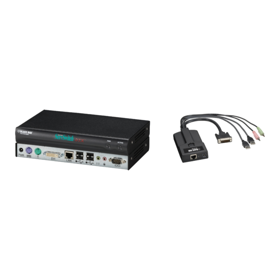
ServSwitch
Access keyboard, mouse, video, audio, and USB
mass storage devices and other USB devices
from remote workstations.
Supports virtual USB.
Includes a transmitter and a receiver.
Customer
Support
Information
DTX5000
DTX500x
™
Order toll-free in the U.S.: Call 877-877-BBOX (outside U.S. call 724-746-5500) •
FREE technical support 24 hours a day, 7 days a week: Call 724-746-5500 or fax 724-746-0746 •
Mailing address: Black Box Corporation, 1000 Park Drive, Lawrence, PA 15055-1018 •
Web site: www.blackbox.com • E-mail: info@blackbox.com
DTX5000
DTX5001
DTX5000-R DTX5001-R
DTX5000-T DTX5001-T
BLACK BOX
DTX5002
DTX5002-T
DTX5002-R
®
Advertisement
Table of Contents

Related Manuals for Black Box ServSwitch DTX5000


Summary of Contents for Black Box ServSwitch DTX5000
-
Page 1: Black Box
Order toll-free in the U.S.: Call 877-877-BBOX (outside U.S. call 724-746-5500) • Customer FREE technical support 24 hours a day, 7 days a week: Call 724-746-5500 or fax 724-746-0746 • Support Mailing address: Black Box Corporation, 1000 Park Drive, Lawrence, PA 15055-1018 • Information Web site: www.blackbox.com • E-mail: info@blackbox.com DTX5000... - Page 2 Trademarks Used in this Manual Trademarks Used in this Manual Black Box and the Double Diamond logo are registered trademarks of BB Technologies, Inc. Macintosh, Mac, and Mac OS are registered trademarks of Apple, Inc. IBM is a registered trademark of International Business Machines Corporation.
- Page 3 FCC and IC RFI Statements Federal Communications Commission and Industry Canada Radio Frequency Interference Statements This equipment generates, uses, and can radiate radio-frequency energy, and if not installed and used properly, that is, in strict accordance with the manufacturer’s instructions, may cause inter ference to radio communication. It has been tested and found to comply with the limits for a Class A computing device in accordance with the specifications in Subpart B of Part 15 of FCC rules, which are designed to provide reasonable protection against such interference when the equipment is operated in a commercial environment.
-
Page 4: Instrucciones De Seguridad
NOM Statement Instrucciones de Seguridad (Normas Oficiales Mexicanas Electrical Safety Statement) 1. Todas las instrucciones de seguridad y operación deberán ser leídas antes de que el aparato eléctrico sea operado. 2. Las instrucciones de seguridad y operación deberán ser guardadas para referencia futura. 3. -
Page 5: Table Of Contents
Advanced Operations ..............................69 Appendix A: Factory Default Settings ............................72 Appendix B: Troubleshooting ..............................73 Problems/Solutions .............................. 73 Contacting Black Box ............................76 Calling Black Box ..............................76 Appendix C: Login Error Messages ............................77 724-746-5500 | blackbox.com Page 5... -
Page 6: Specifications
Chapter 1: Specifications 1. Specifications NOTE: During the course of this product’s lifetime, modifications might be made to its hardware or firmware that could cause these specifications to change without notice. The specifications found in this version of the manual will be referencing the latest released firmware. -
Page 7: Dtx5000 Receiver
Chapter 1: Specifications Table 1-1 (continued). DTX5000-T video resolutions table. Standard timings supported Type of display 1024 x 768p at 60 Hz VESA 1024 x 768p at 70 Hz VESA 1024 x 768p at 75 Hz VESA 640 x 480p at 85 Hz VESA STD 800 x 600p at 85 Hz VESA STD... -
Page 8: Dtx5002 And Dtx5001 Transmitter
Chapter 1: Specifications Humidity Tolerance: Operating: 10 to 90% noncondensing; Storage: 5 to 95% Size: 1"H x 8.3"W x 5.1"D (2.8 x 21 x 13 cm) Weight: 1.5 lb. (0.7 kg) without packaging, cables, power supply, and manual 1.3 DTX5002 and DTX5001 Transmitter Color Depth: 24-bit Compliance: UL , FCC, cUL, VCCI, C-Tick, CE... - Page 9 Chapter 1: Specifications Table 1-2. DTX5001-T DDC table. Standard timings supported Type of display 720 x 400p at 70 Hz IBM VGA 640 x 480p at 60 Hz IBM VGA 640 x 480p at 72 Hz VESA 640 x 480p at 75 Hz VESA 800 x 600p at 60 Hz VESA...
-
Page 10: Dtx5002 And Dtx5001 Receiver
Chapter 1: Specifications Table 1-3 (continued). DTX5002-T DDC table. Standard timings supported Type of display 1280 x 960p at 60 Hz VESA STD 1680 x 1050p at 60 Hz VESA STD 1440 x 900p at 60 Hz VESA STD 1600 x 1200p at 60 Hz VESA STD 1920 x 1200p at 60 Hz VESA STD... -
Page 11: Overview
Chapter 2: Overview 2. Overview 2.1 Introduction The DTX extender system includes a transmitter and a receiver. It enables you to access keyboard, mouse, video, audio, USB mass storage devices, and other USB devices from remote workstations. The system also provides virtual USB support. NOTE: The DTX transmitters and receivers are paired as follows: •... - Page 12 Chapter 2: Overview The DTX500x transmitter provides two USB interfaces: • One port is low speed while the second video port is set to full speed. These ports are used for all keyboard and mouse peripheral devices interfacing with the target workstation, along with providing power for the DTX500x transmitter. •...
- Page 13 Chapter 2: Overview NOTE: The DTX receiver provides you with the following flexible installation features: The DTX receiver can be desk mounted or mounted on the back of a monitor; Installation requires no new drivers or software. Standard UTP cabling makes installation simple and keeps costs low.
- Page 14 Chapter 2: Overview Figure 2-1. DTX Workstation Extension System—Desktop Mode. Table 2-1. DTX workstation extension system description. Number Description DTX5000 transmitter DTX5001 transmitter Gigabit Ethernet switch DTX control appliance DTX5000 receiver Ethernet LAN DTX5001 receiver 724-746-5500 | blackbox.com Page 14 DTX5000...
-
Page 15: What's Included
Chapter 2: Overview 2.3 What’s Included Your package should include the following items. If anything is missing or damaged, contact Black Box Technical Support at 724-746-5500 or info@blackbox.com. DTX5000: DTX5001: DTX5002: • (1) Transmitter (DTX5000-T) • (1) Transmitter (DTX5001-T) • (1) Transmitter (DTX5002-T) •... -
Page 16: Dtx5000-R Back Panel
Chapter 2: Overview 2.4.2 DTX5000-R Back Panel Figure 2-3 shows the back panel of the DTX5000-R. Table 2-3 describes its components. Figure 2-3. DTX5000-R front panel. Table 2-3. DTX5000-R front-panel components. Number Component Description Barrel connector Power 6-pin mini DIN connector PS/2 keyboard 6-pin mini DIN connector PS/2 mouse... -
Page 17: Dtx5001-T Back Panel
Chapter 2: Overview 2.4.3 DTX5001-T Back Panel Figure 2-4 shows the back panel of the DTX5001-T. Table 2-4 describes its components. Figure 2-4. DTX5001-T back panel. Table 2-4. DTX5001-T back panel components. Number Component Description Barrel connector 5-VDC power CONN 1 Attach included computer cable RJ-45 connector 2.4.4 DTX5001-R Back Panel... -
Page 18: Dtx5002-T Back Panel
Chapter 2: Overview Table 2-5. DTX5001-R back-panel components. Number Component Description Barrel connector 5-VDC power 3.5-mm jack Audio DB9 connector Management (DTE serial port) RJ-45 connector DVI connector DVI or VGA video 6, 7 (2) USB Type A connectors USB peripherals 2.4.5 DTX5002-T Back Panel Figure 2-7 shows the back panel of the DTX5002-T. -
Page 19: Dtx5002-R Back Panel
WARNING: To avoid a potentially fatal shock hazard and possible damage to equipment, observe the following precautions: • Do not use a 2-wire extension cord in any Black Box product configuration. • Test AC outlets at the workstation and monitor for proper polarity and grounding. -
Page 20: Installation
• If the remote workstation is unable to supply sufficient power to support the DTX500x transmitter: an optional power supply, available from Black Box. • Mounting option: The DTX receiver mounts to the rear of a flat panel monitor via a mounting plate accessory, available from Black Box. - Page 21 Chapter 3: Installation DTX5000-T DTX5000-R Figure 3-1. DTX5000 transmitter and DTX5000 receiver point-to-point installation. To connect the transmitter: Before connecting the transmitter to the remote workstation, make sure that the resolution and the refresh rate of the remote workstation are supported by the DTX5000 receiver. Set the screen resolution and refresh rate of the remote workstation. Unsupported settings will cause blank video at the receiver.
- Page 22 Chapter 3: Installation To connect the DTX receiver: 1. Connect your keyboard, monitor, mouse, and other peripherals to the appropriately labeled ports on the back of the DTX receiver. 2. Connect the UTP cable to the RJ-45 port on the back of the DTX receiver. 3.
-
Page 23: Networked Installation
Connecting power: The DTX receiver features an external power supply. A DC power jack is located on the rear of the DTX receiver. NOTE: Use only the power supply provided by Black Box. To connect power to the DTX receiver: 1. - Page 24 Chapter 3: Installation Table 3-3. Descriptions of items in Figure 3-3. Number Description Remote workstation DTX5000 transmitter IP Network DTX5000 receiver UTP cable The DTX5000 receiver has been preconfigured with factory-default network settings. If you install only one DTX receiver and one DTX5000 transmitter on a subnet, you do not need to change these default network settings.
-
Page 25: Installing The Dtx5001 And Dtx5002 Receivers
The receiver mounts to the rear of a flat-panel monitor via a mounting plate accessory. NOTE: Mounting accessories for receivers and transmitters are ordered separately. Contact Black Box for more information. CAUTION: To reduce the risk of electric shock or damage to your equipment, disconnect the power from the DTX5002 or DTX5001 receiver by unplugging the power supply from the electrical outlet. - Page 26 Chapter 3: Installation DTX5002-T DTX5002-R Figure 3-4. Point-to-Point Installation (DTX5002 Receiver). Table 3-5. Descriptions of items in Figure 3-4. Number Description Remote Workstation DTX5002 Transmitter DTX5002 Receiver To connect the DTX5001 or DTX5002 transmitter: Before connecting the DTX5001 or DTX5002 transmitter to the remote workstation, make sure that the resolution and the refresh rate of the remote workstation are supported by the receiver.
- Page 27 Chapter 3: Installation DTX5002-T Figure 3-5. DTX5002 transmitter. Table 3-6. Descriptions of items in Figure 3-5. Number Description Video (DVI-D video supported) 3.5-mm audio NOTE: The DTX5001 transmitter features one DVI-D connector and one VGA connector. To connect the DTX5001 or DTX5002 receiver: 1.
- Page 28 The DTX5001 and DTX5002 receivers and associated transmitters feature an external power supply. A DC power jack is located on the rear. NOTE: Use only the power supply provided by Black Box. To connect power to the receiver and transmitter: 1.
-
Page 29: Networked Installation
Chapter 3: Installation 3.2.2 Networked installation The following instructions will enable you to install your receiver and transmitter in a networked configuration. In this installation, multiple transmitters and receivers are attached via the same Ethernet network. In this case, it is important for each unit to be configured with a unique IP address. - Page 30 Chapter 3: Installation NOTE: The DHCP server must be configured to assign IP addresses to the receiver that do not expire. Do not change the mode to DHCP unless the equipment is connected to a DHCP server. Table 3-9. DTX System Default Network Settings (DTX5002 Receiver). Component IP Address Type...
-
Page 31: Operation
We also require the user to have his supervisor or manager sign this document and fax it to our Black Box Technical Support. - Page 32 Chapter 4: Operation 1. Press Print Screen and select the User tab to display user information for your DTX receiver. Figure 4-1. User Dialog Box (Matrix Mode). 2. If the user has access to a list of target computers, the Target dialog box will appear when the Target tab is selected. The Target dialog box displays a list of target computers to which the user has access.
- Page 33 Chapter 4: Operation Figure 4-3. Receiver Connected to Transmitter. -or- Click the Trans radio button to view the system information for your transmitter. NOTE: If there is no transmitter connected, the Trans radio button option will display as No Target. Initiating a connection with a remote computer in Extender Mode: 1.
- Page 34 Chapter 4: Operation 1. Press Print Screen and select the Net tab to configure network parameters for your DTX receiver or transmitter. Figure 4-5. Network Config Menu (Receiver). 2. To change the receiver network configuration, select Rcvr from the Network Config menu and fill out the desired information.
- Page 35 Chapter 4: Operation Figure 4-6. Configuration Menu (OSD Timeout and Auto Logout). 2. Enter the desired amount of time for the OSD to be displayed. 3. Click “Apply” to save the changes. Setting the Auto Logout Time-out If there is no keyboard or mouse activity for an amount of time greater than the value set in the Auto Logout timeout, the receiver will automatically disconnect from the transmitter and log off from the DTX Control appliance.
-
Page 36: The Serial Menu
Chapter 4: Operation To display system information in Extender Mode: 1. Press “Print Screen.” In Extender Mode, the Info tab displays user information for your DTX receiver by default. (See Figure 4-7.) Figure 4-7. DTX Receiver Connected to Transmitter. 2. Click the Rcvr radio button to view system information for your DTX receiver. -or- Click the Trans radio button to view the system information for your transmitter. -
Page 37: Configuring Network Settings
DTX receiver. Failure to set the transmitter’s network settings first may result in the system not communicating. These units may have to be sent back to Black Box to be flash upgraded. To configure network settings for the transmitter: 1. - Page 38 Chapter 4: Operation Figure 4-8. Transmitter Main Menu. NOTE: The Reset Appliance option in the Transmitter Main Menu applies only to network settings. 4. Press 1 to select the Network Configuration option and press “Enter.” (See Figure 4-9.) Figure 4-9. Network Configuration Menu. 724-746-5500 | blackbox.com Page 38 DTX5000...
- Page 39 Chapter 4: Operation 5. Press 1 to select the Transmitter Network Config option and press “Enter.” (See Figure 4-10.) Figure 4-10. Transmitter Network Configuration Menu. 6. Press “1” to select the Transmitter IP Address option and press “Enter.” 7. Type a valid IP address and press “Enter.” 8.
- Page 40 Chapter 4: Operation Figure 4-11. Receiver Main menu. NOTE: The Network Configuration Menu is different for the Extender and Desktop modes. To access the Network Configuration Menu in Extender Mode: 1. Press “1” to select the Network Configuration option and press Enter. The Network Configuration Menu (Extender Mode) appears.
- Page 41 Chapter 4: Operation 2. Press 2 to select the Transmitter IP Config option and press “Enter.” The old Transmitter IP Address is displayed beside menu option 1 (see Figure 4-13). Figure 4-13. Transmitter Configuration menu on the DTX receiver. 3. Press 1 to select the Transmitter IP Address option and press “Enter.” Type the new IP address for the transmitter and then press “Enter.”...
- Page 42 Chapter 4: Operation Figure 4-14. Appliance Information Menu. 4. Press “Enter” to activate the serial menu. The Appliance Information Menu displays. 5. Press “1” to access the Receiver Menu. If the password option is enabled, you will be prompted for a password. 6.
- Page 43 Chapter 4: Operation To configure the network settings for the receiver: 1. Press “1” to select the Receiver Network Config option in the Network Configuration Menu (in either Extender or Desktop Mode) and press “Enter.” The screen in Figure 4-16 appears. NOTE: The Receiver Network Configuration Menu is identical in both Extender and Desktop modes.
- Page 44 Chapter 4: Operation Figure 4-17. Network Speed Menu. 10. Type “0” (zero) and press “Enter” to exit and apply changes, or to return to the Network Configuration Menu. If you made a mistake and do not wish to save the changes you made to the network settings, type “C” and press “Enter.” NOTE: Changes to network configurations are applied only after you exit the Network Configuration Menu.
- Page 45 Chapter 4: Operation Figure 4-18. DTX Control IP Configuration Menu. 8. Type a valid IP address and press “Enter.” 9. Type “0” (zero) and press “Enter” to return to the Network Configuration Menu. 10. Type “0” (zero) and press “Enter” to return to the Main Menu. - or - If you do not want to save changes made in the Management Appliance IP Configuration Menu, Type C (or cancel) and return to the Main Menu.
- Page 46 Chapter 4: Operation Figure 4-19. Receiver Main Menu. 3. Press “1” to select Network Configuration and press “Enter.” The Network Configuration Menu (see Figure 4-20) will appear. Figure 4-20. Network Configuration Menu. 4. Press “2” to select Transmitter IP Config and press “Enter.” The Transmitter IP Config menu (see Figure 4-21) will appear. The old Transmitter IP Address is displayed beside menu option 1.
-
Page 47: Authentication
Chapter 4: Operation Figure 4-21. Transmitter IP Configuration Menu on the DTX Receiver. NOTE: This screen is available only in Extender Mode. 5. Press “3” to select Detect Transmitter Address and press “Enter.” 6. Turn on the transmitter. 7. The DTX receiver will detect and save the IP address of the connected transmitter. The Transmitter IP Configuration Menu will refresh, and the current IP address of the connected Transmitter will be displayed beside menu option 1. - Page 48 We require the user to have his supervisor or manager sign this document and fax it to our Black Box Technical Support.
- Page 49 Chapter 4: Operation Authentication for the transmitter You can change the password settings for the transmitter through the serial menu using the Transmitter Security Configuration Menu. To access the Transmitter Security Configuration Menu: 1. Press “Enter” to display the serial menu. 2.
-
Page 50: Flash Upgrading Your Dtx System
4.7 Flash Upgrading your DTX System You can Flash upgrade your DTX receiver and transmitter using either XMODEM or HTTP. The DTX receiver and transmitter are upgraded separately using individual upgrade files available from Black Box. For optimum system performance, keep your firmware versions current. - Page 51 NOTE: You should Flash upgrade the transmitter before you Flash upgrade the DTX receiver. 1. Download the DTX receiver upgrade file from Black Box. 2. From the serial menu, press “1” to access the Receiver Main Menu and press “Enter.” If the password option is enabled, you will be prompted for a password.
- Page 52 To Flash upgrade your DTX receiver using HTTP: 1. Download the DTX receiver upgrade file from Black Box. 2. From the serial menu, press “1” to access the Receiver Main Menu and press “Enter.” If the password option is enabled, you will be prompted for a password.
-
Page 53: Restoring Factory Default Settings
Chapter 4: Operation 6. To initiate the file transfer, press “Enter.” The connection to the transmitter will be dropped. 7. When the transfer has completed, a message will display stating: Firmware update successful. Resetting Appliance. The connection to the transmitter will be restored. NOTE: If the DTX receiver determines that the upgrade file is invalid, the DTX receiver cancels the upgrade and maintains the previous firmware version. -
Page 54: Viewing System Information
Chapter 4: Operation 4. Press “1” and “Enter” to access the Receiver Reset menu (see Figure 4-26) to initiate the reset. A message will be displayed on the serial menu that states Resetting appliance. During reset, the connection to the transmitter is dropped. When the reset is complete, you will be automatically returned to the Appliance Selection Menu. - Page 55 Chapter 4: Operation The Receiver Appliance Information Menu screen (see Figure 4-28) contains the following information and all values are read-only: • receiver name • EID number • release version • application • boot and FPGA firmware version numbers • manufacturing part number Figure 4-28.
-
Page 56: Configuring Video Input Settings
Chapter 4: Operation 4.11 Configuring Video Input Settings DTX5000 and DTX5001 receivers can transmit either digital (DVI) or analog video (VGA) from the remote workstation to your monitor. The DTX5002 receiver can transmit DVI only from the remote workstation to your analog or digital monitor. - Page 57 Chapter 4: Operation Figure 4-30. Transmitter Target Video Menu. 4. Press “1” to select DVI Normal and press “Enter.” 5. Configure video input settings as appropriate. 6. Type “0” (zero) and press “Enter” to save your changes and exit the menu. The unit resets. Preferred monitor resolutions (EDID preferred timing) DTX5000-T and DTX5002-T transmitters can be configured to prefer certain monitor resolutions.
- Page 58 Chapter 4: Operation Figure 4-31. Advanced Video Settings Menu. 4. Enter the number that represents the port to which you want to set the EDID preferred timing, then enter “0” (zero) to Exit/ Apply Changes or enter “c” to Cancel. Figure 4-32.
-
Page 59: Configuring The Osd Hotkey Sequence
Chapter 4: Operation To access the Session Retry Menu: 1. Press “Enter” to display the serial menu. 2. Press “1” to access the Receiver Main menu and press “Enter.” If the password option is enabled, you will be prompted for a password. - Page 60 Chapter 4: Operation Figure 4-34. Receiver Console Settings Menu (Extender Mode). 3. Press “1” to access the OSD Hotkey Menu and press “Enter.” The OSD Hotkey Menu (see Figure 4-35) will appear. This menu shows you the hotkey sequences that you can choose from. Figure 4-35.
-
Page 61: Osd Inactivity Timeout
Chapter 4: Operation Table 4-2. OSD Hotkey Sequences. Hotkey Sequences Print Screen (Default) Ctrl + Ctrl (L - R) Ctrl + Ctrl (L) Ctrl + Ctrl (R) Alt + Alt (L - R) Alt + Alt (L) Alt + Alt (R) Shift + Shift (L - R) Shift + Shift (L) Shift + Shift (R) -
Page 62: Audio Performance Settings
Chapter 4: Operation 2. Press “2” to access the OSD Inactivity Timer and press “Enter.” The menu in Figure 4-37 appears. Figure 4-37. OSD Inactivity Timer Menu. 3. Press “2” to choose Inactivity Time and press “Enter.” You will be prompted to enter a time-out period in the format hours:minutes (HH:MM). - Page 63 Chapter 4: Operation Figure 4-38. Transmitter Audio Performance Menu. 4. Type the number that corresponds to the audio setting you wish to apply and press “Enter.” 5. To confirm your selection and exit the screen, type “0” (zero) and press “Enter.” The unit resets after you press “Enter.” To change the audio performance setting for the DTX receiver: 1.
- Page 64 Chapter 4: Operation 4. Type the number that corresponds to the audio setting you want to apply and press “Enter.” NOTE: If you choose off, audio support will be disabled. 5. To confirm your selection and exit the screen, type “0” (zero) and press “Enter.” The unit resets after you press Enter. Display Power-Saving Mode By accessing the DTX Control appliance, you can set and display the power-saving mode feature.
- Page 65 Chapter 4: Operation Figure 4-41. Session Auto Logout Menu. 3. To enable or disable the logout timer, enter “1” to toggle back and forth. The screen will be refreshed with the new setting. 4. Enter “2” to change the logout timer. You will be prompted to enter a timeout period in the format hours:minutes (HH:MM). The maximum time-out period you can enter is 9 hours and 59 minutes (09:59).
-
Page 66: Share Mode
Chapter 5: Share Mode 5. Share Mode Share Mode allows multiple users (up to eight receivers per transmitter) to share the audio and video of a target computer over the network and arbitrate for control of that computer. Share Mode is intended for use in either Extender Mode or Desktop Mode. - Page 67 Chapter 5: Share Mode Using Share Mode in Desktop Mode Share Mode is available to DTX receivers configured for Desktop Mode via the DTX Control software. NOTE: The following procedure assumes that the transmitter connected to the target has been configured for Share Mode. In Desktop Mode, the transmitter is configured for Share Mode by the DTX Control software.
- Page 68 Chapter 5: Share Mode Configuring To use Share Mode in Extender Mode, Share Mode must be enabled from both the transmitter’s serial menu and the receiver’s serial menu. Once a transmitter is enabled for Share Mode, multiple receivers can connect with the transmitter. To enable Share Mode on the transmitter: 1.
-
Page 69: Advanced Operation
Chapter 6: Advanced Operation 6. Advanced Operation 6.1 Simple ASCII Manager Interface The DTX extender system features a Simple ASCII Manger Interface (SAMI) that allows you to have limited control over your DTX transmitters and receivers via an ASCII-based protocol delivered via TCP. The password-protected SAMI is enabled over the serial port on your DTX extender system and operates in Extender Mode only. - Page 70 Chapter 6: Advanced Operation Table 6-1 (Continued). SAMI Parameters and Descriptions. Parameter Description Type Example gateway Default gateway of the managed device. Changing set, get set gateway gateway requires a use reset command after 192.168.13.1 the response is received to be active. resp gateway 192.168.13.1 get gateway...
- Page 71 Chapter 6: Advanced Operation Figure 6-1. SAMI Menu. To configure the following on the SAMI Menu: • To enable or disable the SAMI, select “option 1” to toggle back and forth. The screen will be refreshed with the new setting. •...
-
Page 72: Appendix A: Factory Default Settings
Appendix A: Factory Default Settings Appendix A: Factory Default Settings Table A-1. DTX System Factory Defaults. DTX5000, DTX5001, and DTX5002 Receivers Name RX_<MAC address> IP Address 192.168.13.1 Default Gateway 0.0.0.0 Netmask 255.255.255.0 OSD Hotkey Sequence Print Screen OSD Inactivity Timer 00 hours 10 minutes OSD Inactivity Checkbox Enabled... -
Page 73: Appendix B: Troubleshooting
• If the transmitter cannot draw sufficient power from the remote workstation you will need to obtain an external power supply unit for the transmitter from Black Box. If connected through a USB hub, make sure that the hub can supply enough power. - Page 74 Appendix B: Troubleshooting Problem: No mouse or keyboard operation from peripherals attached to DTX receiver. Solution: • Make sure that the mouse and keyboard cables are connected to the correct PS/2 or USB ports on the DTX receiver. • Make sure that both of the USB connectors from the transmitter are securely connected to the correct connectors on the remote workstation.
- Page 75 • If the green LED on the transmitter is on, the transmitter is drawing sufficient power. • If the transmitter cannot draw sufficient power from the remote workstation, obtain an external power supply unit for the transmitter from Black Box. • The transmitter has an internal fan. Verify that the fan is functioning.
-
Page 76: Contacting Black Box
If you determine that your DTX500x is malfunctioning, do not attempt to alter or repair the unit. It contains no user-serviceable parts. Contact Black Box Technical Support at 724-746-5500 or info@blackbox.com. Before you do, make a record of the history of the problem. -
Page 77: Appendix C: Login Error Messages
Appendix C: Login Error Messages Appendix C. Login Error Messages The following table lists error messages that may appear when using the DTX500x receiver. Table C-1. DTX Control Appliance and Receiver-Initiated Error Messages. DTX500x Receiver Login Error Messages Description Login failed User attempts to log in to the DTX Control appliance. - Page 78 Appendix C: Login Error Messages Table C-1. DTX Control Appliance and Receiver Initiated Error Messages. DTX500x Receiver Login Error Messages Description Login failed This message appears when a login attempt is made while the receiver is being Out of service upgraded.
- Page 79 About Black Box Black Box Network Services is your source for more than 118,000 networking and infrastructure products. You’ll find everything from cabinets and racks and power and surge protection products to media converters and Ethernet switches all supported by free, live 24/7 Tech support available in 30 seconds or less.
Need help?
Do you have a question about the ServSwitch DTX5000 and is the answer not in the manual?
Questions and answers