
Related Manuals for Juniper BTI7800 Series


Summary of Contents for Juniper BTI7800 Series
- Page 1 BTI7800 Series Hardware Overview and Installation Guide Modified: 2019-01-28 Copyright © 2019, Juniper Networks, Inc.
- Page 2 END USER LICENSE AGREEMENT The Juniper Networks product that is the subject of this technical documentation consists of (or is intended for use with) Juniper Networks software. Use of such software is subject to the terms and conditions of the End User License Agreement (“EULA”) posted at https://support.juniper.net/support/eula/.
-
Page 3: Table Of Contents
Chapter 1 BTI7800 Series Safety Information ........21 Optical Precautions . - Page 4 Chapter 4 Installing the BTI7800 Series Chassis ....... 75 Site Requirements ..........75 Chassis Installation Kits .
- Page 5 BTI7800 Series Modules ........
- Page 6 Chapter 6 BTI7800 Series Transceiver Specifications ......153 BTI7800 Transceivers ..........153 BTI7800 SFP+ Transceiver Optical Specifications .
- Page 7 Fiber Breakout Components ........227 Copyright © 2019, Juniper Networks, Inc.
- Page 8 BTI7800 Series Hardware Overview and Installation Guide viii Copyright © 2019, Juniper Networks, Inc.
- Page 9 Chapter 1 BTI7800 Series Safety Information ........21 Figure 1: Laser Safety Warning Label with Text .
- Page 10 BTI7800 Series Hardware Overview and Installation Guide Figure 32: Top Latch - UFM3 and UFM6 ....... . . 117 Figure 33: Top Latch - UFM4 .
- Page 11 Chapter 1 BTI7800 Series Safety Information ........21 Table 3: Timing of APSD and APR Operations .
- Page 12 BTI7800 Series Transceiver Specifications ......153 Table 55: BTI7800 Series Transceivers ....... . . 153 Table 56: SFP+ 850nm 200m Dual-Rate 10.3 and 10.5Gbps (BP3AD6SS) .
- Page 13 Table 87: BTI7800 Series Module and BIC FIT Rates and MTBF ... . . 216 Table 88: BTI7800 Series Transceiver FIT Rates and MTBF ....217 Table 89: Optical Protection Switch (OPS) FIT Rates and MTBF .
- Page 14 BTI7800 Series Hardware Overview and Installation Guide Copyright © 2019, Juniper Networks, Inc.
-
Page 15: About The Documentation
® To obtain the most current version of all Juniper Networks technical documentation, see the product documentation page on the Juniper Networks website at https://www.juniper.net/documentation/ If the information in the latest release notes differs from the information in the documentation, follow the product Release Notes. -
Page 16: Table 1: Notice Icons
BTI7800 Series Hardware Overview and Installation Guide Table 1: Notice Icons Icon Meaning Description Informational note Indicates important features or instructions. Caution Indicates a situation that might result in loss of data or hardware damage. Warning Alerts you to the risk of personal injury or death. -
Page 17: Documentation Feedback
We encourage you to provide feedback so that we can improve our documentation. You can use either of the following methods: Online feedback system—Click TechLibrary Feedback, on the lower right of any page on the Juniper Networks TechLibrary site, and do one of the following: Copyright © 2019, Juniper Networks, Inc. xvii... -
Page 18: Requesting Technical Support
7 days a week, 365 days a year. Self-Help Online Tools and Resources For quick and easy problem resolution, Juniper Networks has designed an online self-service portal called the Customer Support Center (CSC) that provides you with the following features: Find CSC offerings: https://www.juniper.net/customers/support/... -
Page 19: Creating A Service Request With Jtac
About the Documentation Join and participate in the Juniper Networks Community Forum: https://www.juniper.net/company/communities/ Create a service request online: https://myjuniper.juniper.net To verify service entitlement by product serial number, use our Serial Number Entitlement (SNE) Tool: https://entitlementsearch.juniper.net/entitlementsearch/ Creating a Service Request with JTAC You can create a service request with JTAC on the Web or by telephone. - Page 20 BTI7800 Series Hardware Overview and Installation Guide Copyright © 2019, Juniper Networks, Inc.
-
Page 21: Bti7800 Series Safety Information
Handle glass fiber with care. Glass fiber can be broken if mishandled. Protect skin from exposed glass fiber. It can penetrate the skin. The BTI7800 Series equipment should be used in a controlled access area. Limit the number of personnel who have access to the optical transmission systems. Personnel should be properly trained on laser safety and authorized, if access to laser emissions is required. -
Page 22: Laser Safety
BTI7800 Series Hardware Overview and Installation Guide of optical density sufficient to reduce the exposure levels below the appropriate maximum permissible exposure, unless it has been verified that all optical transmitters are turned off and will remain off during the installation or service operation. -
Page 23: Apsd On The 96-Channel Amplifier
Chapter 1: BTI7800 Series Safety Information Without being limited to the foregoing, a service module might undergo a warm reload in the following situations: The user issues an operator command that warm reloads the service module. The user issues an operator command that cold or warm reloads the Chassis Management Module (CMM) in a single CMM system. -
Page 24: Laser Safety: Automatic Power Reduction
BTI7800 Series Hardware Overview and Installation Guide When the far end receives the shutdown signal, the far end meets (Cond. 2) and shuts down its WDM output. Both fibers are no longer illuminated by the WDM, and the safety hazard is avoided. -
Page 25: Apr On 96-Channel Amplifier Modules
Client Out port is automatically reduced to a safe level. Safety Rating and Label All BTI7800 Series products meet the FDA requirements for a class 1 laser product with a Class 1M hazard rating: LASER RADIATION DO NOT VIEW DIRECTLY WITH OPTICAL INSTRUMENTS CLASS 1M LASER PRODUCT A caution label is located on each BTI7800 Series laser circuit pack. -
Page 26: Bti7800 Series Laser Output Ports
L4 Out B L4 Out A Critical Site Warnings and Requirements WARNING: You must observe the site and safety requirements in this section to ensure safe operations and proper performance of BTI7800 Series equipment. Copyright © 2019, Juniper Networks, Inc. -
Page 27: Table 5: Environmental Site Requirements
Chapter 1: BTI7800 Series Safety Information NOTE: Restricted Access refers to an inaccessible location that is normally inaccessible by the general public by means of any administrative or engineering control measure, but is accessible to authorized personnel who might not have laser safety training. -
Page 28: Critical Safety Warnings
WARNING: Touching electrical connectors or other exposed electrical circuitry inside the BTI7800 Series chassis or other provisioned circuit packs when they are energized can cause serious injury or death. NEBS Requirements The following table lists some important regulatory requirements for NEBS (Network Equipment-Building System) that you must follow when installing BTI7800 equipment. -
Page 29: Bti7800 Series Chassis
10-Gbps and 100-Gbps interfaces including 100-Gbps coherent DWDM. Together with its ROADM capabilities, the BTI7800 Series provides a complete end-to-end optical transport solution that can scale from 10 Gbps to nx100 Gbps and beyond. -
Page 30: Bti7814 Chassis
BTI7800 Series Hardware Overview and Installation Guide Table 6: BTI7800 Chassis Types (continued) Product Equipment Chassis Code (PEC) Description BTI7801 BT8A78CH1 1-slot chassis Supports the following service modules: UFM3 UFM4 UFM6 WPS4 AMP1 NOTE: The collective name, BTI7800, is used to refer to all chassis types when distinction between chassis types is not needed. -
Page 31: Bti7800 Series Chassis
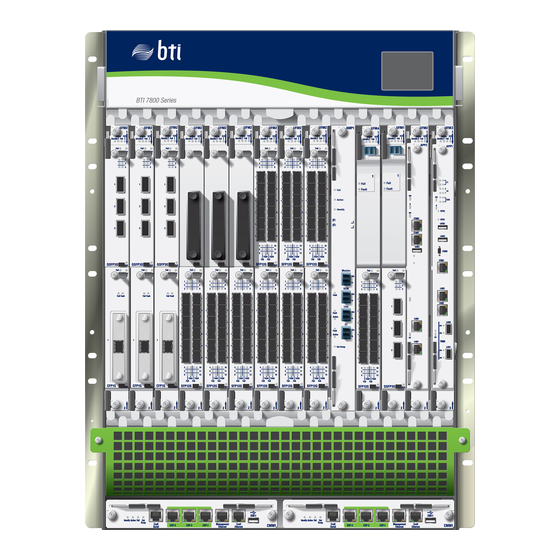
Chapter 2: BTI7800 Series Chassis Figure 3: BTI7814 Chassis Front View Figure 4: BTI7814 Chassis Rear View with 14-Slot Chassis DC Power Entry Modules Copyright © 2019, Juniper Networks, Inc. -
Page 32: Bti7814 Chassis Kits
BTI7800 Series Hardware Overview and Installation Guide Table 8: BTI7814 Major Common Equipment Components Component Release Introduced 14-Slot Chassis Alarm Panel BT8A78CAP1 Release 1.1 14-Slot Chassis Front Cooling Module BT8A78FAN3 Release 1.1 BTI7814 Booster Fan BT8A78FAN9 Release 4.1 14-Slot Chassis DC Power Entry Module BT8A78PEM3-DC Release 1.1... -
Page 33: Bti7814 Chassis Specifications
Chapter 2: BTI7800 Series Chassis Table 9: BTI7814 Kits (continued) Main Equipment Included Quantity Component PEC BTI7814 Booster Fan (FAN9) BT8A78FAN9 14-Slot Chassis, AC-KIT2 (BT8A78CH14-KIT2-AC) 14-Slot Chassis, AC BT8A78CH14-AC AC PEM BT8A78ACM1 14-Slot Chassis, AC-KIT3 (BT8A78CH14-KIT3-AC) 14-Slot Chassis, AC BT8A78CH14-AC... -
Page 34: Bti7802 Chassis
BTI7800 Series Hardware Overview and Installation Guide Table 10: BTI7814 Chassis Specifications (continued) Shell Specification NEBS GR-1089 GR-3160 (basic temperature range) BTI7802 Chassis The BTI7802 chassis has 2 universal slots that can be individually equipped with traffic-carrying service modules. The BTI7802 can be installed into 19-inch, 23-inch, and ETSI 600-mm racks. -
Page 35: Bti7802 Chassis Kits
Chapter 2: BTI7800 Series Chassis Table 11: BTI7802 Common Equipment Components (continued) Component Release Introduced Chassis Management Module (CMM) BT8A78CMM1 Release 1.1 BTI7802 Chassis Kits The BTI7802 can be ordered as a kit that includes the bare chassis along with common equipment modules, tools, and installation hardware. -
Page 36: Bti7802 Chassis Specifications
BTI7800 Series Hardware Overview and Installation Guide Table 12: BTI7802 Kits (continued) Main Equipment Included Quantity Component PEC 1-Slot/2-Slot Chassis AC Power Entry Module (AC PEM) BT8A78PEM1-AC Chassis Management Module (CMM) BT8A78CMM1 The following BTI7802 equipment changes were introduced in Release 1.6:... -
Page 37: Bti7801 Chassis
Chapter 2: BTI7800 Series Chassis Table 13: BTI7802 Chassis Specifications (continued) Shell Specification Weight (unpopulated chassis) 15 lb 6.80 kg Total chassis power (fully populated) 1000 W NEBS GR-1089 GR-3160 BTI7801 Chassis The BTI7801 is a 1-slot chassis designed to extend BTI7800 reach to smaller sites that require point-to-point connectivity. -
Page 38: Bti7801 Chassis Kits
BTI7800 Series Hardware Overview and Installation Guide Figure 7: BTI7801 Chassis Rear View To provide front access to management ports and chassis alarm indicators, the BTI7801 cooling module is fitted with management ports and chassis status LEDs. For the management ports to be operational, the 1-Slot Chassis Front Cooling Module (FAN5) must be deployed with the optional Ethernet and Serial Link (ESL) module. -
Page 39: Bti7801 Chassis Specifications
Chapter 2: BTI7800 Series Chassis Table 15: BTI7801 Kits (continued) Main Equipment Included Quantity Component PEC 1-slot chassis BT8A78CH1 Chassis Management Module (CMM) BT8A78CMM1 1-Slot Chassis Front Cooling Module (FAN5) BT8A78FAN5 Chassis Common Tool Kit BT8A78TOOLS 1-slot Chassis, DC-KIT1 (BT8A78CH1-KIT1-DC) -
Page 40: Bti7814 Power
BTI7800 Series Hardware Overview and Installation Guide BTI7801 Power on page 52 BTI7800 Series Component Power Consumption on page 53 BTI7814 Power The BTI7814 is powered by field-replaceable Power Entry Modules. Both AC and DC versions are supported. NOTE: If your chassis has redundant PEMs, you will be able to replace a failed PEM while the redundant PEM continues to power the chassis. -
Page 41: Bti7814 Dc Pem
Chapter 2: BTI7800 Series Chassis Table 17: BTI7814 Backplane DC Power Distribution Input Feeds Channel Slot Modules A1 and B1 Service module slots 3 Service Modules and 4 Service module slots 5 Service Modules and 6 Service module slots 7... -
Page 42: Figure 8: Bti7814 14-Slot Chassis Dc Power Entry Module
BTI7800 Series Hardware Overview and Installation Guide Each DC PEM features two dual-stud return terminals and two dual-stud feed terminals. Typically, only one dual-stud terminal is used. The extra dual-stud terminals can be used for particular applications, such as laboratory applications. -
Page 43: Bti7814 Dc Pem Specifications
4800 W Power Capacity Voltage Input Range -42 VDC to -60 VDC 125 A External Breaker The power cord is not supplied by Juniper Networks. Power Cable Size 2 AWG Receptacle Not applicable Plug Not applicable Copyright © 2019, Juniper Networks, Inc. -
Page 44: Bti7814 Ac Pem
Reverse Normal operation. voltage The wiring is reversed. Before using for planning or implementation purposes, contact Juniper Networks Support to confirm the power consumption values. Input voltages outside this range might cause the chassis to operate unpredictably. NOTE: The REV LED indicates red to alert the installer that the chassis has been wired in reverse polarity. -
Page 45: Figure 9: Bti7814 Ac Pem Housing
Chapter 2: BTI7800 Series Chassis The AC PEM rectifier housing (Figure 9 on page 45) is 4RU tall, and can contain up to four AC PEMs. The rectifier housing and rectifiers come pre-installed on the chassis when you order the chassis with the AC option. -
Page 46: Bti7814 Ac Pem Specifications
BTI7800 Series Hardware Overview and Installation Guide Internally, the DC outputs of these rectifiers are protected through user-replaceable fuses. The fuse array for the A1/A2 feeds is located behind the rectifier in Slot 2. The fuse array for the B1/B2 feeds is located behind the rectifier in Slot 3. For instructions on replacing these fuses, see “Replacing the Fuses on a BTI7814 AC PEM”... - Page 47 AC PEMs. External Breaker 20 A Power Cable The power cord is not supplied by Juniper Networks. NOTE: The power cord must be installed by a qualified electrician. The cord set must be certified to the following CSA/UL standards: CSA C22.2 No.
-
Page 48: Bti7802 Power
Table 19: BTI7814 AC Power Entry Module (BT8A78ACM1) Specifications (continued) Item Specification Before using for planning or implementation purposes, contact Juniper Networks Support to confirm the power consumption values. Running with input voltages below 180 VAC lowers the AC PEM power capacity. See the row above. -
Page 49: Bti7802 Dc Pem Specifications
Chapter 2: BTI7800 Series Chassis Figure 11: BTI7802 1-Slot/2-Slot Chassis DC Power Entry Module If a seated DC PEM is not connected to a power feed, but the chassis is otherwise powered (by the other PEM), the following occurs: The unpowered DC PEM is shown in inventory. -
Page 50: Bti7802 Ac Pem
BTI7800 Series Hardware Overview and Installation Guide Table 20: BTI7802 1-Slot/2-Slot Chassis DC Power Entry Module (BT8A78PEM1-DC) Specifications (continued) Item Specification -42 V DC to -60 V DC Voltage Input Range NOTE: Input voltages outside this range might cause the chassis to operate unpredictably. -
Page 51: Bti7802 Ac Pem Specifications
Chapter 2: BTI7800 Series Chassis Figure 12: BTI7802 1-Slot/2-Slot Chassis AC Power Entry Module If a seated AC PEM is not connected to a power feed, but the chassis is otherwise powered (by another PEM), the following occurs: The unpowered AC PEM is not shown in inventory. -
Page 52: Bti7801 Power
BTI7800 Series Hardware Overview and Installation Guide Table 21: BTI7802 1-Slot/2-Slot Chassis AC Power Entry Module (BT8A78PEM1-AC) Specifications (continued) Item Specification External Breaker The power cord can be ordered from Juniper Networks. Power Cable Size 18AWG (recommended for input voltages below 180VAC) Receptacle (to chassis) -
Page 53: Bti7800 Series Component Power Consumption
Chapter 2: BTI7800 Series Chassis BTI7800 Series Component Power Consumption NOTE: Before using for planning or implementation purposes, contact Juniper Networks Support to confirm the power consumption values. Table 22: BTI7800 Series Component Power Consumption (at 40°C) Module Typical (W) Maximum (W) Service Modules... - Page 54 BTI7800 Series Hardware Overview and Installation Guide Table 22: BTI7800 Series Component Power Consumption (at 40°C) (continued) Module Typical (W) Maximum (W) BTI7814 Chassis Alarm Panel (CAP1) BT8A78CAP1 BTI7802 Chassis Alarm Panel (CAP2) BT8A78CAP2 BTI7814 14-Slot Chassis DC Power Entry BT8A78PEM3-DC 99.9% efficient...
-
Page 55: Cooling
Chapter 2: BTI7800 Series Chassis Table 22: BTI7800 Series Component Power Consumption (at 40°C) (continued) Module Typical (W) Maximum (W) QSFP28 100GE LR4 QSFP-100G-LR4-2 – (740-074685) QSFP28 100GE Ethernet/OTN LR4 QSFP-100G-LR4-D – (740-073859) QSFP28 100GE SR4 QSFP-100GBASE-SR4 – (740-058734) CFP 100GBASE-SR10 100m... -
Page 56: Bti7814 Fan3 Specifications
BTI7800 Series Hardware Overview and Installation Guide Figure 13: BTI7814 Cooling System Air Flow Continuous System Operation During a Fan Failure The BTI7814 continues to operate when a cooling module fails, as follows: The system is capable of cooling up to 350 Watts per slot with a single cooling module failure at 35°C indefinitely. -
Page 57: Bti7814 Booster Fans
Either a FAN3 module or the other FAN9 module is not present in the chassis. There is no active CMM in the system. The system software and firmware have not yet been upgraded to BTI7800 Series Release 4.1 or later. -
Page 58: Bti7814 Booster Fan Specifications
BTI7800 Series Hardware Overview and Installation Guide BTI7814 Booster Fan Specifications Table 24: FAN9 Specifications Item Specification Physical Dimensions Width 8 in 203.2 mm Height 3.5 in 88.9 mm Depth 6 in 152.4 mm Weight 2 lb 0.9 kg Maximum: 125 W Power Consumption (40°C ambient) -
Page 59: Figure 15: 2-Slot Chassis Cooling Module (Bt8A78Fan2) Right And Left Side
Chapter 2: BTI7800 Series Chassis Figure 15: 2-Slot Chassis Cooling Module (BT8A78FAN2) Right and Left Side Views NOTE: The front, rear, and both sides of the chassis must remain unobstructed to ensure adequate air flow and prevent overheating. The BTI7802 chassis (BT8A78CH2-I02) uses the 2-Slot Chassis Cooling Module (BT8A78FAN2) to create a side-to-side, right-to-left air flow. -
Page 60: Bti7802 Fan2 Specifications
BTI7800 Series Hardware Overview and Installation Guide Figure 17: BTI7802 Cooling System with Rear Exhaust Adapter NOTE: The cooling system air filter is accessible from the rear of the chassis. The BT8A78CH2-I02 chassis is shipped with the air filter installed. -
Page 61: Figure 18: 1-Slot Chassis Front Cooling Module (Bt8A78Fan5)
Chapter 2: BTI7800 Series Chassis Figure 18: 1-Slot Chassis Front Cooling Module (BT8A78FAN5) Figure 19 on page 62 shows the airflow through the chassis. Outside air enters the chassis through the air intake above the service module slot. The fans draw the air into the fan module slot and blow the air along the ESL module slot towards the main chassis air exhaust at the rear. -
Page 62: Bti7801 Fan5 Specifications
BTI7800 Series Hardware Overview and Installation Guide Figure 19: BTI7801 Airflow NOTE: The front and rear of the chassis must remain unobstructed to ensure adequate airflow and prevent overheating. BTI7801 FAN5 Specifications Table 26: 1-Slot Chassis Front Cooling Module (BT8A78FAN5) Specifications... -
Page 63: Bti7801 Fan5 Management Ports And The Esl Module
Chapter 2: BTI7800 Series Chassis Table 26: 1-Slot Chassis Front Cooling Module (BT8A78FAN5) Specifications (continued) Item Specification Typical: 65 W Power Consumption (40°C ambient) NOTE: Before using for planning or implementation Maximum: 72 W purposes, contact Juniper Networks Support to confirm the power consumption values. -
Page 64: Bti7801 Esl Specifications
BTI7800 Series Hardware Overview and Installation Guide Figure 20: Ethernet and Serial Link Module (BT8A78ESL1) NOTE: The FAN5 management and craft ports are only operational if the optional ESL module is installed and connected to the CMM. BTI7801 ESL Specifications... -
Page 65: Chassis Alarm Panel (Cap)
Chapter 2: BTI7800 Series Chassis Table 27: Ethernet and Serial Link (BT8A78ESL1) Specifications (continued) Item Specification Link (right): Green when the link is up on the corresponding CMM Port LEDs management port. Activity (left): Not used. This LED is green when the Link LED is lit. -
Page 66: Bti7814 Cap1 Specifications
BTI7800 Series Hardware Overview and Installation Guide BTI7814 CAP1 Specifications Table 28: 14-Slot Chassis Alarm Panel (BT8A78CAP1) Specifications Item Specification Physical Dimensions Width 3.00 in 76.2 mm Height 1.25 in 31.8 mm Depth 4.50 in 114.3 mm Weight 0.5 lbs 0.22 kg... -
Page 67: Bti7802 Cap2 Specifications
Chapter 2: BTI7800 Series Chassis Figure 22: BTI7802 Chassis Alarm Panel BTI7802 CAP2 Specifications Table 29: 2-Slot Chassis Alarm Panel (BT8A78CAP2) Specifications Item Specification Physical Dimensions Width 3.00 in 76.2 mm Height 1.25 in 31.8 mm Depth 4.50 in 114.3 mm Weight 1.5 lbs... - Page 68 BTI7800 Series Hardware Overview and Installation Guide Copyright © 2019, Juniper Networks, Inc.
-
Page 69: Chapter 3 Unpacking The Bti7800 Series Shipment
If the packaging is damaged and possible equipment damage is present, preserve as much of the packaging as possible and contact Juniper Networks Support. Open the top of the shipping container. Remove any information sheets and sub-packages. -
Page 70: Verify Shipment Contents
BTI7800 Series Hardware Overview and Installation Guide With the chassis still on the pallet, remove the plastic strapping from the box and lift the box up, over and away from the chassis. Place the box out of the way, so that it is not obstructing the area around the chassis, or obstructing the path to the chassis rack. -
Page 71: Figure 23: Chassis Installation Kit
Chapter 3: Unpacking the BTI7800 Series Shipment Figure 23: Chassis Installation Kit To prevent bodily injury when lifting or moving the chassis or other components, follow these guidelines. Considerations Before You Begin The weight of the chassis, as delivered, is approximately 80 lb (36.30 kg), which includes the Power Entry Modules (PEMs) and FAN modules. -
Page 72: Mounting The Support Frame
BTI7800 Series Hardware Overview and Installation Guide When lifting the chassis, bend at your knees not your waist. When moving the chassis, be sure you have an unobstructed path to the rack. Mounting the Support Frame The support frame is used, temporarily, to support the chassis during chassis rack installation. - Page 73 Chapter 3: Unpacking the BTI7800 Series Shipment NOTE: For detailed rack mounting procedures, refer to “Rack-Mounting the BTI7814 Chassis” on page Copyright © 2019, Juniper Networks, Inc.
- Page 74 BTI7800 Series Hardware Overview and Installation Guide Copyright © 2019, Juniper Networks, Inc.
-
Page 75: Chapter 4 Installing The Bti7800 Series Chassis
Site Requirements WARNING: You must observe these site and safety requirements to ensure safe operations and proper performance of BTI7800 Series equipment. NOTE: Restricted Access refers to an inaccessible location that is normally inaccessible by the general public by means of any administrative or engineering control measure, but is accessible to authorized personnel who might not have laser safety training. -
Page 76: Chassis Installation Kits
Storage temperature Chassis Installation Kits Each BTI7800 Series chassis is shipped with one or more installation kits that include the hardware needed to mount, power, and ground the chassis. The BTI7800 Series Chassis Common Tool Kit (BT8A78TOOLS) includes BIC extractor... -
Page 77: Table 32: Bti7814 Chassis Crimp Lug Installation Kit (Bt8A7867)
Chapter 4: Installing the BTI7800 Series Chassis Table 31: Chassis Installation Kit (BT8A7865) (continued) Main Components Quantity Function Screw M6 X 12 mm, Hex head steel BTI7814 ground lugs to chassis. Screw, M4 X 6 mm, Pan head, Phillips, with Ext lock BTI7802 ground lugs to chassis. -
Page 78: Tools For Installation
BTI7801 chassis into a 4-post 19-inch or ETSI 600-mm cabinet. Tools for Installation Tools to have on-hand when you are ready to install the BTI7800 Series chassis: Number 1 Phillips screwdriver Number 2 Phillips screwdriver 10 mm socket or wrench ®... - Page 79 Chapter 4: Installing the BTI7800 Series Chassis Ensure the 19-inch mounting brackets are removed and the 23-inch mounting brackets are securely attached to the chassis. WARNING: This equipment is intended to be installed and serviced by qualified personnel. Make sure you are familiar with the site and safety guidelines.
-
Page 80: Figure 26: Rear Exhaust Adapter Kit (Bt8A78Rex)
BTI7800 Series Hardware Overview and Installation Guide Figure 26: Rear Exhaust Adapter Kit (BT8A78REX) Item Bracket Description Fastener Right rear air deflector (open front, 2 captive screws fasten to chassis closed rear) 2 M3.5x5mm screws (supplied) fasten to 23 inch bracket... - Page 81 Chapter 4: Installing the BTI7800 Series Chassis Install the right rear air deflector. a. Place the air deflector behind the 23-inch mounting bracket. b. Insert the metal tab into the slot of the 23-inch mounting bracket. c. Align the bracket drill holes with the mounting bracket screw inserts. Fasten the bracket to the mounting bracket using the two M3.5 screws.
- Page 82 BTI7800 Series Hardware Overview and Installation Guide a. Place the air deflector behind the 23-inch mounting bracket. b. Insert the metal tab into the slot of the 23-inch mounting bracket. c. Align the bracket drill holes with the mounting bracket screw inserts. Fasten the bracket to the mounting bracket using the two M3.5 screws.
- Page 83 Chapter 4: Installing the BTI7800 Series Chassis a. Place the cover in front of the 23-inch mounting bracket. b. Insert the metal tab into the slot of the 23-inch mounting bracket. c. Align the captive screws on the bracket to the chassis screw inserts. Fasten the captive screws.
-
Page 84: Rack-Mounting The Chassis
BTI7800 Series Hardware Overview and Installation Guide Rack-Mounting the Chassis CAUTION: Before you proceed, ensure that you are familiar with the safety information described in the BTI7800 Series Hardware Overview and Installation Guide. NOTE: Be familiar with the electrical and occupational safety guidelines for... - Page 85 Chapter 4: Installing the BTI7800 Series Chassis Number 1 and Number 2 Phillips screwdrivers 10 mm socket wrench ® T15 Torx screwdriver (for fastening mounting brackets onto the chassis) Chassis Installation Kit (BT8A7865) 14-Slot Chassis Shelf Installation Support Bracket Kit (BT8A78SSB1) - optional...
-
Page 86: Rack-Mounting The Bti7802 Chassis
BTI7800 Series Hardware Overview and Installation Guide Rack-Mounting the BTI7802 Chassis Table 35: Rack-Mounting Considerations Issue Description Rack size ANSI 19 in ETSI 600 mm ANSI 23 in Cabinet size ETSI 600 mm x 600 mm NEBS 24 in (depth) -
Page 87: Rack-Mounting The Bti7801 Chassis
Chapter 4: Installing the BTI7800 Series Chassis For balance, two people are needed if the chassis is not being seated on a rack shelf. One person should be positioned at the center front of the chassis and the other at the center back. - Page 88 BTI7800 Series Hardware Overview and Installation Guide Place the BTI7801 on a flat surface with the front facing you. Install the correct mounting brackets for the desired rack width. Mounting brackets for 19-inch, 600-mm, and 23-inch racks are supplied. Get into rack-mounting position. Choose one of the following options: One person is needed if the chassis is being seated on a rack shelf.
-
Page 89: Grounding The Chassis
Chapter 4: Installing the BTI7800 Series Chassis If you are mounting multiple BTI7801 chassis, one on top of the other, only the bottom BTI7801 chassis requires the support bracket. The support bracket should not be used if you are mounting the BTI7801 directly on top of other equipment. -
Page 90: Frame-Grounding A Bti7802 Chassis
BTI7800 Series Hardware Overview and Installation Guide Location of Ground Connections There are two grounding locations on the rear of the chassis, one on each bottom corner beneath the PEMs. Procedure To frame ground the chassis, use the following procedure: Use a wire stripper tool to strip the end of the ground wire to the correct length (5.0... - Page 91 Chapter 4: Installing the BTI7800 Series Chassis NOTE: NEBS Compliance Statements for GR-1089: Only copper cables are to be used for grounding purposes. The grounding conductor AWG size should match the size of the power cable AWG. Bare conductors must be coated with antioxidant before crimp connections are made.
-
Page 92: Frame-Grounding A Bti7801 Chassis
BTI7800 Series Hardware Overview and Installation Guide Check the connectivity of the grounding by using a multimeter to measure the resistance between the shelf and the frame. Put one test lead in contact with an unpainted zone of the chassis and the other test lead in contact with the equipment frame. - Page 93 Chapter 4: Installing the BTI7800 Series Chassis Installation Tools and Kits Number 1 and Number 2 Phillips screwdrivers Wire stripping and crimping tool Multimeter Chassis Installation Kit (BT8A7865) A grounding cable that is at least the same size as the power cable. The single stud lugs supplied in the Chassis Installation Kit are for use with 10-12 AWG cables.
-
Page 94: Powering The Chassis
BTI7800 Series Hardware Overview and Installation Guide Check the connectivity of the grounding by using a multimeter to measure the resistance between the shelf and the frame. Put one test lead in contact with an unpainted zone of the chassis and the other test lead in contact with the equipment frame. - Page 95 To avoid personal injury or damage to chassis components, ensure there is no power going to the chassis. Make sure you are familiar with the site and safety guidelines described in the BTI7800 Series Hardware Overview and Installation Guide. WARNING: Before you proceed: Do not work alone.
-
Page 96: Figure 27: Dc Pem Power Feed Connections
BTI7800 Series Hardware Overview and Installation Guide Multimeter Chassis Installation Kit (BT8A7865) Chassis Crimp Lug Installation Kit (BT8A7867). The dual stud lugs supplied in the Chassis Crimp Lug Installation Kit are for use with 2 AWG cables. The 2 AWG lugs can crimp down to 4 AWG. -
Page 97: Connecting The Ac Power Feeds To A Bti7814 Ac Pem
To avoid personal injury or damage to chassis components, ensure there is no power going to the chassis. Make sure you are familiar with the site and safety guidelines described in the BTI7800 Series Hardware Overview and Installation Guide. Copyright © 2019, Juniper Networks, Inc. - Page 98 BTI7800 Series Hardware Overview and Installation Guide WARNING: Before you proceed: Do not work alone. The chassis must be grounded to the frame in which it is mounted. The power source to which you are connecting the chassis must be powered off.
- Page 99 Chapter 4: Installing the BTI7800 Series Chassis Copyright © 2019, Juniper Networks, Inc.
-
Page 100: Powering The Bti7802 Chassis
BTI7800 Series Hardware Overview and Installation Guide b. Attach the AC power cables to the respective clips. Follow the appropriate steps to connect the other end of the cables to the power source in your plant. Ensure the power source to which you are connecting the cables is powered off. -
Page 101: Installing And Cabling The Bti7802 Dc Pem
To avoid personal injury or damage to chassis components, ensure there is no power going to the chassis. Make sure you are familiar with the site and safety guidelines described in the BTI7800 Series Hardware Overview and Installation Guide. WARNING: Before you proceed: Do not work alone. -
Page 102: Table 37: Bti7802 Dc Power Cable Assembly (Bt8A78Pwr1)
BTI7800 Series Hardware Overview and Installation Guide Multimeter DC Power Cable Assembly (BT8A78PWR1) Table 37: BTI7802 DC Power Cable Assembly (BT8A78PWR1) DC PEM Cable Connector DC PEM Cable Procedure Verify there is no power going to the chassis. Verify the chassis is properly grounded. For information on frame-grounding the chassis, refer to “Frame-Grounding a BTI7802 Chassis”... -
Page 103: Installing And Cabling The Bti7802 Ac Pem
To avoid personal injury or damage to chassis components, ensure there is no power going to the chassis. Make sure you are familiar with the site and safety guidelines described in the BTI7800 Series Hardware Overview and Installation Guide. WARNING: Before you proceed: Do not work alone. - Page 104 BTI7800 Series Hardware Overview and Installation Guide The circuit breaker switch, to which the power source is wired, must be shut off. Locate the emergency power-off switch for the location in which you are working. Do not overload the power source to which you are connecting the chassis.
-
Page 105: Powering The Bti7801 Chassis
Chapter 4: Installing the BTI7800 Series Chassis The AC PEM LEDs start to light up. The AC OK light turns solid green when the module is ready. Perform a voltage checklist. The voltage can be checked only at the breaker/fuse panel end where the AC power cable is terminated. -
Page 106: Bti7802 Esd Jack Location
BTI7800 Series Hardware Overview and Installation Guide BTI7802 ESD Jack Location There is one ESD jack on the BTI7802 chassis: At the front of the chassis, between the lower Chassis Management Module slot and the Power Entry Module BTI7801 ESD Jack Location There is one ESD jack on the BTI7801 chassis: At the front of the chassis, top right corner above the cable guide. -
Page 107: Bti7800 Series Modules
The following table lists the management and traffic modules for the BTI7800. Traffic modules refer to all modules that carry user traffic, and include service modules, BTI Interface Cards, and passive rack-mounted modules. Table 38: BTI7800 Series Management and Traffic Modules Module Description... -
Page 108: Module Installation And Removal Guidelines
BTI7800 Series Hardware Overview and Installation Guide Table 38: BTI7800 Series Management and Traffic Modules (continued) Module Description Introduced 96-Channel Amplifier (AMP1) Provides DWDM composite signal BT8A78AMP1 Release 1.1 amplification in point-to-point applications. NOTE: This module is not supported on the BTI7801. - Page 109 Safety Warnings This equipment is intended to be installed and serviced by qualified personnel. Be familiar with the safety guidelines described in the BTI7800 Series Hardware Overview and Installation Guide. Ensure the chassis is installed properly and secured onto the rack.
-
Page 110: Chassis Management Module (Cmm)
BTI7800 Series Hardware Overview and Installation Guide If you need to set a module down, place it back into its antistatic packaging or on a properly-grounded antistatic mat. Handle the module by its edges and/or its faceplate and avoid touching any pins, leads, or solder connections on the circuit board. -
Page 111: Cmm1 Specifications
Chapter 5: BTI7800 Series Modules Figure 29: CMM Slot Locations on BTI7814 Figure 30: CMM Slot Locations on BTI7802 Figure 31: CMM Slot Location on BTI7801 (Rear View) CMM1 Specifications Table 40: Chassis Management Module 1 (BT8A78CMM1) Specifications Item Specification... - Page 112 BTI7800 Series Hardware Overview and Installation Guide Table 40: Chassis Management Module 1 (BT8A78CMM1) Specifications (continued) Item Specification Typical: 70 W Power Consumption (40°C ambient) NOTE: Before using for planning or implementation Maximum: 77 W purposes, contact Juniper Networks Support to confirm the power consumption values.
-
Page 113: Cmm1 Latches
Chapter 5: BTI7800 Series Modules CMM1 Latches The CMM latches have a spring-loaded locking mechanism. The latches must be fully closed and locked for proper module operation. Installing a CMM Use this procedure to install a CMM. It is recommended that you install two CMMs for redundancy. -
Page 114: Removing A Cmm
BTI7800 Series Hardware Overview and Installation Guide e. Press firmly on a part of the faceplate away from the latches. The latches close by themselves as the module is seated. Take care not to pinch your fingers as the latches close. -
Page 115: Universal Forwarding Module (Ufm)
Chapter 5: BTI7800 Series Modules Universal Forwarding Module (UFM) The Universal Forwarding Module (UFM) is a transport service module that performs functions such as transponding and muxponding. UFMs are available in different types from fixed to highly flexible configurations. Table 41: UFM Types... -
Page 116: Ufm Specifications
BTI7800 Series Hardware Overview and Installation Guide Installing a UFM on page 117 Removing a UFM on page 119 Replacing a UFM4 with a UFM3 on page 120 UFM6 Installation Rules on page 121 UFM Specifications Table 42: UFM Specifications... -
Page 117: Installing A Ufm
Chapter 5: BTI7800 Series Modules Figure 32: Top Latch - UFM3 and UFM6 Figure 33: Top Latch - UFM4 NOTE: The design of the UFM4 top latch accommodates the space taken up by the integrated MSA transceiver. The bottom latch on all UFMs (“UFM Latches”... - Page 118 BTI7800 Series Hardware Overview and Installation Guide If you have pre-provisioned the module, ensure the module is administratively enabled. If the module is not administratively enabled, the module will not be acknowledged by the CMM. For information on how to enable the module, see the BTI7800 Software Configuration Guide.
-
Page 119: Removing A Ufm
Chapter 5: BTI7800 Series Modules e. Close the latches by moving both latches to the inward position and push in until they fully close. The latches are angled slightly outward from the faceplate when fully engaged. f. Retract the black handles to allow clearance for the BIC modules, as applicable. -
Page 120: Replacing A Ufm4 With A Ufm3
Use this procedure to replace a UFM4 with a UFM3. Prerequisites: The UFMs must be similarly equipped. See the BTI7800 Series Software Configuration Guide for the qualifying criteria. This procedure describes a very specific type of UFM replacement where a UFM with an integrated 100G Coherent MSA XCVR is replaced by a UFM with a 1x CFP BIC and a 100G Coherent CFP. -
Page 121: Ufm6 Installation Rules
Chapter 5: BTI7800 Series Modules NOTE: Be familiar with the site, safety, and installation guidelines described “Module Installation and Removal Guidelines” on page 108. Mark all fibers that you plan to disconnect from the UFM4 and reconnect to the UFM3. -
Page 122: Bti Interface Card (Bic)
BTI7800 Series Hardware Overview and Installation Guide NOTE: Failure to comply with these rules might lead to adverse thermal behavior and premature failure. BTI Interface Card (BIC) BTI Interface Cards (BICs) are modules that hold pluggable transceivers. The transceivers are plugged into the BICs, which in turn are inserted into the UFMs. A BIC can be installed into a UFM3 or a UFM4. -
Page 123: Figure 35: 12X Sfp+ Bti Interface Card
Chapter 5: BTI7800 Series Modules Figure 35: 12x SFP+ BTI Interface Card Table 44: 12x SFP+ BIC (BT8A78SFP12G) Specifications Item Specification Physical Dimensions Width 1.1 in 29.0 mm Height 5.9 in 150.0 mm Depth 6.4 in 163.0 mm Weight 1.0 lb 0.45 kg... -
Page 124: Cfp Bic
BTI7800 Series Hardware Overview and Installation Guide Table 44: 12x SFP+ BIC (BT8A78SFP12G) Specifications (continued) Item Specification OTN OTU2, 10.709Gbps Supported Forward Error Correction Modes (FEC) RS FEC per G.975 I.4 FEC per G.975.1 I.7 FEC per G.975.1 SFP+ (12) -
Page 125: Bic Handles And Latches
Chapter 5: BTI7800 Series Modules Table 45: 1x CFP BIC (BT8A78CFP1G) Specifications (continued) Item Specification Weight 1.0 lb 0.45 kg Power Consumption (40°C ambient) Typical: 32W NOTE: Before using for planning or implementation Maximum: 38W purposes, contact Juniper Networks Support to confirm the power consumption values. -
Page 126: Removing A Bic
BTI7800 Series Hardware Overview and Installation Guide You should install the BIC into a UFM that is already installed in a chassis. An installed UFM provides stability as you slide the BIC into the BIC slot. Otherwise you run the risk of damaging components on the BIC if there is movement when sliding it into the BIC slot. -
Page 127: Figure 37: Bic Extractor Tool
Chapter 5: BTI7800 Series Modules You should remove the BIC from the UFM while the UFM is installed in the chassis. An installed UFM provides stability as you slide the BIC out of the BIC slot. Otherwise you run the risk of damaging components on the BIC if there is movement when sliding it out of the BIC slot. -
Page 128: Replacing A Bic
BTI7800 Series Hardware Overview and Installation Guide NOTE: The BIC can also be placed in hot-swap mode if the BIC is administratively disabled, or if the containing UFM is administratively disabled. Loosen the BIC faceplate thumbscrew, located at the top of the BIC. Use a screwdriver if necessary. -
Page 129: Figure 38: Bic Filler Panel
Chapter 5: BTI7800 Series Modules Figure 38: BIC Filler Panel NOTE: Be familiar with the site, safety, and installation guidelines described “Module Installation and Removal Guidelines” on page 108. Locate the UFM in which you want to install the BIC filler panel and move aside any fibers blocking access. -
Page 130: Bic Leds
BTI7800 Series Hardware Overview and Installation Guide BIC LEDs Table 46: BIC LEDs LEDs Color Description Active Green The module is operating normally. Fail The module has failed. H/S (Hot Swap) Blue ON: The module is in a quiescent state, and can be removed from the slot after a minimum of 5 seconds in this state. -
Page 131: Amp1 Specifications
Chapter 5: BTI7800 Series Modules Figure 39: 96-Channel Amplifier Module AMP1 Specifications on page 131 AMP1 Latches on page 133 Installing an AMP1 Module on page 133 Removing an AMP1 Module on page 134 AMP1 Specifications Table 48: AMP1 (BT8A78AMP1) Specifications... - Page 132 BTI7800 Series Hardware Overview and Installation Guide Table 48: AMP1 (BT8A78AMP1) Specifications (continued) Item Specification Optical Performance Wavelength 1528.77 nm to 1566.72 nm Supported Span Loss 0 dB to 23 dB Supported DCM Loss 0 dB to 10 dB Monitor Port Loss...
-
Page 133: Amp1 Latches
Chapter 5: BTI7800 Series Modules Table 48: AMP1 (BT8A78AMP1) Specifications (continued) Item Specification Monitor Connectors/Ports Line AMP1 Latches The top and bottom latches of the AMP1 have a spring-loaded locking mechanism. Both latches must be fully closed and locked for proper module operation. -
Page 134: Removing An Amp1 Module
BTI7800 Series Hardware Overview and Installation Guide Remove the filler panel from the slot into which you are installing the module and store it in a safe place for future use. Remove the module from its antistatic bag, holding it by its edges and faceplate to prevent damage to the module circuitry. -
Page 135: Wavelength Protection Switch (Wps4)
Chapter 5: BTI7800 Series Modules Antistatic bag NOTE: Be familiar with the site, safety, and installation guidelines described “Module Installation and Removal Guidelines” on page 108. Ensure the hot-swap LED is solid blue. Move fibers aside as needed to get clear access to the module. -
Page 136: Figure 40: Wps4 Module
BTI7800 Series Hardware Overview and Installation Guide Figure 40: WPS4 Module Figure 41: WPS4 Ports Wavelength protection groups Wavelength protection ports Wavelength protection group #1 C1A L1B L1A Wavelength protection group #2 C2A L2B L2A Wavelength protection group #3 C3A L3B L3A... -
Page 137: Wps4 Specifications
Automatic (based on received power levels, configurable threshold) and manual Switching NOTE: The threshold must be set according to the optical link budget in order for protection switching to operate as per specification. See the BTI7800 Series Software Configuration Guide for information. Switching Type Revertive and non-revertive LEDs “Service Module LEDs”... -
Page 138: Wps4 Latches
BTI7800 Series Hardware Overview and Installation Guide CAUTION: Cn IN, LnA IN, LnB IN must be limited to Class 1M (21.3 dBm) Laser Safety Regulations. Table 50: Wavelength Protection Group Specifications Parameter Minimum Maximum Units 1260 1620 Operating wavelength range... -
Page 139: Installing A Wps4
Chapter 5: BTI7800 Series Modules Figure 42: Top Latch 1 - WPS4 Figure 43: Top Latch 2 - WPS4 The bottom latch on a WPS4 (“WPS4 Latches” on page 138) has an extendable handle that provides leverage when you open or close the latch. - Page 140 BTI7800 Series Hardware Overview and Installation Guide If you have not pre-provisioned the module and you are relying on auto-provisioning, then the system will automatically provision and enable the module for you. You do not need to manually enable the module in this case.
-
Page 141: Removing A Wps4
Chapter 5: BTI7800 Series Modules The latches are angled slightly outward from the faceplate when fully engaged. f. Retract the black handles, if applicable. Carefully tighten the faceplate thumbscrews. Use a screwdriver if necessary. You have successfully completed this procedure. -
Page 142: 96-Channel Fixed Mux/Demux (Fmd96)
BTI7800 Series Hardware Overview and Installation Guide Extend the black handles on the latches to give you more leverage. See “WPS4 Latches” on page 138. Unseat the module from the backplane by simultaneously moving both latches to the open position. -
Page 143: C-Band
Chapter 5: BTI7800 Series Modules Figure 46: Block Diagram This topic includes the following information: C-Band on page 143 OSC on page 143 Monitoring Points on page 143 96-Channel Fixed Mux/Demux Specifications on page 144 Installing a 96-Channel Fixed Mux/Demux (BT8A78MD03) on page 145... -
Page 144: 96-Channel Fixed Mux/Demux Specifications
BTI7800 Series Hardware Overview and Installation Guide 96-Channel Fixed Mux/Demux Specifications Table 51 on page 144 for the FMD96 specifications. Table 51: FMD96 (BT8A78MD03) Specifications Parameters Range Physical Width 438 mm Height 88 mm Depth 280 mm Weight Environmental Temperature and Humidity “Site Requirements”... -
Page 145: Installing A 96-Channel Fixed Mux/Demux (Bt8A78Md03)
Chapter 5: BTI7800 Series Modules Table 51: FMD96 (BT8A78MD03) Specifications (continued) Parameters Range Relative to L1 In. Relative to L1 Out. The input power per client port must not exceed this limit to ensure that the optical safety on line output is within Class 1M requirements. - Page 146 BTI7800 Series Hardware Overview and Installation Guide governed by orientation. Three mounting positions are available. Choose the mounting position that ensures the FMD96 is flush with adjacent equipment. The FMD96 is shipped with the mounting brackets installed in the 23-inch orientation and mounted in the mid position.
-
Page 147: Figure 47: 23-Inch Bracket Mounting Positions
Chapter 5: BTI7800 Series Modules Choose one of the following options based on the frame requirements and the mounting position. a. To install the 23-inch brackets (see Figure 47 on page 147): Figure 47: 23-inch Bracket Mounting Positions 1— Mounting position 3—... -
Page 148: Figure 49: 19-Inch Bracket Mounting Positions
BTI7800 Series Hardware Overview and Installation Guide Reuse the mounting bracket screws to fasten the 21-inch mounting bracket to the module. c. To install the 19-inch brackets (Figure 49 on page 148): Remove the 23-inch mounting brackets if installed. Choose the mounting position that enables the module to be installed flush with adjacent equipment. -
Page 149: Figure 50: Attach The Ground Cable
Chapter 5: BTI7800 Series Modules a. Attach the ground cable (not supplied) to the grounding lug supplied in the installation kit. Figure 50: Attach the Ground Cable b. Loosen the grounding screw and attach the lug over the ground screw. -
Page 150: Removing An Fmd96
BTI7800 Series Hardware Overview and Installation Guide You have successfully completed this procedure. Removing an FMD96 Use this procedure to remove the FMD96 from a rack. Tools Required Number 2 Phillips screwdriver (for ground screw) Number 2 Robertson screwdriver or hex wrench (for fasteners that attach the module... -
Page 151: Service Module Leds
Chapter 5: BTI7800 Series Modules Figure 51: Remove the Lug Remove the FMD96 from the frame or the rack. a. Position one person on each side of the FMD96 to secure the FMD96 during removal. b. Remove the mounting screws and washer for each mounting bracket attachment. -
Page 152: Port Leds
BTI7800 Series Hardware Overview and Installation Guide Table 52: Service Module LED Behavior (continued) Name Description State State Description Active The Active LED reflects the The operational status of the module is down. operational status of the (GREEN) module. The operational status of the module is up. -
Page 153: Bti7800 Series Transceiver Specifications
BTI7800 100-Gbps Transceiver Optical Specifications on page 171 BTI7800 400-Gbps Transceiver Optical Specifications on page 176 Installation Rules for the 100G Coherent CFP on page 177 Cleaning Transceivers on page 177 BTI7800 Transceivers Table 55: BTI7800 Series Transceivers Type Fiber Type Bit Rate Compatibility... - Page 154 BTI7800 Series Hardware Overview and Installation Guide Table 55: BTI7800 Series Transceivers (continued) Type Fiber Type Bit Rate Compatibility Introduced QSFP+ 40GE SR4 Multimode 40 Gbps QSFPP-40GBASE-SR4 UFM6 Release 4.4 (740-067443) QSFP+ 40GE LR4 Single-mode 40 Gbps QSFPP-40GBASE-LR4 UFM6 Release 4.4...
-
Page 155: Bti7800 Sfp+ Transceiver Optical Specifications
Coherent MSA XCVR (BT8A78UFM6-I02) BTI7800 SFP+ Transceiver Optical Specifications NOTE: Contact Juniper Networks Support to confirm the power consumption values for any transceiver before using for planning or implementation purposes. Table 56: SFP+ 850nm 200m Dual-Rate 10.3 and 10.5Gbps (BP3AD6SS) -
Page 156: Table 57: Sfp+ 1310Nm 10Km Multi-Rate 9.9 To 11.1Gbps (Bp3Am6Ms)
BTI7800 Series Hardware Overview and Installation Guide Table 56: SFP+ 850nm 200m Dual-Rate 10.3 and 10.5Gbps (BP3AD6SS) (continued) Parameter Minimum Typical Maximum Units Receiver operating wavelength – Stressed receiver sensitivity (BER = – – -7.5 1e-12) Receiver overload – –... -
Page 157: Table 58: Sfp+ Dwdm Fixed 80Km Multi-Rate 9.9 To 11.1Gbps
Chapter 6: BTI7800 Series Transceiver Specifications Table 57: SFP+ 1310nm 10km Multi-Rate 9.9 to 11.1Gbps (BP3AM6MS) (continued) Parameter Minimum Typical Maximum Units Stressed receiver sensitivity (BER = – – -10.3 Receiver overload – – Optical path penalty(@ 6.6 ps/nm) –... - Page 158 BTI7800 Series Hardware Overview and Installation Guide Table 58: SFP+ DWDM Fixed 80km Multi-Rate 9.9 to 11.1Gbps (BP3AM6DL-xx Xx=[01,40]) (continued) Parameter Minimum Typical Maximum Units Reflectance – – Other Connector/Latch type LC/Bail Power Consumption (40° ambient) Maximum: 1.5 W Compliance IEEE 802.3, Telcordia GR-253, ITU-T G.709, SFP+ MSA...
-
Page 159: Specifications
Chapter 6: BTI7800 Series Transceiver Specifications Table 59: Receiver Transmission Optical Performance Specifications: BP3AM6DL-xx Xx=[01,40] (continued) Receiver Sensitivity Bit Rate (Gbps) Dispersion (ps/nm) OSNR (dB) (Min. to Max.) 10.7 (FEC G.709) -400 ≥30 -24 to -7 ≥19 -18 to -7 ≥30... -
Page 160: Table 59: Receiver Transmission Optical Performance Specifications: Bp3Am6Dl-Xx Xx=[01,40]
BTI7800 Series Hardware Overview and Installation Guide Table 59: Receiver Transmission Optical Performance Specifications: BP3AM6DL-xx Xx=[01,40] (continued) Receiver Sensitivity Bit Rate (Gbps) Dispersion (ps/nm) OSNR (dB) (Min. to Max.) 11.1 (FEC G.709) -400 ≥30 -24 to -7 ≥19 -18 to -7 ≥30... -
Page 161: Table 61: Receiver Transmission Optical Performance Specifications
Chapter 6: BTI7800 Series Transceiver Specifications Table 60: SFP+ DWDM Tunable 80km Multi-Rate 9.9 to 11.1Gbps (BP3AM6TL) (continued) Parameter Minimum Typical Maximum Units Side mode suppression ratio – – Extinction ratio – – Optical return loss tolerance – – Receiver... -
Page 162: Bti7800 Qsfp+ Transceiver Optical Specifications
-25 to -7 ≥16.5 -24 to -7 BTI7800 QSFP+ Transceiver Optical Specifications NOTE: Contact Juniper Networks Support to confirm the power consumption values for any transceiver before using for planning or implementation purposes. Table 62: QSFP+ 4x10GBASE LR: QSFPP-4X10GE-LR (740-054050) Parameter... - Page 163 Chapter 6: BTI7800 Series Transceiver Specifications Table 62: QSFP+ 4x10GBASE LR: QSFPP-4X10GE-LR (740-054050) (continued) Parameter Minimum Typical Maximum Units Fiber type Reach – 10000 Connector/Latch type MTP/APC Power consumption Maximum: 3.5 W Compliance IEEE 802.3 Table 63: QSFP+ 4x10G Ethernet/OTN LR: QSFPP-4X10GD-LR (740-058730)
-
Page 164: Table 63: Qsfp+ 4X10G Ethernet/Otn Lr: Qsfpp-4X10Gd-Lr (740-058730)
BTI7800 Series Hardware Overview and Installation Guide Table 63: QSFP+ 4x10G Ethernet/OTN LR: QSFPP-4X10GD-LR (740-058730) (continued) Parameter Minimum Typical Maximum Units Average launch power per 10GBASE -8.2 – lane OC192/STM64 – OTU2 – OTU2e – 8GFC -8.4 – 10GFC -8.2 –... -
Page 165: Table 64: Qsfp+ 4X10Gbase Sr: Qsfpp-4X10Ge-Sr (740-054053)
Chapter 6: BTI7800 Series Transceiver Specifications Table 64: QSFP+ 4x10GBASE SR: QSFPP-4X10GE-SR (740-054053) Parameter Minimum Typical Maximum Units Signaling speed per lane 10GBASE 10.3125 +/- 100 ppm Gbps 40GBASE 8GFC 8.5 +/- 100 ppm Gbps 10GFC 10.51875 +/- 100 ppm... -
Page 166: Table 65: Qsfp+ 40Ge Sr4: Qsfpp-40Gbase-Sr4 (740-067443)
BTI7800 Series Hardware Overview and Installation Guide Table 64: QSFP+ 4x10GBASE SR: QSFPP-4X10GE-SR (740-054053) (continued) Parameter Minimum Typical Maximum Units Reach – 300 (OM3) 400 (OM4) Connector/Latch type MTP/PC Power consumption Maximum: 1.5 W Compliance IEEE 802.3, FC-PI-4 Table 65: QSFP+ 40GE SR4: QSFPP-40GBASE-SR4 (740-067443) -
Page 167: Table 66: Qsfp+ 40Ge Lr4: Qsfpp-40Gbase-Lr4
Chapter 6: BTI7800 Series Transceiver Specifications Table 65: QSFP+ 40GE SR4: QSFPP-40GBASE-SR4 (740-067443) (continued) Parameter Minimum Typical Maximum Units Compliance IEEE 802.3 Table 66: QSFP+ 40GE LR4: QSFPP-40GBASE-LR4 (740-073093 740-043308) Parameter Minimum Typical Maximum Units Signaling speed per lane 10.3125 +/- 100 ppm... -
Page 168: Bti7800 Qsfp28 Transceiver Optical Specifications
BTI7800 Series Hardware Overview and Installation Guide BTI7800 QSFP28 Transceiver Optical Specifications NOTE: Contact Juniper Networks Support to confirm the power consumption values for any transceiver before using for planning or implementation purposes. Table 67: QSFP28 100GE LR4: QSFP-100G-LR4-2 (740-074685) - Page 169 Chapter 6: BTI7800 Series Transceiver Specifications Table 67: QSFP28 100GE LR4: QSFP-100G-LR4-2 (740-074685) (continued) Parameter Minimum Typical Maximum Units Compliance IEEE 802.3 Table 68: QSFP28 100GE Ethernet/OTN LR4: QSFP-100G-LR4-D (740-073859) Parameter Minimum Typical Maximum Units Signaling 100GBASE 25.78125 +/- 100 ppm...
-
Page 170: Table 68: Qsfp28 100Ge Ethernet/Otn Lr4: Qsfp-100G-Lr4-D (740-073859)
BTI7800 Series Hardware Overview and Installation Guide Table 68: QSFP28 100GE Ethernet/OTN LR4: QSFP-100G-LR4-D (740-073859) (continued) Parameter Minimum Typical Maximum Units Fiber type Reach – 10000 Connector/Latch type LC/UPC Power consumption Maximum: 3.5W Compliance IEEE 802.3 Table 69: QSFP28 100GE SR4: QSFP-100GBASE-SR4 (740-058734) -
Page 171: Bti7800 100-Gbps Transceiver Optical Specifications
Maximum: 3.5 W Compliance IEEE 802.3 BTI7800 100-Gbps Transceiver Optical Specifications NOTE: Contact Juniper Networks Support to confirm the power consumption values for any transceiver before using for planning or implementation purposes. Table 71: CFP 100GBASE-SR10 100m: BP3AMASS Parameter Minimum... -
Page 172: Table 72: Cfp 100Gbase-Lr4 10Km: Bp3Amdli
BTI7800 Series Hardware Overview and Installation Guide Table 71: CFP 100GBASE-SR10 100m: BP3AMASS (continued) Parameter Minimum Typical Maximum Units Signaling speed per lane (OTU4) 11.1809 Gbps TX operating wavelength Average launch power per Lane -7.6 Spectral width (RMS) 0.65 Extinction ratio... -
Page 173: Table 73: 100G Coherent Cfp-M05: Cfp-100Gbase-Chrt
Chapter 6: BTI7800 Series Transceiver Specifications Table 72: CFP 100GBASE-LR4 10km: BP3AMDLI (continued) Parameter Minimum Typical Maximum Units Average launch power per Lane -4.3 Total average launch power 10.5 Side mode suppression ratio (SMSR) Extinction ratio (OTU4) Optical return loss tolerance... -
Page 174: Table 74: 100G Coherent Cfp: Bp3Amctl
BTI7800 Series Hardware Overview and Installation Guide Table 73: 100G Coherent CFP-M05: CFP-100GBASE-CHRT (continued) Parameter Mininum Typical Maximum Units Receiver frequency range 191.25 – 196.10 Input power range – Extended input power range – – OSNR sensitivity 13.3 – dB/0.1nm PMD tolerance –... -
Page 175: Table 75: 100G Coherent Msa Xcvr On Ufm4
Chapter 6: BTI7800 Series Transceiver Specifications Table 74: 100G Coherent CFP: BP3AMCTL (continued) Parameter Minimum Typical Maximum Units PMD tolerance PDL tolerance Dispersion tolerance -22000 22000 ps/nm Optical return loss from receiver Other Power Consumption (40° ambient) Typical: 25W Maximum: 32W Compliance IEEE 802.3, Telcordia GR-253, ITU-T G.709, CFP MSA... -
Page 176: Bti7800 400-Gbps Transceiver Optical Specifications
IEEE 802.3, Telcordia GR-253, ITU-T G.709 BTI7800 400-Gbps Transceiver Optical Specifications NOTE: Contact Juniper Networks Support to confirm the power consumption values for any transceiver before using for planning or implementation purposes. Table 76: 400G Coherent MSA XCVR (2 X 200-Gbps) on UFM6... -
Page 177: Installation Rules For The 100G Coherent Cfp
Chapter 6: BTI7800 Series Transceiver Specifications Table 76: 400G Coherent MSA XCVR (2 X 200-Gbps) on UFM6 (continued) Parameter Minimum Typical Maximum Units PDL tolerance – – Dispersion 16-QAM -30000 – 30000 ps/nm tolerance QPSK -70000 – 70000 ps/nm Optical return loss from receiver –... - Page 178 BTI7800 Series Hardware Overview and Installation Guide Copyright © 2019, Juniper Networks, Inc.
-
Page 179: Bti7800 Series Field Replaceable Units (Frus)
Safety Warnings This equipment is intended to be installed and serviced by qualified personnel. Be familiar with the safety guidelines described in the BTI7800 Series Hardware Overview and Installation Guide. Ensure the chassis is installed properly and secured onto the rack. -
Page 180: Replacing The Bti7814 Dc Pem
BTI7800 Series Hardware Overview and Installation Guide Always wear an ESD grounding device, such as an ESD wrist strap, when handling a module. Do not remove a module from its antistatic bag until installation. Store removed modules in antistatic packaging. - Page 181 Chapter 7: BTI7800 Series Field Replaceable Units (FRUs) Disconnect the faulty PEM from its power source. Choose one of the following options: The faulty DC PEM might be connected to the external power source directly, or to another DC PEM from which it receives its power: If you are removing the DC PEM that is connected to an external power source, follow the appropriate steps to disconnect the DC PEM from that source.
-
Page 182: Replacing The Bti7814 Ac Pem
BTI7800 Series Hardware Overview and Installation Guide With a portable multimeter, measure the voltage at each DC PEM as follows: : -42 VDC to -60 VDC as measured from the Feed to the Return. - Minus Feed + Positive Return : Within less than 2 V of the frame or chassis ground. - Page 183 Chapter 7: BTI7800 Series Field Replaceable Units (FRUs) a. Identify the faulty PEM again and ensure the switch for the PEM is OFF, and the AC cable is unplugged. b. Grasp the AC PEM latch and push it down to unseat the PEM module.
- Page 184 BTI7800 Series Hardware Overview and Installation Guide a. Pull open the latch on the replacement module. b. Ensure the module is right-side up, and insert it into the chassis. You can insert the module at an angle if necessary. c. Rotate the module until its exposed side is flush and parallel with the exposed sides of the other AC PEM modules.
-
Page 185: Replacing The Fuses On A Bti7814 Ac Pem
Chapter 7: BTI7800 Series Field Replaceable Units (FRUs) Replacing the Fuses on a BTI7814 AC PEM Use this procedure to remove and replace a fuse on an AC Power Entry Module (AC PEM) on the BTI7814 chassis. Changing a fuse on the AC PEM must be performed with the power off to some rectifiers. - Page 186 BTI7800 Series Hardware Overview and Installation Guide Turn off power and unplug the AC cables as follows: If the blown fuse is located in the top fuse array, turn off power and unplug the AC power cables from Slot 1 and Slot 2.
-
Page 187: Replacing The Bti7814 Cap
Chapter 7: BTI7800 Series Field Replaceable Units (FRUs) Replacing the BTI7814 CAP This topic describes how to remove and replace the Chassis Alarm Panel (CAP) on the BTI7814 chassis. The CAP is hot-swappable, and can be replaced while the system is powered on and operational. -
Page 188: Replacing A Bti7814 Fan3
BTI7800 Series Hardware Overview and Installation Guide c. Make minor adjustments to align the thumbscrews with their threaded holes. d. Tighten the four thumbscrews that hold the cover in place. You have successfully completed this procedure. Replacing a BTI7814 FAN3 Use this procedure to replace a 14-Slot Chassis Front Cooling Module on the BTI7814 chassis. -
Page 189: Replacing A Bti7814 Booster Fan
Chapter 7: BTI7800 Series Field Replaceable Units (FRUs) a. Gently push both sides of the door until the cooling module door is flush with the chassis. b. Pull on the side latches until they lock into place. You have successfully completed this procedure. -
Page 190: Performing A First Time Installation Of The Bti7814 Booster Fans
BTI7800 Series Hardware Overview and Installation Guide c. Fully fasten the screws. You have successfully completed this procedure. Performing a First Time Installation of the BTI7814 Booster Fans Use this procedure to install BTI7814 Booster Fan (FAN9) modules in a BTI7814 in which FAN9 modules are not already installed. -
Page 191: Replacing A Bti7814 Air Filter
Chapter 7: BTI7800 Series Field Replaceable Units (FRUs) CAUTION: If you are installing the FAN9 modules in a chassis that is powered and operational, install only one module at a time, ensuring that the first module is fully secured before installing the second module. - Page 192 BTI7800 Series Hardware Overview and Installation Guide Number 2 Phillips screwdriver Remove the front air intake grille by loosening the two thumbscrews. The grille is located immediately below the service modules and above the CMMs. The air filter bracket is mounted at an angle on the ceiling of the plenum. Using both hands, push down on the front air deflector.
-
Page 193: Bti7802 Field-Replaceable Units (Frus)
Safety Warnings This equipment is intended to be installed and serviced by qualified personnel. Be familiar with the safety guidelines described in the BTI7800 Series Hardware Overview and Installation Guide. Ensure the chassis is installed properly and secured onto the rack. - Page 194 BTI7800 Series Hardware Overview and Installation Guide The PEM that you are replacing must be disconnected from its power source. The other PEMs can remain powered. NOTE: Ensure that you are familiar with the safety and electrical warnings described in “BTI7802 Field-Replaceable Units (FRUs)”...
-
Page 195: Replacing The Bti7802 Cap
Chapter 7: BTI7800 Series Field Replaceable Units (FRUs) You have successfully completed this procedure. Replacing the BTI7802 CAP This topic describes how to remove and replace the Chassis Alarm Panel (CAP) on the BTI7802 chassis. The CAP is hot-swappable and can be replaced while the system is powered on and operational. - Page 196 BTI7800 Series Hardware Overview and Installation Guide The cooling module is hot-swappable, and can be replaced while the system is powered on and operational. NOTE: Ensure that you are familiar with the safety and electrical warnings described in “BTI7802 Field-Replaceable Units (FRUs)” on page 193.
-
Page 197: Replacing A Bti7802 Air Filter
Chapter 7: BTI7800 Series Field Replaceable Units (FRUs) Align the replacement cooling module with the slot guides. Gently push the module until it connects to the backplane. Once the module is in place, the Active LED turns solid green. You have successfully completed this procedure. - Page 198 BTI7800 Series Hardware Overview and Installation Guide Number 2 Phillips screwdriver Go to the rear of the BTI7802 chassis and unfasten the screw to remove the filter cover. NOTE: The cover is detachable when unfastened. The screw is captive in the cover.
-
Page 199: Bti7801 Field-Replaceable Units (Frus)
Safety Warnings This equipment is intended to be installed and serviced by qualified personnel. Be familiar with the safety guidelines described in the BTI7800 Series Hardware Overview and Installation Guide. Ensure the chassis is installed properly and secured onto the rack. -
Page 200: Replacing The Bti7801 Pem
BTI7800 Series Hardware Overview and Installation Guide If you need to set a module down, place it back into its antistatic packaging or on a properly-grounded antistatic mat. Handle the module by its edges and/or its faceplate and avoid touching any pins, leads, or solder connections on the circuit board. -
Page 201: Replacing The Bti7801 Esl
Chapter 7: BTI7800 Series Field Replaceable Units (FRUs) Number 2 Phillips screwdriver Loosen the thumbscrew holding the module in place. Use a screwdriver if necessary. Do not pull out the module until the fan blades have stopped rotating. Remove the faulty cooling module. - Page 202 BTI7800 Series Hardware Overview and Installation Guide Number 2 Phillips screwdriver Disconnect all cables from the ESL module. Loosen the thumbscrew holding the module in place. Use a screwdriver if necessary. Remove the faulty ESL module. Hold the module handle, and slowly slide the ESL module out.
-
Page 203: Ac Rectifier (External)
The rectifier ships as a kit that includes the following components. The number of rectifiers in the kit is dependent on your BTI7814 configuration requirements. To determine the power requirements for your system, refer to “BTI7800 Series Component Power Consumption” on page Copyright © 2019, Juniper Networks, Inc. -
Page 204: Table 78: Rectifier Kits
BTI7800 Series Hardware Overview and Installation Guide Table 78: Rectifier Kits Product Equipment Component Quantity Code (PEC) Rectifier 2900 W Rectifier BT8A78ACP1 1U Power Shelf C19 AC plug 14 AWG power cords Mounting brackets and screws for 23" 2 brackets, 4 screws... -
Page 205: Installing The Ac Rectifier
An external Surge Protection Device (SPD) is to be used at the AC power service entrance. Installing the rectifier involves the following procedures, which are described below: Installing the cables to the DC feeds Mounting the rectifier shelf Ground the shelf Copyright © 2019, Juniper Networks, Inc. - Page 206 BTI7800 Series Hardware Overview and Installation Guide Installing the rectifier Connecting the shelf communication and current sharing connectors Connecting the rectifier to the BTI7814 Tools Philips screwdriver Socket wrench Ground cable 4 AWG green, approximately 1 foot (0.3048 meters) Stripper for ground cable...
- Page 207 Verify that all cabling length is sufficient for all connections. Verify which mounting brackets you need to use for the rack size, and position the shelf. Secure the shelf to the rack with four mounting screws. Copyright © 2019, Juniper Networks, Inc.
- Page 208 BTI7800 Series Hardware Overview and Installation Guide Ground the shelf, using the ground lugs included in the rectifier kit from Juniper Networks. From the two M5 size grounding screws at the shelf rear, connect the shelf to the rack in which the shelf is installed, or to the building ground.
- Page 209 Connect the shelf to the BTI7814 PEMs (power entry modules). “Connecting the DC Power Feeds to a BTI7814 DC PEM” on page 94 for the procedures to connect the shelf to the chassis. You have successfully completed this procedure. Copyright © 2019, Juniper Networks, Inc.
- Page 210 BTI7800 Series Hardware Overview and Installation Guide Copyright © 2019, Juniper Networks, Inc.
-
Page 211: Optical Protection Switch (Ops)
OPS 1+1 module pluggables. Each OPS 1+1 module pluggable contains two independent switches. A fully populated chassis can support eight 1+1 protected links. Copyright © 2019, Juniper Networks, Inc. -
Page 212: Ops Equipment
BTI7800 Series Hardware Overview and Installation Guide Management of the OPS is performed using a Web GUI, reachable through the local Ethernet ports on the OPS system control card. The OPS can also be discovered and monitored by the proNX Service Manager. -
Page 213: Ops Specifications
-40°C to 70°C Optical Operating Wavelength Range 1 1500 nm to 1620 nm Operating Wavelength Range 2 1260 nm to 1360 nm Insertion Loss (splitter) 4.0 dB (maximum) Polarization Dependent Loss 0.2 dB (maximum) Copyright © 2019, Juniper Networks, Inc. -
Page 214: Ops Ac Power Unit Specifications
BTI7800 Series Hardware Overview and Installation Guide Table 82: OPS Specifications (continued) Parameter Specification Return Loss (all ports, with connector) 40 dB (minimum) Input Power Range (switch side) -35 dBm to 19 dBm Switching time 50 ms (maximum) Optical Interface SMF-28 fiber, LC/UPC Power accuracy for setting the switching threshold over Range 2 might be up to 2 dB less accurate than over Range 1. -
Page 215: Appendix
Product (40C/90%) Hours Years BTI7802 chassis BT8A78CH2 1182 846,024 2-Slot Chassis Alarm Panel (CAP2) BT8A78CAP2 3,257,329 2-Slot Chassis Cooling Module (FAN1) BT8A78FAN1 2293 436,110 1-Slot/2-Slot Chassis DC Power Entry BT8A78PEM1-DC 2,824,859 Module (DC PEM) Copyright © 2019, Juniper Networks, Inc. -
Page 216: Table 86: Bti7814 Fit Rates
14-Slot Chassis DC Power Entry Module BT8A78PEM3-DC 2,500,000 (DC PEM) 2900W (53.5V) AC Rectifier Module (AC BT8A78ACM1 3,287 304,229 PEM) Table 87: BTI7800 Series Module and BIC FIT Rates and MTBF MTBF FIT Rate Product (40C/90%) Hours Years Modules Chassis Management Module (CMM1) -
Page 217: Table 88: Bti7800 Series Transceiver Fit Rates And Mtbf
Chapter 10: Appendix Table 87: BTI7800 Series Module and BIC FIT Rates and MTBF (continued) MTBF FIT Rate Product (40C/90%) Hours Years 96-Channel Fixed Mux/Demux (FMD96) BT8A78MD03 10,526,316 1201 Wavelength Protection Switch (WPS4) BT8A78WPS4 3,081 324,570 BTI Interface Cards (BICs) -
Page 218: Cap Telco Alarm Connector Pin Assignments
BTI7800 Series Hardware Overview and Installation Guide Table 89: Optical Protection Switch (OPS) FIT Rates and MTBF MTBF FIT Rate Product (40C/90%) Hours Years OPS 1+1 module pluggable BT7A39AB 4.49x10 OPS system control card BT7A39AC 2.28x10 CAP Telco Alarm Connector Pin Assignments... -
Page 219: Dwdm 50-Ghz Wavelength Plan
195.90 1530.33 195.85 1530.72 195.80 1531.12 195.75 1531.51 195.70 1531.90 195.65 1532.29 195.60 1532.68 195.55 1533.07 195.50 1533.47 195.45 1533.86 195.40 1534.25 195.35 1534.64 195.30 1535.04 195.25 1535.43 195.20 1535.82 195.15 1536.22 195.10 1536.61 Copyright © 2019, Juniper Networks, Inc. - Page 220 BTI7800 Series Hardware Overview and Installation Guide Table 91: DWDM Wavelength Plan (50-GHz Spacing) (continued) Client Port Number Frequency (THz) Wavelength (nm) (multiplexer/demultiplexer) 195.05 1537.00 195.00 1537.40 194.95 1537.79 194.90 1538.19 194.85 1538.58 194.80 1538.98 194.75 1539.37 194.70 1539.77 194.65 1540.16...
- Page 221 193.60 1548.51 193.55 1548.91 193.50 1549.32 193.45 1549.72 193.40 1550.12 193.35 1550.52 193.30 1550.92 193.25 1551.32 193.20 1551.72 193.15 1552.12 193.10 1552.52 193.05 1552.93 193.00 1553.33 192.95 1553.73 192.90 1554.13 192.85 1554.54 192.80 1554.94 Copyright © 2019, Juniper Networks, Inc.
- Page 222 BTI7800 Series Hardware Overview and Installation Guide Table 91: DWDM Wavelength Plan (50-GHz Spacing) (continued) Client Port Number Frequency (THz) Wavelength (nm) (multiplexer/demultiplexer) 192.75 1555.34 192.70 1555.75 192.65 1556.15 192.60 1556.55 192.55 1556.96 192.50 1557.36 192.45 1557.77 192.40 1558.17 192.35 1558.58...
-
Page 223: Maintaining Fiber-Optic Connectors
Use the following guidelines to achieve the best possible performance: Using an optical fiber scope, visually inspect fiber ends for signs of damage. Use dry connections whenever possible. Keep connectors covered when not in use. Use care in handling all fiber-optic connectors. Copyright © 2019, Juniper Networks, Inc. -
Page 224: Cleaning Fiber-Optic Connectors
BTI7800 Series Hardware Overview and Installation Guide The primary hazard of exposure to laser radiation from an optical fiber communications system is damage to the eye by accidental exposure to the beam emitted by a laser source, or from viewing a connector attached to an energized fiber. -
Page 225: Fiber Breakout
The QSFP+ transceivers used on the UFM6 are parallel single mode transceivers that have four parallel 10-Gbps lanes. To provide access to these individual 10-Gbps channels, Juniper Networks has adopted GigaLight's fiber breakout solution, which consists of a fiber cassette and rack. -
Page 226: Gigalight Smf Elite Mtp (Angled) Lc/Upc 1X8F To Mtp Minicassette Specifications
BTI7800 Series Hardware Overview and Installation Guide Figure 53: GigaLight Cassette Alternatively, you can provide access to the individual 10-Gbps channels through a fiber breakout cable directly, without using the GigaLight fiber cassette solution. The breakout cable connects to the QSFP+ transceiver at one end and provides four LC/UPC connectors at the other end for access to the four individual 10-Gbps channels. -
Page 227: Gigalight 1U Gigac Rack Specifications
MTP/APC to 4xLC/UPC SMF passive breakout cable, 5m length MTP-4LC-S5M MTP/APC to 4xLC/UPC SMF passive breakout cable, 10m length MTP-4LC-S10M MMF Cables (MTP to LC/UPC breakout) MTP/PC to 4xLC/UPC MMF passive breakout cable, 1m length MTP-4LC-M1M Copyright © 2019, Juniper Networks, Inc. - Page 228 BTI7800 Series Hardware Overview and Installation Guide Component MTP/PC to 4xLC/UPC MMF passive breakout cable, 3m length MTP-4LC-M3M MTP/PC to 4xLC/UPC MMF passive breakout cable, 5m length MTP-4LC-M5M MTP/PC to 4xLC/UPC MMF passive breakout cable, 10m length MTP-4LC-M10M NOTE: All MTP cables and connectors are polarity type B.
Need help?
Do you have a question about the BTI7800 Series and is the answer not in the manual?
Questions and answers