
Related Manuals for Dimplex Ec-eau


Summary of Contents for Dimplex Ec-eau
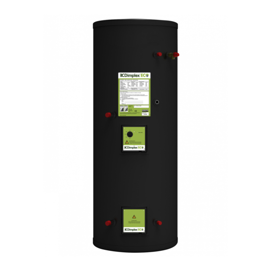
- Page 1 Heat Pump Cylinders without buffer tanks Up to 300L Ec-eau Cylinder Range Installation and User Instructions Important - This manual must be left with the user after Installation!
- Page 2 Dimplex is a licensed member of the Benchmark Scheme which aims to improve the standards of installation and commissioning of domestic heating and hot water systems in the UK and to encourage regular servicing to optimise safety, efficiency and performance.
-
Page 3: Overall View
0 Overall View Figure 1: Overall view of Heat Pump Cylinder installation process Overall View... -
Page 4: Table Of Contents
1 Contents OVERALL VIEW ..................3 CONTENTS ....................4 INTRODUCTION ..................6 SCOPE OF DELIVERY .................. 6 PRE-INSTALLATION ADVICE ................ 7 4.1 R ..................7 ISK ASSESSMENT 4.2 S ................7 ITING CONSIDERATIONS 4.3 C ................... 8 OLD WATER SUPPLY 4.4 B G3 D .......... - Page 5 10 USER INSTRUCTIONS ................28 10.1 G .....................28 ENERAL 10.2 O ..................29 PERATION 10.2.1 Water temperature direct electric heating ........29 10.2.2 Water temperature auxiliary heating ..........30 10.3 M ..................30 AINTENANCE 10.4 T .................31 ROUBLESHOOTING Contents...
-
Page 6: Introduction
2 Introduction 3 Scope of delivery Thank you for choosing a Dimplex Please ensure you check the scope of product. EC-Eau heat pump delivery below before signing any cylinders are specified with large, high delivery documentation. Claims for surface area... -
Page 7: Pre-Installation Advice
- scalding: where appropriate 4 Pre-Installation required thermostatic Advice mixing valve is to be fitted to the hot water outlet of the cylinder (see Please read following section also water borne organisms). carefully before commencing installation. If in any doubt, please - explosion: the unit is fully equipped call appropriate... -
Page 8: Cold Water Supply
- location in relation to remaining 4.3 Cold water supply system components such auxiliary and solar heating system For satisfactory and safe performance of the unvented cylinder the water - frost protection supply must meet following criteria: The heat pump cylinder range is designed floor standing,... -
Page 9: Discharge Pipe D2
4.4.1 Discharge pipe D2 The discharge pipe D2 should be at least one pipe size larger than the nominal outlet size of the safety The discharge pipe (D2) from the device unless total equivalent Tundish should: hydraulic resistance exceeds that of a straight pipe long,... -
Page 10: Worked Example
Table 2: Sizing of copper discharge pipe “D2” for common temperature relief valve outlet sizes 4.4.2 Worked example Therefore the maximum permitted length This example is for a G½ temperature relief valve with a discharge pipe (D2) equates to 5.8m, which is less than (as fitted on 125 to 300L cylinders) the actual length of 7m, therefore having 4 No. -
Page 11: Termination Of Discharge Pipe
- Where a single common discharge - “to a trapped gully with the end of pipe serves more than one system, the pipe below a fixed grating and it should be at least one pipe size above the water seal; larger than the largest individual discharge pipe... -
Page 12: Installation
5.1.3 Expansion vessel required a connection can be taken from the bottom of the inlet group. The expansion vessel is mandatory on Ec-eau cylinders 5.1.5 Drain valve connected directly to the cold water inlet group, utilising the flexible hose... -
Page 13: Hot Water Outlet
- The diameter of discharge pipe (D1) 5.2 Hot Water Outlet should not be less than the nominal outlet size of the safety device, e.g. The hot water pipe work is to be temperature relief valve. directly connected to the hot water outlet connection on the cylinder, see - Where a manifold is used it should Figure 1. -
Page 14: Tundish
5.3.3 Tundish vision mobility, consideration should be given to the installation of a suitable safety device to warn - The tundish should vertical, when discharge takes place, e.g. located in the same space as the electronically operated. unvented hot water storage system and be fitted as close as possible to, Note: To comply with the Water and lower than, the safety device,... -
Page 15: Coil Flow Connections
controller, instead requires 5.6 Coil return connections relay. Equally, if the return connection is the Should it be necessary to remove the lowest point in the heat pump loop, a thermostat from immersion suitable drain device should element, ensure that the contacts are installed. -
Page 16: Sensor
If a non Dimplex heat pump is used in Thermostat combination with this cylinder connection another heat source, a two port valve installation has to be wired after the thermostat, heat pump ensuring compliance with building regulations. temperature sensor The heat pump can be wired to the cylinder in various ways as described by the chosen supplier. -
Page 17: Connection Of The Sensor
5.7.1 Connection of the sensor Step 1: Access the sensor mounting plate. To do this remove the twin thermostat box (A) by removing the screws in the 4 corners only and insulation foam (B) to access the sensor mounting plate (C). Remove the M5 fixing screws. Step 2: The sensor mounting plate will have two vacant slots for additional sensors (D). - Page 18 Step 3: Fit two M5 fixing screws into the cylinder bracket (F). Slide the sensor mounting plate behind the M5 fixing screws (G). Step 4: Insert two remaining M5 screws (H). Tighten the screws until the thermostat bulbs and heat pump sensor are held firmly against the wall of the inner cylinder. Note: there should be no movement in the phials (four clips in the centre of the sensor mounting plate) that are used to hold the bulbs and sensor.
- Page 19 Step 5: Replace the insulating foam over the sensor mounting plate Step 6: Refit the twin thermostat box, taking care not to kink the capillaries that connect the thermostat bulbs to the twin thermostat box. Installation...
-
Page 20: Connection Of Secondary Return
HW Outlet To Taps Secondary Return Swept-T From Taps Figure 6: Secondary return loop secondary return loop must Connection avoid: Secondary Return - stagnant water in long pipe runs A secondary return port is installed on - long waiting times at draw off point the 210, 250 and 300L cylinders. -
Page 21: Commissioning
Close the hot water tap. 6 Commissioning Check all joints for leaks, even time commissioning, those not having been altered complete all relevant sections of the especially when replacing Benchmark Checklist located on the vented cylinder. inside back pages of this document. Open temperature and pressure following commissioning... -
Page 22: Maintenance
Note the set pressure of the 7 Maintenance pressure reducing valve. Remove cartridge and clean strainer in After servicing, complete the relevant water provided in container. Re- Service Record section assemble pressure reducing valve Benchmark Checklist located on the ensuring the correct pressure is inside back pages of this document. -
Page 23: Spare Parts
8 Spare Parts Figure 7: Replacement part numbers for Heat Pump range of cylinders Spare Parts... -
Page 24: Technical Data
9 Technical data Figure 8: Heat Pump Cylinder and Cross-section (for reference only) Heat Pump Cylinder Range Reference Weight (full) [kg] Reheat time [mins]* Average draw off temperature [°C]* Hot water draw off capacity (l)* / draw off flow rate (l/s) 0.25 0.25 0.25... - Page 25 Heat Pump Cylinder Range Reference Actual capacity [L] Materials - inner cylinder Duplex stainless steel LDX2101 - outer cylinder HIPS - inlet/outlet Stainless steel - coils Stainless steel - insulation 60mm PU foam (GWP=1, ODP=0) Maximum operating conditions - potable water temperature 70°C 95°C - heating water temperature...
-
Page 26: Cylinder Heat Exchanger Pressure Drop
9.1 Cylinder heat exchanger pressure drop 2.2m Coil Pressure Drop 45000 40000 35000 30000 25000 20000 15000 10000 5000 Flow Rate (m 2.8m Coil Pressure Drop 60000 50000 40000 30000 20000 10000 Flow Rate (m Figure 9: Heat exchanger pressure drops for 2.2m² and 2.8² coils Technical Data... - Page 27 3.0m Coil Pressure Drop 70000 60000 50000 40000 30000 20000 10000 Flow Rate (m 3.2m Coil Pressure Drop 80000 70000 60000 50000 40000 30000 20000 10000 Flow Rate (m Figure 10: Heat exchanger pressure drop for 3.0m² and 3.2m² coils Technical Data...
-
Page 28: User Instructions
All installations must be notified to 10 User Instructions Local Area Building Control either directly through Competent 10.1 General Persons Scheme. Building Regulations Compliance Certificate will “This appliance is not intended for use then be issued to the customer who by persons (including children) with should, receipt,... -
Page 29: Operation
10.2.1 Water temperature direct 10.2 Operation electric heating Once system been fully Before removing cover commissioned, no user intervention from the immersion heater should be required to fully enjoy the isolate appliance using comfort and benefits of the unvented isolating switch! Danger hot water cylinder. -
Page 30: Water Temperature Auxiliary Heating
10.2.2 Water temperature auxiliary The adjustment at the cylinder is carried out on the twin thermostat heating fitted to the cylinder as shown in Figure 12. In the event that the high The water temperature achieved by temperature cut-out engages, it will the auxiliary heating system depends be necessary to manually reset the on the setting of the thermostat on:... -
Page 31: Troubleshooting
10.4 Troubleshooting Fault Cause Solution A No water A.1 Stop valve closed A.1 Open stop valve from hot A.2 Strainer blocked A.2 Turn water supply off, water taps clean strainer and re- commission A.3 Pressure reducing valve A.3 Re-fit with arrow showing fitted against flow in direction of flow B No hot water... - Page 36 Dimplex a division of GDC Group Ltd Millbrook House Grange Drive, Hedge End, Southampton SO30 2DF Tel.: 0845 600 5111 aftersales@dimplex.co.uk e-mail: www.dimplex.co.uk Notes...
Need help?
Do you have a question about the Ec-eau and is the answer not in the manual?
Questions and answers