Table of Contents
Troubleshooting

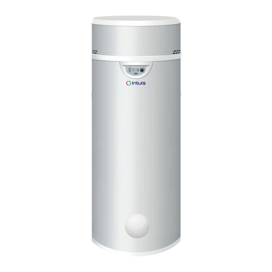
Related Manuals for Dimplex Edel 200 WATER/3


Summary of Contents for Dimplex Edel 200 WATER/3
- Page 1 Edel WATER Domestic hot water heat pump Using calories drawn from the return fl ow of underfl oor heating Installation manual Edel 200 WATER/3 Ref. 352421 Edel 270 WATER/3 Ref. 352431 Made in France Manual ref: 1898865 Edition n : 23.13...
- Page 2 DOMESTIC HOT WATER HEAT PUMP 200L & 270L INSTALLER MANUAL...
-
Page 3: Table Of Contents
TABLE OF CONTENTS 1 - SAFETY ............4 6.5 - Holiday/temporary standby mode ............20 6.6 - BOOST mode (for occasional use and guaranteed comfort) ........20 2 - RECOMMENDATIONS ........6 6.7 - Electric mode (for operation using only the electrical back-up) .20 2.1 - Storage ....................6 6.8 - Programming ..................20 2.2 - Transport ....................6... -
Page 4: Safety
Preserving these documents Danger resulting from improper use • This manual and all other relevant documents should be given to Any work carried out by an unqualifi ed person the system user. may result in damage to the installation or in The system user should keep these manuals for future reference. - Page 5 check for blockages. If the electrical supply cable is damaged, it must be replaced by the manufacturer, their • If the electrical supply cable is damaged, it customer service technicians, or by a qualifi ed must be replaced by the manufacturer, their professional to prevent any risk of injury or customer service technicians, or by a qualifi ed danger.
-
Page 6: Recommendations
2 - RECOMMENDATIONS 2.1 - Storage The appliance can only function when STORAGE PRECAUTIONS: fi lled with water. Never turn on the Admissible storage transport appliance if the tank has not been temperatures of the heat pump water properly fi lled with water and completely heater are from -5°C to +35°C. -
Page 7: Handling
2.3 - Handling 2.4 - Contents of packaging The appliance is supplied with a transport bag, to facilitate handling • 1 domestic hot water heat pump. to the installation site. • 1 hydraulic derivation module. • 1 documentation bag containing 1 installation manual, 1 guarantee card and 3 adjustable feet. -
Page 8: Symbols Used
3 - OPERATING PRINCIPLE The domestic hot water heat pump is a small-capacity heat pump dedicated to the production of domestic hot water. The appliance uses the fl oor’s returns for the capture of calories and then the bonuses to the water of the tank. That is made possible by the use of refrigerant fluid allowing the transfer from one midium to another. -
Page 9: Introduction
4 - INTRODUCTION 4.3 - Technical specifi cations and performances 4.1 - Dimensions Water source heat pump water 200L 270 L heater Heat pump performance Nominal volume Max. input power 1600 1600 Water temperature range +18 to +50 +18 to +50 DHW* temperature with heat pump Max. -
Page 10: Installation
Non-authorised mounting zones for thermodynamic water heaters 5 - INSTALLATION 200 & 270 l: Envelope volume: The envelope volume is the volume that is outside the bathtub 5.1 - Placement and positioning or shower cabin and is limited, on the one hand, by the vertical cylindrical surface circumscribed to the bathtub or shower cabin 5.1.1 - Placement choice and, on the other hand, to the horizontal plane located at 2,25m... -
Page 11: Options
5.1.3 - Options 5.2 - Hydraulic connections to the underfl oor heating circuit 5.1.3.1 - Primary circuit mixing valve The appliance is connected using the return fl ow of the underfl oor heating network via a derivation module provided with the tank. Primary circuit 5.2 .1 - Underfl oor heating derivation module thermostatic mixing... -
Page 12: 3-Way Mixing Valve For Underfl Oor Heating Circuit
5.2.5 - 3-way mixing valve for underfl oor heating circuit imperative With the presence of a 3-way mixing valve (rep.16), it is to place the derivation kit between the underfl oor heating collector and the 3-way valve bypass as indicated on the diagram below: DOMESTIC HOT WATER HEAT PUMP 200L &... -
Page 13: Thermostatic Mixing Valves Equipping The Water Loops Of The
5.2.10 - Treatment of the heating circuit 5.2.6 - Thermostatic mixing valves equipping the water loops of the underfl oor heating circuit Central heating systems MUST BE CLEANED to eliminate debris (copper, If there are thermostatically controlled valves equipping the fi bres, soldering fl uxes) related to set- recirculating pumps for the underfloor heating circuit on the appliance, (rep.18), leave them permanently open (by manually... -
Page 14: 11- Purging The Installation
Domestic hot water pipes with a cast-iron or steel link, or with 5.2.11 - Purging the installation dielectric connections (not supplied) to avoid an iron/copper galvanic The oxygen present in the air is extremely corrosive. Therefore, bridge. for a permanent purging of the installation to be effective, •... -
Page 15: Electrical Connections
A. Domestic hot water (DHW) Domestic cold water (DCW) C. Underfl oor heating D. Vers retour générateur de chauff age Primary circuit mixing valve To the heating unit return Stop valve Pressure reducer Check valve Insulating dielectric sleeve (not supplied) Pressure-relief membrane valve (not supplied) Run-off siphon Domestic expansion vessel... -
Page 16: External Control
5.4.2 - External control 5.4.2.2 - Electricity provider contact To prevent the electrical back-up from running during peak hours, connect the dry contact originating from the electricity counter, to terminal 1. Only an external connection using a voltage free «dry contact» is authorised, - Contact open = Back-up not allowed to run otherwise there is a risk of damaging the - Contact closed = Back-up allowed to run... -
Page 17: Connection To The Photovoltaic (Pv) Function
5.4.1.3 - Connection to the photovoltaic (PV) function Energy manager dry contact Tair Tdégiv Teau PV max PV éco This func tion enables the appliance to operate in auto -produc tion mode, which means that it will use the energy produced by the PV function to supply the heat pump as well as the electrical back-up, and to heat the water in the tank. -
Page 18: Set-Up And Use
6 - SET-UP AND USE 6.1 - Control panel Deterioration risk: it is imperative to fi ll the tank with water before switching on the appliance or connecting it to the electrical supply. • Leave the appliance unplugged. • Open the hot water valve located at the highest point of the installation. -
Page 19: Setting The Date And Time
6.4 - Setting the desired water 6.3 - Setting the date and time temperature • Press «Clock settings» 6.4.1 - PV mode deactivated The water temperature can be adjusted from 30°C to 65°C. Up to 2 6 / 0 9 / 1 1 60°C, the water is heated using only the heat pump. -
Page 20: Holiday/Temporary Standby Mode
6.5 - Holiday/temporary standby mode 6.6 - BOOST mode (for occasional use and guaranteed comfort) hol i d a y « » mode puts the appliance on standby while the frost protection mode remains active. This function can be programmed boost The «... -
Page 21: Installer Menu
• Yes: the signals from terminals 1 and 2 have priority over frost 6.9 - INSTALLER menu protection and eco mode. • No: frost protection and eco mode have priority over the signals It may be necessary to adjust certain temperature settings to from terminals 1 and 2. -
Page 22: Anti-Bact
load shedding ANTI-BACT 6.9.3.3 - Level of operation 6.9.3.1 - Anti-legionellosis cycle authorised during peak time anti bact Factory setting - water temp. 60 C When load shedding is activated you can choose to prevent certain Factory setting - elements from running (Electrical back-up and compressor). A N TI -B A CT AN TI -BAC T Confi rm... -
Page 23: Locking The Keyboard
6.9.4 - Locking the keyboard 6.9.5 - Resetting the parameters Automatic and permanent locking Resetting the parameters allows you to return to the default settings. The «locking» menu enables you to create three possible levels of locking for accessing the menus. Go to the «Installer menu», and turn the dial to «Reset PARa.». -
Page 24: Maintenance And Troubleshooting
7 - MAINTENANCE AND .../... → In case of intervention on the TROUBLESHOOTING refrigerant circuit: In order to maintain effi ciency and improve durability it 1) Secure the area you will be working in. is advised that an annual maintenance check be carried 2) Inform people of the potential danger involved out by a qualifi ed professional. -
Page 25: Drainage
• The following procedure must be followed : - Remove the refrigerant ; Neglecting to clean the electronic circuit - Purge the circuit with inert gas ; board and the electrical components could create a source of ignition. - Evacuate to the atmosphere; - Purge with inert gas ;... -
Page 26: Recovery
d) Perform a «pump down» on the appliance where possible. 7.6.6 - Recycling and Disposal e) If it is not possible to vacuum, make a manifold so that the • The product must be labelled indicating that it has been taken out refrigerant can be removed from various parts of the system. -
Page 27: Troubleshooting
7.7 - Troubleshooting Do not adjust • Not hot water settings on the safety aquastat Check that: • The volume of water consumed is not higher than the volume in the tank. Reset button (87°C) • The time period that the appliance operates is not too short on safety aquastat (12h minimum if connected to piping). -
Page 28: List Of Spare Parts
7.9 - List of spare parts Rep. Description 200/270L Regulation / display B4993549 Control panel display B1242042 C3S electronic circuit board controller B1244522 Temperature sensor - lg 900mm B1244552 Temperature sensor - lg 900mm Temperature sensor - lg 700mm B1244577 (200L model) Temperature sensor - lg 1200mm B1244575... -
Page 29: Error Message Codes: Errors, Solutions And Operating In Case Of Error
7.10 - Error message codes: errors, solutions and operating in case of error Note: Errors can be dismissed by briefl y pressing the dial (manual reset) Temporary operating Display Error Probable causes measures while waiting for Solutions the problem to be resolved •Voltage too high on electrical network •Electronic board defect •Wiring error during electrical connection... -
Page 30: Warranty
8 - WARRANTY 8.1.2.3 - Placement Cases (not limited to) where the warranty is void: The tank is guaranteed against breakage for a period of fi ve (5) years, • Placing the appliance where it can be subject to frost or other starting from the date the appliance was activated, if the warranty adverse weather conditions. -
Page 31: Appendix
9 - APPENDIX 9.1 - Wiring diagram HP - High pressure - pressure switch RE - Electrical resistance UTL - Electrical back-up temperature limiting safety thermostat AqL - Electrical back-up safety aquastat HPS - High pressure - pressure switch DOMESTIC HOT WATER HEAT PUMP 200L & 270L INSTALLER MANUAL... - Page 32 NOTES : Industrial and Development site Rue de la République CS 40029 80210 Feuquières-en-Vimeu Spare Parts Department Tel. : 03 22 61 21 21 Fax : 03 22 61 33 35 E-mail : pieces@auer.fr Technical Assistance Department* E-mail : enr@auer.fr *Technical assistance is reserved for professionals...
Need help?
Do you have a question about the Edel 200 WATER/3 and is the answer not in the manual?
Questions and answers