
Related Manuals for Dimplex ECSd125-580


Summary of Contents for Dimplex ECSd125-580
- Page 1 Direct Electric and Indirect Cylinders Up to 300L EC-Eau Cylinder Range Installation and User Instructions Important - This manual must be left with the user after Installation!
- Page 2 Dimplex is a licensed member of the Benchmark Scheme which aims to improve the standards of installation and commissioning of domestic heating and hot water systems in the UK and to encourage regular servicing to optimise safety, efficiency and performance.
-
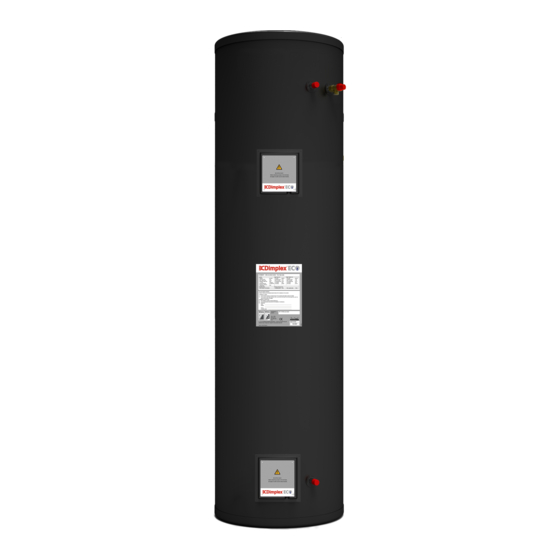
Page 3: Overall View
0 Overall View Figure 1: Overall view of Direct Electric Cylinder Installation Process Overall View... - Page 4 Figure 2: Overall view of Indirect Cylinder Installation Process Overall View...
-
Page 5: Table Of Contents
1 Contents Overall View ....................3 Contents ....................5 Introduction ....................7 Scope of delivery ..................7 Pre-Installation Advice .................9 4.1 Risk assessment ..................9 4.2 Siting considerations ................9 4.3 Cold water supply .................. 10 4.4 Building regulation G3 Discharge requirements .......... 11 4.4.1 Discharge pipe D2................12 4.4.2 Worked example ................ - Page 6 10 User Instructions..................34 10.1 General ..................... 34 10.2 Operation ..................35 10.2.1 Water temperature direct electric heating ........... 35 10.2.2 Water temperature auxiliary heating ..........36 10.3 Maintenance ..................36 10.4 Troubleshooting .................. 37 Contents...
-
Page 7: Introduction
2 Introduction WARNING: Dimplex cannot take responsibility for ensuring safe operation of the appliance outside Thank you for choosing a Dimplex of the scope of intended use. product. The EC-Eau direct electric and indirect cylinders are specified with 3 Scope of delivery... - Page 8 * These items are supplied factory fitted Table 3: Scope of Delivery for Indirect Cylinders Scope of Delivery...
-
Page 9: Pre-Installation Advice
Pre-Installation - scalding: where appropriate required thermostatic Advice mixing valve is to be fitted to the hot water outlet of the cylinder (see also Please read following section water borne organisms). carefully before commencing installation. If in any doubt, please call - explosion: the unit is fully equipped appropriate help... -
Page 10: Cold Water Supply
4.3 Cold water supply - frost protection For satisfactory and safe performance The direct electric and indirect cylinder of the unvented cylinder the water ranges designed floor supply must meet following standing, vertically mounted, indoors criteria: and in a frost free environment. The cylinder may be located on any flat and Minimum dynamic 150 kPa... -
Page 11: Building Regulation G3 Discharge Requirements
Dimplex recommend annual 4.4 Building regulation G3 maintenance inspection is carried out Discharge on the domestic hot water cylinder. In requirements hard water areas this should include inspection of the heat exchanger and As part of the requirements of Building... -
Page 12: Discharge Pipe D2
4.4.1 Discharge pipe D2 Dimplex strongly recommends the use of metal pipework only and Dimplex does not take responsibility for any The discharge pipe (D2) from the damage caused from discharges. Tundish should: The discharge pipe D2 should be at - “have a vertical section of pipe at... -
Page 13: Worked Example
Table 4: Sizing of copper discharge pipe “D2” for common temperature relief valve outlet sizes 4.4.2 Worked example Therefore the maximum permitted length This example is for a G½ temperature relief valve with a discharge pipe (D2) equates to 5.8m, which is less than the (as fitted on 125 to 300L cylinders) actual length of 7m, therefore calculate having 4 No. -
Page 14: Termination Of Discharge Pipe
- Where a single common discharge 4.4.3 Termination pipe serves more than one system, discharge pipe it should be at least one pipe size larger than the largest individual - “The discharge pipe (D2) from the discharge pipe (D2) to be connected. tundish should terminate in a safe place where there is no risk to - The discharge pipe should not be... -
Page 15: Limitations
4.5 Limitations the water cylinder and the cold water inlet group. Due to the operating temperatures of Furthermore, it is recommended to direct electric water heaters the water mount the vessel higher than the hardness can considerably influence cylinder to avoid having to drain the the longevity of the immersion heater cylinder when... -
Page 16: Balanced Cold Water Supply
5.2.1 Thermostatic mixing Cold valve Water Balanced from Cold Water Mains Supply A thermostatic mixing valve may be required limit outlet temperature. In this case, the valve Expansion should installed following Vessel manufacturer’s instructions, ensuring Connection none of the safety equipment has been isolated, (i.e. -
Page 17: Discharge Pipe D2
(Dimplex part occupied by people with impaired number R00836-1). vision mobility, consideration should be given to the installation of 5.3.2 Discharge pipe D2 a suitable safety device to warn when discharge takes place, e.g. -
Page 18: Immersion Heater
5.4 Immersion heater Coil flow connections (indirect models only) The immersion heater has to be connected in accordance with IEE If the flow connection is the highest Wiring Regulations and the installer point in the indirect heating loop and if carrying out the work has to be suitably the system was not commissioned qualified. -
Page 19: Thermostat Connection (Indirect Models Only)
Thermostat To conform to building regulations, it is imperative that any heat generator connection (indirect connected to the cylinder is installed models only) through the correct twin thermostat, which is factory fitted to the cylinder. The indirect heating source can be The two port valve supplied with the connected to the cylinder in various indirect cylinder is to be installed by... - Page 20 Figure 8: Auxiliary loop wiring details - 2 x two port valves Installation...
- Page 21 Figure 9: Auxiliary loop wiring details – Three port mid-position + 2 port valve Installation...
-
Page 22: Connection Of Secondary Return
Connection - stagnant water in long pipe runs Secondary Return - long waiting times at draw off point for hot water For cylinders that do not have a dedicated secondary return - undue water wastage connection, it is possible to install a secondary return by connecting a To minimise the energy consumption of swept - T to the cold water inlet of the... -
Page 23: Commissioning
6 Commissioning Close the hot water tap. Check all joints for leaks, even time commissioning, those not having been altered complete all relevant sections of the especially when replacing a vented Benchmark Checklist located on the cylinder. inside back pages of this document. Open temperature and pressure following commissioning... -
Page 24: Maintenance
7 Maintenance Note the set pressure of the pressure reducing valve. Remove cartridge and clean strainer in After servicing, complete the relevant water provided in container. Re- Service Record section assemble pressure reducing valve Benchmark Checklist located on the ensuring the correct pressure is inside back pages of this document. - Page 25 CLEANING INSTRUCTIONS: Clean outer cladding cylinder with soft cloth dampened with warm water only. Do not use abrasive or aggressive cleaning materials, such as alcohol or petroleum based solvents, as this may damage the surface of the product. Waste electrical products should not be disposed of with household...
-
Page 26: Spare Parts
8 Spare Parts Figure 11: Replacement part numbers for Direct Electric and Indirect range of cylinders * ECSd125-580 & ECSd150-580 only, **ECSd210-580 only, ***ECSd250-580 & ECSd300-580 only Spare Parts... -
Page 27: Technical Data And Product Fiche
9 Technical Data and Product Fiche Figure 12: Direct Electric Cylinder and Cross-section (for reference only) Technical Data... - Page 28 Direct Electric Cylinder Range - Dimensions Reference Weight [kg] Reheat time [mins]* Heat Loss [kWh] 0.95 1.10 1.41 1.51 1.96 Height [mm] 1115 1490 1765 2065 Outer Diameter [mm] HW Outlet [mm] 1265 1540 1840 T&P valve [mm] 1265 1540 1840 CW Inlet [mm] Bottom Immersion [mm]...
- Page 29 Direct Electric Cylinder Range – Product Features Materials - inner cylinder Duplex stainless steel LDX2101 - outer cylinder HIPS - inlet/outlet Stainless steel - insulation 60mm PU foam (GWP=1, ODP=0) Maximum operating conditions - potable water temperature 70°C - operating pressure 3 bar Cold water supply - minimum dynamic pressure...
- Page 30 Figure 13: Indirect Cylinder and Cross-section (for reference only) Technical Data...
- Page 31 Indirect Cylinder Range – Product Dimensions Reference Weight [kg] Reheat time [mins]* HX performance [kW]* Heat Loss [kWh/24h]* 0.95 1.10 1.41 1.51 1.96 Height [mm] 1115 1490 1765 2065 Outer Diameter [mm] HW Outlet [mm] 1265 1540 1840 T&P valve [mm] 1265 1540 1840...
- Page 32 Indirect Cylinder Range – Product Features Materials - inner cylinder Duplex stainless steel LDX2101 - outer cylinder HIPS - inlet/outlet Stainless steel - coils Stainless steel - insulation 60mm PU foam (GWP=1, ODP=0) Maximum operating conditions - potable water temperature 70°C - heating water temperature 95°C...
-
Page 33: Cylinder Heat Exchanger Pressure Drop
9.1 Cylinder heat exchanger pressure drop 0.5m Coil Pressure Drop 80000 70000 60000 50000 40000 30000 20000 10000 Flow Rate (m 0.8m Coil Pressure Drop 100000 90000 80000 70000 60000 50000 40000 30000 20000 10000 Flow Rate (m Figure 14: Heat exchanger pressure drops for 0.5m² and 0.8m² coils Technical Data... -
Page 34: User Instructions
10 User Instructions All installations must be notified to Local Area Building Control either directly through Competent 10.1 General Persons Scheme. Building Regulations Compliance Certificate will “This appliance is not intended for use then be issued to the customer who by persons (including children) with should, receipt,... -
Page 35: Operation
10.2 Operation 10.2.1 Water temperature direct electric heating Once system been fully commissioned, no user intervention Before removing cover should be required to fully enjoy the from the immersion heater comfort and benefits of the unvented isolate appliance using hot water cylinder. isolating switch! Danger... -
Page 36: Water Temperature Auxiliary Heating
10.2.2 Water temperature The adjustment at the cylinder is carried out on the twin thermostat auxiliary heating fitted to the cylinder as shown in Figure event that high The water temperature achieved by the temperature cut-out engages, it will be auxiliary heating system depends on necessary manually... -
Page 37: Troubleshooting
10.4 Troubleshooting Fault Cause Solution A No water A.1 Stop valve closed A.1 Open stop valve from hot A.2 Strainer blocked A.2 Turn water supply off, clean water taps strainer and re-commission A.3 Re-fit with arrow showing in A.3 Pressure reducing direction of flow valve fitted against flow... - Page 38 Notes...
- Page 39 Notes...
- Page 44 Dimplex a division of GDC Group Ltd Millbrook House Grange Drive, Hedge End, Southampton SO30 2DF Tel.: 0845 600 5111 aftersales@dimplex.co.uk e-mail: www.dimplex.co.uk...
Need help?
Do you have a question about the ECSd125-580 and is the answer not in the manual?
Questions and answers