Sign In
Upload
Download
Table of Contents
Contents
Add to my manuals
Delete from my manuals
Share
URL of this page:
HTML Link:
Bookmark this page
Add
Manual will be automatically added to "My Manuals"
Print this page
×
Bookmark added
×
Added to my manuals
Manuals
Brands
Dimplex Manuals
Water Heater
EDL200UK-630RF
Installation and user instructions manual
Dimplex EDL200UK-630RF Installation And User Instructions Manual
Air source heat pump water heater
Hide thumbs
1
2
Table Of Contents
3
4
5
6
7
8
9
10
11
12
13
14
15
16
17
18
19
20
21
22
23
24
25
26
27
28
29
30
31
32
33
34
35
36
page
of
36
Go
/
36
Contents
Table of Contents
Troubleshooting
Bookmarks
Table of Contents
Table of Contents
Manual Warnings
Safety Information
Introduction
Control App
Scope of Delivery
Pre-Installation
Handling
Unpacking
Pipework
Taps and Fittings
Risk Assessment
Siting Considerations
Cold Water Supply
Building Regulation G3
Discharge Pipe D2
Worked Example
Termination of Discharge Pipe
Product Disposal
Installation
Cold Water Inlet with Inlet
Install the Inlet Group
Expansion Vessel
Balanced Cold Water Supply
Drain Valve
Thermostatic Mixing Valve
Pipe Insulation
Discharge Pipes from Safety Devices 6.4.1 Discharge Pipe D1
Discharge Pipe D2
Tundish
Hot Water Outlet
Immersion Heaters
Air Connection
Worked Example
Ducting Design
Condensates Draining
Electrical Connections
Accessing Electrical Connections
Electricity Provider Contact
Connecting the PV Function
Set-Up and Use
Commissioning
Using Your Hot Water Heat Pump
Control Box
Setting the Language
Setting the Time
Setting the Water Temperature
Standby Mode
Boost Function
Electric Mode
Programming
Installer Menu
PV Mode
Adjusting the Operating Settings
Anti-Bacteria
Fan Mode
Minimum Temperature
Shedding
Maximum Heating Time
Locking the Keypad
Resetting Parameters
Reading Display
Counters (Meters)
Control App
Home Screen
Holiday Mode
Schedule Control
Hygiene Mode
Maintenance
DHW Cylinder
Heat Pump
Air Intake & Exhaust
Heat Pump Condensation
Electrical Connections
Troubleshooting
Spare Parts
Error Codes
Warranty
Warranty Limits
Advertisement
Quick Links
1
Error Codes
Download this manual
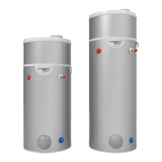
Edel RF
Air Source Heat Pump Water Heater
Installation and User Instructions
RD01144-2
Important - This manual must be left with user after Installation!
Table of
Contents
Previous
Page
Next
Page
1
2
3
4
5
Advertisement
Table of Contents
Need help?
Do you have a question about the EDL200UK-630RF and is the answer not in the manual?
Ask a question
Questions and answers
Related Manuals for Dimplex EDL200UK-630RF
Water Heater Dimplex ESSW2 Owner's Manual
Solar domestic water heating system (134 pages)
Water Heater Dimplex Ec-eau Installation And User Instructions Manual
Heat pump cylinders without buffer tanks ec-eau series (36 pages)
Water Heater Dimplex ECSd125-580 Installation And User Instructions Manual
Direct electric and indirect cylinders up to 300l. ec-eau cylinder range (44 pages)
Water Heater Dimplex Edel EDL200UK-630 Installation And User Instructions Manual
Air source heat pump water heater (36 pages)
Water Heater Dimplex Edel EDL270UK-630 Installation And User Instructions Manual
Air source heat pump water heater (36 pages)
Water Heater Dimplex EDL170-520RF Installation And User Instructions Manual
Air source heat pump water heater (36 pages)
Water Heater Dimplex 500001099 Installation And User Instructions Manual
Air source heat pump water heater (40 pages)
Water Heater Dimplex EDL270UK-630RF Installation And User Instructions Manual
Air source heat pump water heater (36 pages)
Water Heater Dimplex LBW 300 Installation And Operating Manual
Heat pump water heater with airduct connection and 3-speed radial fan (24 pages)
Water Heater Dimplex DHWE 50S Installation And Operating Instructions Manual
Wall mounted smart (16 pages)
Water Heater Dimplex WWSP 335 Installation And Operating Instruction Manual
300-700 litre domestic hot water cylinder for heat pumps (32 pages)
Water Heater Dimplex DEE 1803 Installation And Operating Instructions Manual
Instantaneous water heater (41 pages)
Water Heater Dimplex PWD 750 Installation And Operating Instructions Manual
Combo tank 750 litre (40 pages)
Water Heater Dimplex SCx175sd Installation And Operation Manual
Solar unvented water heaters (16 pages)
Water Heater Dimplex SUTP Mid Range Installation Manual
Sutp mid range unvented hot water heaters 30,50 & 75 litres (14 pages)
Water Heater Dimplex SCxn175sd Installation And Operating Instructions Manual
Unvented hot water cylinder (28 pages)
This manual is also suitable for:
Edl270uk-630rf
Table of Contents
Print
Rename the bookmark
Delete bookmark?
Delete from my manuals?
Login
Sign In
OR
Sign in with Facebook
Sign in with Google
Upload manual
Upload from disk
Upload from URL


Need help?
Do you have a question about the EDL200UK-630RF and is the answer not in the manual?
Questions and answers