Table of Contents
Advertisement
Advertisement
Table of Contents

Subscribe to Our Youtube Channel
Related Manuals for LG-Nortel ipecs

Summary of Contents for LG-Nortel ipecs
- Page 1 Hardware Description & Installation Manual...
-
Page 2: Ipecs Release
Copyright Laws. LG-Nortel reserves the right to make changes in specifications at any time without notice. The information furnished by LG-Nortel in this material is believed to be accurate and reliable, but is not warranted to be true in all cases. -
Page 3: Revision History
IPECS Release 5 Hardware Description & Installation Issue 5.0 Revision History ISSUE DATE DESCRIPTION OF CHANGES 28 Oct. 2002 Initial Release for standard version 08 Sep. 2003 Change the model name from LiK-100 to LiK-300 Add Gateway Module (MFIME, VOIM, PRIM, RSGM) 09 Feb. -
Page 4: Table Of Contents
Release 5 Hardware Description & Installation Issue 5.0 Table of Contents 1 INTRODUCTION .................. 1 1.1 iPECS Overview ....................1 1.2 Hardware Components Chart ................3 2 HARDWARE DESCRIPTION ..............5 2.1 iPECS Modules ....................5 2.1.1 MFIMs (Multi-Function Interface gateway Module)............5 2.1.2... - Page 5 IPECS Release 5 Hardware Description & Installation Issue 5.0 3.1 System Capacity ....................42 3.1.1 Dimension and Weight....................43 3.1.2 Environment specification..................43 3.1.3 Electrical specification ....................44 3.1.3.1 System Electrical specification ................... 44 3.1.3.2 Module Power Requirements ..................... 44 3.1.3.3...
- Page 6 IPECS Release 5 Hardware Description & Installation Issue 5.0 4.5.13 PRIM Installation......................89 4.5.14 VMIM Installation ....................... 91 4.5.15 MCIM Installation ....................... 92 4.5.16 RSGM Installation...................... 93 4.5.17 POE8 Installation ....................... 97 4.5.18 WTIM4/8 Installation ....................99 4.6 MAIN CABINET WIRING ................102...
- Page 7 Hardware Description & Installation Issue 5.0 List of Figures Figure 1.1-1 iPECS Structure .................. 2 Figure 2.1.2-1 VOIM8 & 24 Front & Rear Panels ..........7 Figure 2.1.3.1-1 LGCM4 Front & Rear Panels ............8 Figure 2.1.3.2-1 LGCM8 Front & Rear Panels ............9 Figure 2.1.4-1 DIDM8 Front &...
- Page 8 Figure 4.5.1.4-1 Module Grounding............... 65 Figure 4.5.1.5-1 Telephony (RJ-11 or RJ-45) Connector Pin Assignment..65 Figure 4.5.1.6-1 LAN Connector (RJ-45) Pin Assignment........66 Figure 4.5.1.7-1 iPECS LAN Wiring ..............68 Figure 4.5.1.7-2 Erroneous Loop Wiring .............. 68 Figure 4.5.1.8-1 RS-232 DB-9 Pin-outs .............. 69 Figure 4.5.2-1 MFIM100 Miscellaneous Function Connections ......
- Page 9 IPECS Release 5 Hardware Description & Installation Issue 5.0 Figure 4.7-2 LIP-8000 DSS Installation.............. 108 Figure 4.7-3 LIP-8000 DSS Installation (12DSS + 48DSS)....... 108 Figure 4.7-4 LIP-8000 DSS Installation (12DSS + 12LS) ......... 109 Figure 4.7-5 LIP-8000 DSS Installation (12DSS + 12LSS+48DSS) ....109 Figure 4.7-6 LIP-7000 Wall Mount Installation ..........
- Page 10 Release 5 Hardware Description & Installation Issue 5.0 List of Tables Table 1.2-1 iPECS Modules and Terminals ............3 Table 2.1.1-1 MFIMs Comparison Chart ..............5 Table 2.2-1 LIP Phones ..................27 Table 3.1-1 System Capacities................42 Table 3.1.1-1 Dimensions and Weight ..............43 Table 3.1.2-1 Environmental Specifications ............
-
Page 11: Introduction
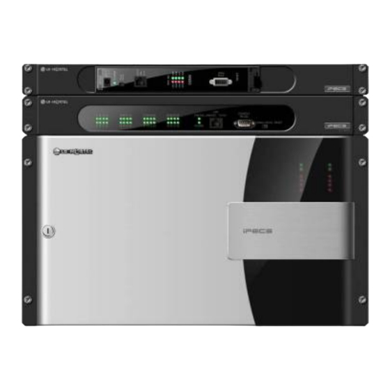
The modules, which make up the iPECS, can be installed in a Main Cabinet. The cabinet can be desk, 19” rack, or wall mounted, as best fits the user needs and equipment room. Each of the system’s modules is powered from a PSU, which converts 100-240 VAC to 48 VDC. -
Page 12: Figure 1.1-1 Ipecs Structure
The reliability, extensive feature content, the ability to support present and future applications with the iPECS Feature Server and the capability to use an array of modules and instruments, permit the iPECS to be tailored to meet the short and long term needs of the most demanding customer requirements. -
Page 13: Hardware Components Chart
Hardware Description & Installation Issue 5.0 Hardware Components Chart Table 1.2-1 provides a description of the hardware components that make-up iPECS. All of the iPECS Modules and terminals are connected over a 10/100 Base-T Ethernet LAN. Table 1.2-1 iPECS Modules and Terminals... - Page 14 LIP DSS Console with 12 buttons, w/12-line LCD button label LIP-7004WMK Wall Mount Kit for LIP-7004N LIP-7008WMK Wall Mount Kit for 7008D LIP-7024WMK Wall Mount Kit for LIP-7016D, 7024D & 7024LD WIT-300HE iPECS WLAN Phone GDC-400B DECT Base Station GDC-400H DECT Handset...
-
Page 15: Hardware Description
MFIMs have a 10/100 Base-T Ethernet interface, the “LAN1” RJ-45 type connector, which is the interface to the iPECS call server features and functions. Each MFIM has a second 10/100 Base-T Ethernet interface “LAN2” RJ-45 type connector. The “LAN2” port is employed for redundant processor operation. - Page 16 IPECS Release 5 Hardware Description & Installation Issue 5.0 • Power status LED, • RCA jack for one music (audio) source -BGM1-, • One (1) “LAN1” RJ-45 Female LAN connector with Speed and Link/Activity LEDs, • One (1) “LAN2” RJ-45 Female LAN connector with Speed and Link/Activity LEDs, •...
-
Page 17: Voim8 & 24 (Voice Over Ip Gateway Modules)
The eight (8) and twenty-four (24) channel Voice over IP gateway Module (VOIM8 and VOIM24) perform packet translation between standard H.323 or SIP protocol and the iPECS proprietary protocol. The VOIM8 contains a single processor to support eight (8) VoIP calls. The VOIM24 contains 2 processors to support maximum twenty-four (24) VoIP calls. -
Page 18: Lgcms (Loop Start Co Gateway Module)
IPECS Release 5 Hardware Description & Installation Issue 5.0 2.1.3 LGCMs (Loop Start CO gateway Module) 2.1.3.1 LGCM4 The four (4)-port Loop Start CO gateway Module (LGCM4) provides four (4) CO/PBX Loop Start Line interfaces. These interfaces support pulse or DTMF dial signals. Each Interface contains ring and loop current detection circuits, speech codec and compression functions and loop signaling circuits. -
Page 19: Lgcm8
IPECS Release 5 Hardware Description & Installation Issue 5.0 2.1.3.2 LGCM8 The eight (8)-port Loop Start CO gateway Module (LGCM8) provides eight (8) CO/PBX Loop Start Line interfaces. These interfaces support pulse or DTMF dial signals. Each Interface contains ring and loop current detection circuits, speech codec and compression functions, and loop signaling circuits. -
Page 20: Didm8 (Did Gateway Module)
IPECS Release 5 Hardware Description & Installation Issue 5.0 2.1.4 DIDM8 (DID gateway Module) The eight (8)-port Direct-In-Dial gateway Module (DIDM8) provides interfaces to Direct-In-Dial Lines, supporting wink or immediate start signaling. These special PSTN lines are incoming only and send the last few digits of the dialed number to the DIDM8 identifying a particular extension/user in the system. -
Page 21: Dtim8 (Digital Terminal Interface Gateway Module)
The eight (8)-channel Digital Terminal Interface gateway Module supports 8 digital keysets (LKD and LDP models). Keysets have access to all the resources of the iPECS as well as keyset functionality and simple one-button feature access. The DTIM8 contains a processor for IP to TDM and signaling conversion as well as DSP circuitry to provide transcoding for each channel. -
Page 22: Sltms (Single Line Telephone Gateway Module)
IPECS Release 5 Hardware Description & Installation Issue 5.0 2.1.6 SLTMs (Single Line Telephone gateway Module) 2.1.6.1 SLTM4 The four (4)-port Single Line Telephone Module (SLTM4) allows standard analog Single Line Telephone (SLT) devices access to CO Lines, other stations, and most features of the system through the use of “dial codes”. -
Page 23: Sltm8
IPECS Release 5 Hardware Description & Installation Issue 5.0 2.1.6.2 SLTM8 The eight (8)-port Single Line Telephone Module (SLTM8) allows standard analog Single Line Telephone (SLT) devices access to CO Lines, other stations, and most features of the system through the use of “dial codes”. The SLTM8 provides interface circuitry for eight (8) SLTs. Each interface is equipped with appropriate speech codec and compression functions, 48 volt DC feed circuit, pulse and DTMF dial signal detection. -
Page 24: Sltm32
IPECS Release 5 Hardware Description & Installation Issue 5.0 2.1.6.3 SLTM32 The thirty-two (32)-port Single Line Telephone Module (SLTM32) allows standard analog Single Line Telephone (SLT) devices access to CO Lines, other stations, and most features of the system through the use of “dial codes”. The SLTM32 provides interface circuitry for thirty-two (32) SLTs. -
Page 25: Brims (Bri Gateway Module)
IPECS Release 5 Hardware Description & Installation Issue 5.0 2.1.7 BRIMs (BRI gateway Module) 2.1.7.1 BRIM2 The Basic Rate Interface gateway Module (BRIM2) has two (2) ISDN Basic Rate Interface ports (2B+D). This Module supports the ‘T’ interface as described by ETSI 300.012 based on the ITU- T Recommendations I.430, and can be installed in the TE (Terminal Equipment) mode. -
Page 26: Brim4
IPECS Release 5 Hardware Description & Installation Issue 5.0 2.1.7.2 BRIM4 The Basic Rate Interface gateway Module (BRIM4) has four (4) ISDN Basic Rate Interface ports (2B+D). The BRIM4 supports the ‘T interface’ as described by ETSI 300.012 based on the ITU-T Recommendations I.430, and can be installed in the TE (Terminal Equipment) mode. -
Page 27: Prim (Pri Gateway Module)
IPECS Release 5 Hardware Description & Installation Issue 5.0 2.1.8 PRIM (PRI gateway Module) The PRIM module provides one (1) PRI interface. This interface supports 30 PCM bearer and 2 signaling channels for PRI. The PRIM gateway is comprised of two boards, a main board and a daughter board, the PCEU. -
Page 28: Vmim (Voice Mail Interface Module)
The VMIM (Voice Mail Interface Module) provides mid-range Auto Attendant/Voice Mail services for the iPECS, primarily intended to support the MFIM600 but can be employed with any MFIM. The VMIM contains a processor and DSP circuitry to support 8 simultaneous channels and memory to support 9 hours of voice storage capacity. -
Page 29: Mcim (Multi-Media Conference Interface Gateway Module)
IPECS Release 5 Hardware Description & Installation Issue 5.0 2.1.10 MCIM (Multi-Media Conference Interface gateway Module) The Multi-Media Conference Interface gateway Module (MCIM) permits users to establish multi- party voice conferences with up to 32 simultaneous parties using the g.711 or g.729 codec and 24 parties with the g.723 codec. -
Page 30: Rsgm (Remote Services Gateway Module)
2.1.11 RSGM (Remote Services Gateway Module) The Remote Services Gateway Module (RSGM) transparently extends iPECS services to users and interfaces over broadband IP networks. Remote Services are implemented with the iPECS Remote Services Application Server employing the system’s VoIP channels to communicate with remote LIP Phones and RSGMs. -
Page 31: Figure 2.1.11-2 Rsgm Front & Rear Panels
IPECS Release 5 Hardware Description & Installation Issue 5.0 As shown in Figure 2.1.11-2, the front panel of the RSGM has: • Power status LED, • RCA jack for external music (audio) source -BGM-, • Eight (8) LEDs, • RJ-45 Female LAN connector with Speed and Link/Activity LEDs for WAN connection, •... -
Page 32: Poe8 (Power Over Ethernet Switching Hub)
IPECS Release 5 Hardware Description & Installation Issue 5.0 2.1.12 POE8 (Power Over Ethernet switching hub) The Power over Ethernet Switching Module (POE8) has eight (8) LAN ports and an UPLINK LAN port, all of which employ Ethernet switching. All ports support Auto-sense 10/100Mbps, half/full duplex mode and auto MDI/MDIX function. -
Page 33: Wtim (Wireless Telephone Interface Module)
IPECS Release 5 Hardware Description & Installation Issue 5.0 2.1.13 WTIM (Wireless Telephone Interface Module) 2.1.13.1 WTIM4 The four (4)-channel Wireless Terminal Interface gateway Module (WTIM4) provides four (4) interfaces for GDC-400B, which is a DECT base station classified as the Remote Fixed Part (RFP) in the DECT specification. -
Page 34: 2.1.13.2 Wtim8
IPECS Release 5 Hardware Description & Installation Issue 5.0 2.1.13.2 WTIM8 The eight (8)-channel Wireless Terminal Interface gateway Module (WTIM8) provides eight (8) interfaces for the GDC-400B, which is a DECT base station classified as the Remote Fixed Part (RFP) in the DECT specification. DECT handsets can be used if the GDC-400B is connected to the WTIM8 and the proper attendant programming is completed. -
Page 35: Psu (Power Supply Unit)
IPECS Release 5 Hardware Description & Installation Issue 5.0 2.1.14 PSU (Power Supply Unit) The Power Supply Unit (PSU) converts 100-240 VAC @ 50/60 Hz to -48V and 5V DC. The DC voltages are connected to the back plane for distribution to modules installed in the Enhanced Main Cabinet. -
Page 36: 2.1.15 Ad/Dc Adapter -G
100-240 VAC @ 50/60 Hz. The adapter provides 48 VDC, 0.8 amps. The DC output connector is cabled to the adapter with a two (2) meter, six (6) foot, cable. Figure 2.1.15-1 shows the AC/DC Adapter for the iPECS Modules. Figure 2.1.15-1 AD/DC adapter –G-... -
Page 37: Lip Phones & Terminals
Issue 5.0 LIP Phones & Terminals iPECS will work with a number of telephone types including standard SLTs, VoIP phones (SIP or H.323 v3), the LIP Phones. The LIP Phones are available in several configurations as shown in the Table 2.2-1. - Page 38 IPECS Release 5 Hardware Description & Installation Issue 5.0 LIP8012DSS and LIP-8012LSS are connected in a daisy chain and receive power from the associated LIP-8000 phone. Up to three (3) 48 button consoles may be connected in a daisy chain to one LIP-8000 phone.
-
Page 39: Figure 2.2.1-1 Lip-8004D
IPECS Release 5 Hardware Description & Installation Issue 5.0 2.2.3, or powered over the LAN with the POE8 or other 802.3af compliant Ethernet switch. If both the AC/DC Adapter and powered LAN port are connected to the LIP-8000 terminal, the Adapter will provide the required power. -
Page 40: Figure 2.2.1-3 Lip-8024D
IPECS Release 5 Hardware Description & Installation Issue 5.0 Figure 2.2.1-3 LIP-8024D Figure 2.2.1-4 LIP-8040L... -
Page 41: Figure 2.2.1-5 Lip-8012Dss
IPECS Release 5 Hardware Description & Installation Issue 5.0 Figure 2.2.1-5 LIP-8012DSS Figure 2.2.1-6 LIP-8012LSS Figure 2.2.1-7 LIP-8048DSS... -
Page 42: Lip-7000 Series Phones
IPECS Release 5 Hardware Description & Installation Issue 5.0 2.2.2 LIP-7000 Series Phones The LIP-7000 series IP phones are available in 5 models as well as a matching DSS/BLF Console. Models available include: • LIP-7004N, 4-button non-display • LIP-7008D, 8-button 2-line display •... -
Page 43: Figure 2.2.2-1 Lip-7004N
IPECS Release 5 Hardware Description & Installation Issue 5.0 Speed Trans/Pgm Call Back Navigation buttons In addition, the LIP-7016, 7024D and 7024LD include 3 Soft buttons. The function of these buttons is interactive and shown in the lower line of the LCD. -
Page 44: Figure 2.2.2-2 Lip-7008D
IPECS Release 5 Hardware Description & Installation Issue 5.0 Figure 2.2.2-2 LIP-7008D Figure 2.2.2-3 LIP-7016D Figure 2.2.2-4 LIP-7024D... -
Page 45: Figure 2.2.2-5 Lip-7024Ld
IPECS Release 5 Hardware Description & Installation Issue 5.0 Figure 2.2.2-5 LIP-7024LD Figure 2.2.2-6 LIP 7004WMB, Wall Mount Bracket Figure 2.2.2-7 LIP 7008WMB, Wall Mount Bracket Figure 2.2.2-8 LIP 7024WMB, Wall Mount Bracket... -
Page 46: Ac/Dc Adapter -K- For Lip-Phones & Console
(2) meter, six (6) foot, cable. Figure 2.2.3-1 shows the AC/DC Adapter-K. Figure 2.2.3-1 AC/DC Adapter –K- Module Mounting Hardware Most iPECS modules except for the SLTM32 and PSU can be installed in several different manners: • Desk mounted using the Desk Mount Holder, •... -
Page 47: Dhld (Desk Mount Holder) / Dhe (Desk Mount Holder Extender)
Figure 2.3.1-1 DHLD & DHE 2.3.2 WHLD (Wall Mount Holder) iPECS modules can be individually wall mounted in the WHLD (module Wall Mount Holder), shown in Figure 2.3.2-1. The WHLD provides wall mounting for a single module. Figure 2.3.2-1 Module Wall Mount Holder... -
Page 48: Rmb (1U Rack Mount Bracket)
MCKTE (Main Cabinet Kit Enhanced) The Enhanced Main Cabinet Kit has 10 slots for iPECS modules and PSU. Slot 10 is only for the PSU; slot 9 is for iPECS modules or a PSU when redundant power is required. The remaining slots may be used for any combination of iPECS modules. -
Page 49: Figure 2.3.4-2 19" Rack Mount Installation
IPECS Release 5 Hardware Description & Installation Issue 5.0 The 19” Rack, Desk and Wall Mount hardware are shown in Figure 2.3.4-2, Figure 2.3.4-3, and Figure 2.3.4-4 below respectively. Figure 2.3.4-2 19” Rack Mount Installation Figure 2.3.4-3 Desk Mount Installation... -
Page 50: Figure 2.3.4-4 Wall Mount Installation
IPECS Release 5 Hardware Description & Installation Issue 5.0 Figure 2.3.4-4 Wall Mount Installation... -
Page 51: Software Components
Release 5 Hardware Description & Installation Issue 5.0 Software Components iPECS software comes pre-loaded in the various system modules. In addition, application and services software have been developed to expand and enhance iPECS functionality. Applications and Services offered include: •... -
Page 52: System Specifications
IPECS Release 5 Hardware Description & Installation Issue 5.0 SYSTEM SPECIFICATIONS System Capacity Table 3.1-1 System Capacities CAPACITY DESCRIPTION MFIM100 MFIM300 MFIM600 Main Cabinet, Enhanced 10 slots 10 slots 10 slots System Capacity 100 ports 300 ports 600 ports Stations*1 PSTN circuits*1 Max. -
Page 53: Dimension And Weight
IPECS Release 5 Hardware Description & Installation Issue 5.0 3.1.1 Dimension and Weight Table 3.1.1-1 Dimensions and Weight ITEM HEIGHT WIDTH DEPTH WEIGHT (mm/in) (mm/in) (mm/in) (kg/lbs) Gateway Module 230/9.1. 38.8/1.5. 194.5/7.7 1.5/3.3 Main Cabinet, Enhanced 265.6/10.5 440/17.3 318.2/12.5 7.78/17.2 230/9.1... -
Page 54: Electrical Specification
IPECS Release 5 Hardware Description & Installation Issue 5.0 3.1.3 Electrical specification 3.1.3.1 System Electrical specification Table 3.1.3.1-1 System Electrical Specifications SPECIFICATIONS Module AC/DC Adapter - AC Voltage Input 100-240 VAC, +/-10% @ 50/60 Hz - AC Power 1.0 amps - DC Output Power 48 VDC, 0.8 amps... -
Page 55: Maximum Station Distance From Gateway Module
IPECS Release 5 Hardware Description & Installation Issue 5.0 3.1.3.3 Maximum Station Distance from Gateway Module Table 3.1.3.3-1 Maximum Station Wiring Distance ITEM AWG 22 (m/Kft) AWG 24 (m/Kft) LIP Phone 100/0.328 100/0.328 SIP or H.323 VoIP phone 100/0.328 100/0.328 Digital Terminal 500/1.64... -
Page 56: Co Loop Specification
IPECS Release 5 Hardware Description & Installation Issue 5.0 3.1.3.4 CO loop specification Table 3.1.3.4-1 CO Loop Specifications ITEM SPECIFICATION Ring Detect Sensitivity 40 Vrms @ 16~30 Hz 30 Vrms @ 30~37 Hz DTMF Dialing - Frequency Deviation Less than +/-1.8% - Signal Rise Time Max. -
Page 57: Installation
Hardware Description & Installation Issue 5.0 INSTALLATION Overview As with any sophisticated communications device, installation of iPECS requires the care and forethought of a competent technician. Recommended installation proceeds in 6 major steps: Site Preparation Equipment verification Cabinet/Desk/Wall Mount Holder installation, as required... -
Page 58: Verify Equipment On-Site
IPECS Release 5 Hardware Description & Installation Issue 5.0 machines, and other electrical equipment capable of generating high levels of electrical interference. The system should be protected from flooding and heavy machinery as well as excessive dust and vibration. 4.2.2... -
Page 59: Figure 4.3.1.1-1 Cover Installation
IPECS Release 5 Hardware Description & Installation Issue 5.0 Figure 4.3.1.1-1 Cover installation To remove: 1. Push the button on the left side of cover to disengage the latch. Refer to Figure 4.3.1.1-2. 2. Swing the left side of the cover open slightly. -
Page 60: Cabinet 19" Rack Installation
IPECS Release 5 Hardware Description & Installation Issue 5.0 Figure 4.3.1.1-2 Cover removal 4.3.1.2 Cabinet 19” Rack Installation Rack mount brackets are provided as standard equipment with the cabinet. These brackets attach to the front sides of the cabinet. To rack mount the cabinet: Bolt the Rack mount brackets securely onto the sides of the cabinet with the supplied four (4) M4 x 6 mm machine screws, refer to Figure 4.3.1.2-1. -
Page 61: Cabinet Wall Mount Kit Installation
IPECS Release 5 Hardware Description & Installation Issue 5.0 Figure 4.3.1.2-1 Rack (19”) Installation 4.3.1.3 Cabinet Wall Mount Kit Installation If the cabinet is to be wall mounted, a wooden backboard MUST be installed when the location has masonry or plasterboard walls. This backboard is recommended for all Wall Mount installations. -
Page 62: Figure 4.3.1.3-1 Cabinet Wall Mount Kit Installation
IPECS Release 5 Hardware Description & Installation Issue 5.0 Disassemble the hinges by separating the hinge body and removing the hinge pin. Mount the separated hinge bodies, two to the Wall Mount bracket and two to the cabinet using the M6 x 8 mm machine screws two (2) for each hinge body provided. -
Page 63: Main Cabinet Grounding
IPECS Release 5 Hardware Description & Installation Issue 5.0 4.3.2 Main Cabinet Grounding Before connection to AC power, the cabinet must be connected to a protective earth ground in conformance with the appropriate IEEE recommendations. A protective earth ground is required for user safety and to minimize EMC interference. -
Page 64: Module Desk Mount Holder Kit
IPECS Release 5 Hardware Description & Installation Issue 5.0 4.3.3 Module Desk Mount Holder Kit To assemble the Desk Mount Holder, refer to the instructions below and Figure 4.3.3-1. Note a Desk Holder Extender is required for each Module. Place the key-hole slots on the side of the Extender over the keys on the side of the bookend. -
Page 65: Module Wall Mount Holder Kit
IPECS Release 5 Hardware Description & Installation Issue 5.0 4.3.4 Module Wall Mount Holder Kit The Module Wall Mount Holder will house a single Module. To install, refer to Figure 4.3.4-1 and instructions below: Place the Wall Mount Holder in position and mark two (2) holes over a wall stud. -
Page 66: Figure 4.3.5-1 1U Rmb Adapter Installation
IPECS Release 5 Hardware Description & Installation Issue 5.0 Insert the rubber grommet over the DC adapter cable and insert the grommet in the hole in the front of the housing. Replace the upper housing and fasten the two (2) screws. -
Page 67: Figure 4.3.5-2 1U-Rmb Gateway Installation
IPECS Release 5 Hardware Description & Installation Issue 5.0 RSGM RSGM Installation Figure 4.3.5-2 1U-RMB Gateway Installation 3. Install the 1U-RMB in a standard 19” rack securely with four (4) appropriate machine screws, nuts and lock-washers. Refer to Figure 4.3.5-3. -
Page 68: Figure 4.3.5-3 1U-Rmb Rack-Mount Installation
IPECS Release 5 Hardware Description & Installation Issue 5.0 Figure 4.3.5-3 1U-RMB Rack-mount Installation... -
Page 69: Psu Installation
IPECS Release 5 Hardware Description & Installation Issue 5.0 PSU Installation The Power Supply Unit (PSU) is installed in slot 10 of the Enhanced Main Cabinet only. A back-up power supply may be installed in slot 9 to provide redundant power operation. When a back-up PSU is installed, should the main PSU fail, the back-up PSU immediately provides power to all of the Modules in the Main Cabinet. -
Page 70: Figure 4.4-1 Main Psu Installation
IPECS Release 5 Hardware Description & Installation Issue 5.0 the DB9 connector of the PSU to the gateway Module defined in admin PGM 197. Refer to Figure 4.4-3. Note when a back-up PSU is installed, the serial cable is connected to the back-up PSU only. -
Page 71: Figure 4.4-2 Back-Up Psus Installation
IPECS Release 5 Hardware Description & Installation Issue 5.0 Install upper and lower PSU thumb-screw brackets to the right of slot 9 slides of the cabinet as shown in Figure 4.4-2 using the screws provided. Slide the back-up PSU into slot 9 of cabinet. -
Page 72: Figure 4.4-3 Monitoring Cable Installation
IPECS Release 5 Hardware Description & Installation Issue 5.0 Figure 4.4-3 Monitoring cable Installation... -
Page 73: Module Installation
Although the in the database can be changed, connecting the gateway SEQUENCE NUMBER Modules to the iPECS in the desired sequence based on type of Module is recommended. The Module can be easily established at installation by controlling the order of SEQUENCE NUMBER connection of the Module’s LAN port to the system (LAN switch connected to the MFIM’s LAN 1... -
Page 74: Common Module Switches
IPECS Release 5 Hardware Description & Installation Issue 5.0 Figure 4.5.1.2-1 Module Insertion/Removal 4.5.1.3 Common Module Switches With the exception of the POE8, all Modules have a recessed Reset and a Normal/Service switch, refer to Figure 4.5.1.3-1. These switches are employed for maintenance purposes. The Reset switch will restart the Module firmware, resetting only the scratch-pad memory. -
Page 75: Module Grounding
IPECS Release 5 Hardware Description & Installation Issue 5.0 4.5.1.4 Module Grounding As shown in Figure 4.5.1.4-1, a “ ” or “ “ screw is located on the rear panel of each Module. For proper operation and code compliance, the grounding screw MUST be connected to a known protective earth ground using a #12 AWG or larger UL-1015 type copper wire. -
Page 76: Lan Connections
IPECS Release 5 Hardware Description & Installation Issue 5.0 4.5.1.6 LAN Connections LAN connections are made by way of RJ-45 connectors on the front panel of each Module. These connectors are shown in Figure 4.5.1.6-1. Each connector has a green Link/Activity LED and a yellow LAN speed LED, On for 100 Base-T. -
Page 77: Lan Wiring Structures
Release 5 Hardware Description & Installation Issue 5.0 4.5.1.7 LAN Wiring Structures The LAN wiring architecture used for connecting iPECS Modules to the LAN is dependent upon several factors including: • Shared or iPECS only LAN infrastructure • External VoIP calling requirements •... -
Page 78: Figure 4.5.1.7-1 Ipecs Lan Wiring
Hardware Description & Installation Issue 5.0 { { { Figure 4.5.1.7-1 iPECS LAN Wiring Cascading When the station loop limit is beyond the 100-meter (330 feet) limit, switches may be cascaded to extend the range. For the POE8, simply connect the extension switches with their UPLINK port to a LAN 1X~8X port of the previous POE8 in the cascade. -
Page 79: Rs-232 Connections
(SMDR, ACD, etc.). Refer to the iPECS Admin & Program Manual. The Phase 4 and higher Modules and PSU are set-up for 8-bits, no parity, and one (1) stop bit running at 115,200 bps. To modify the speed and other settings, refer to the iPECS Admin & Program Manual. -
Page 80: Module Power Adapter
IPECS Release 5 Hardware Description & Installation Issue 5.0 4.5.1.9 Module Power Adapter Modules are shipped without AC/DC Adapters. Therefore if an adapter is required, it must be ordered separately. The AC/DC Adapter converts local AC to 48 VDC for Module power. One side of the adapter has a three (3) prong parallel blade male termination and mates with the power cord supplied. -
Page 81: Mfim Installation
IPECS Release 5 Hardware Description & Installation Issue 5.0 4.5.2 MFIM Installation There are several models of the MFIM, which are all installed in the same manner. In this section the reference to MFIMs encompasses the various models of MFIMs. The MFIM may be installed anywhere except for slot 10 of the cabinet, or may be installed anywhere in the Desk Mount Holder. -
Page 82: Table 4.5.2-3 Mfim Mode Switch Functions
Place the switch in the ON position then, after completing the system wiring and prior to any database entries, place the switch in the OFF position. For a description of the initialization process refer to the iPECS Admin & Program Manual. Wiring Connectors Before wiring any of the Modules, first connect the “... -
Page 83: Figure 4.5.2-1 Mfim100 Miscellaneous Function Connections
IPECS Release 5 Hardware Description & Installation Issue 5.0 Note the BGM1 connections on the front and rear panels of the MFIMs are the same and only one should be wired. Tag or number wiring for maintenance. AC/DC Adapter If a PSU is not employed, assure the AC/DC Adapter is plugged into a live AC outlet and the MFIM Power jack. -
Page 84: Voim8/24 Installation
The VOIM8/24 may be installed anywhere except for slot 10 of the cabinet, or may be installed anywhere in the Desk Mount Holder. The VOIM8/24 is used to provide packet relay for remote devices to communicate with the host and translation between the iPECS proprietary protocols and other standard protocols (H323, SIP). -
Page 85: Lgcm4 Installation
The LGCM4 may be installed anywhere except for slot 10 of the cabinet, or may be installed anywhere in the Desk Mount Holder. The LGCM4 provides a gateway between standard PSTN Loop Start Lines and other iPECS appliances. The LGCM4 can support four (4) PSTN Lines. LEDs In addition to the Power and LAN LEDs, the LGCM4 has four (4) green status LEDs and one (1) red status LED. -
Page 86: Figure 4.5.4-1 Installing A Cmu4 Module In Lgcm4
IPECS Release 5 Hardware Description & Installation Issue 5.0 CMU4-50PR LGCM4 Connector CMU4-50PR Connector Figure 4.5.4-1 Installing a CMU4 module in LGCM4 Wiring Connectors Before wiring any of the Modules, connect the “ ” screw on the back of the Module to a known protective earth ground, refer to section 4.5.1.4. -
Page 87: Lgcm8 Installation
The LGCM8 may be installed anywhere except for slot 10 of the cabinet, or may be installed anywhere in the Desk Mount Holder. The LGCM8 provides a gateway between standard PSTN Loop Start Lines and other iPECS appliances. The LGCM8 can support eight (8) PSTN Lines. LEDs In addition to the Power and LAN LEDs, the LGCM8 has eight (8) green status LEDs and two (2) red LEDs. -
Page 88: Figure 4.5.5-1 Installing A Cmu4 Module With Lgcm8
IPECS Release 5 Hardware Description & Installation Issue 5.0 CMU4-50PR Port No LGCM4 CMU4-50PR 1st ~ 4th port 5th ~ 8th port Figure 4.5.5-1 Installing a CMU4 module with LGCM8 Wiring Connectors Before wiring any of the Modules, connect the “... -
Page 89: Didm8 Installation
The DIDM8 may be installed anywhere except for slot 10 of the cabinet, or may be installed anywhere in the Desk Mount Holder. The DIDM8 provides a gateway between standard telephone company DID Lines and other iPECS appliances. The DIDM8 can support eight (8) DID Lines. -
Page 90: Dtim8 Installation
The DTIM8 may be installed anywhere except for slot 10 of the cabinet, or may be installed anywhere in the Desk Mount Holder. The DTIM8 provides a gateway between LG-Nortel’s Digital terminals (LKD and LDP models) and other iPECS appliances. The DTIM8 can support eight (8) Digital terminals. -
Page 91: Sltm4 Installation
The SLTM4 may be installed anywhere except for slot 10 of the cabinet, or may be installed anywhere in the Desk Mount Holder. The SLTM4 provides a gateway between four (4) standard Single Line Telephone devices and other iPECS appliances. LEDs In addition to the Power and LAN LEDs, the SLTM4 has four (4) status LEDs, one (1) for each SLT port 1~4. -
Page 92: Sltm8 Installation
The SLTM8 may be installed anywhere except for slot 10 of the cabinet, or may be installed anywhere in the Desk Mount Holder. The SLTM8 provides a gateway between eight (8) standard Single Line Telephone devices and other iPECS appliances. LEDs In addition to the Power and LAN LEDs, the SLTM8 has eight (8) status LEDs, one (1) for each SLT port 1~8. -
Page 93: 4.5.10 Sltm32 Installation
The SLTM32 is intended for installation in a 19” rack, it is NOT intended for installation in the cabinet. The SLTM32 provides a gateway between thirty-two (32) standard Single Line Telephone devices and other iPECS appliances. To mount the SLTM32 in a 19” rack, Mount the left and right mounting brackets to the SLTM32 module using the eight (8) machine screws provided as shown in Figure 4.5.10-1. -
Page 94: Figure 4.5.10-2 Sltm32 Rj-21X Connector Configuration
IPECS Release 5 Hardware Description & Installation Issue 5.0 known ground, refer to section 4.5.1.4. On the front of the SLTM32 is the RJ 45 type “LAN” connector. This connector should be wired to the appropriate LAN points as discussed in section 4.5.1.6 and 4.5.1.7. -
Page 95: 4.5.11 Brim2 Installation
The BRIM2 may be installed anywhere except for slot 10 of the cabinet, or may be installed anywhere in the Desk Mount Holder. The BRIM2 provides a gateway between ISDN Basic Rate Interface (BRI) lines and other iPECS appliances. The BRIM2 can support two (2) BRI lines as a “T” interface. -
Page 96: Figure 4.5.11-1 Brim2 Bri Line Connector Configuration
IPECS Release 5 Hardware Description & Installation Issue 5.0 BRIM2 BRIM2 ISDN ISDN ISDN Ring Ring mode mode mode mode ISDN ISDN ISDN Ring Ring mode mode mode mode Figure 4.5.11-1 BRIM2 BRI Line Connector Configuration... -
Page 97: 4.5.12 Brim4 Installation
The BRIM4 may be installed anywhere except for slot 10 of the cabinet, or may be installed anywhere in the Desk Mount Holder. The BRIM4 provides a gateway between ISDN Basic Rate Interface (BRI) lines and other iPECS appliances. The BRIM4 can support four (4) BRI lines as a “T” interface. -
Page 98: Figure 4.5.12-1 Brim4 Bri Line Connector Configuration
IPECS Release 5 Hardware Description & Installation Issue 5.0 mode mode mode mode BRIM4 BRIM4 ISDN ISDN ISDN ISDN ISDN ISDN ISDN ISDN ISDN ISDN ISDN ISDN Figure 4.5.12-1 BRIM4 BRI Line Connector Configuration... -
Page 99: 4.5.13 Prim Installation
The PRIM Module may be installed anywhere except for slot 10 of the cabinet, or may be installed anywhere in the Desk Mount Holder. The PRIM module provides a gateway for PRI line connections to other iPECS appliances. The PRIM module can support up to 30 PCM bearer channels for European ISDN Primary Rate Interfaces. -
Page 100: Figure 4.5.13-1 Pri Line Connector Configuration
IPECS Release 5 Hardware Description & Installation Issue 5.0 PRIM PRIM RX + RX + TX + TX + RX - RX - TX - TX - TX + TX + RX + RX + Ne twork Ne twork TX -... -
Page 101: 4.5.14 Vmim Installation
IPECS Release 5 Hardware Description & Installation Issue 5.0 4.5.14 VMIM Installation The VMIM may be installed anywhere except for slot 10 of the cabinet, or may be installed anywhere in the Desk Mount Holder. The VMIM module provides voice storage and processing for Automated Attendant and Voice Mail capabilities as well as other Voice Processing features. -
Page 102: 4.5.15 Mcim Installation
Desk Mount Holder. The MCIM performs the various conference functions for multi-party voice conferences. With the MCIM iPECS terminals can establish voice conferences with up to 32 parties using the g.711 or g.729 codecs or 24 parties with the g.723 codec. -
Page 103: 4.5.16 Rsgm Installation
The RSGM is intended for installation in the module Desk Mount or Wall Mount Holder at the remote location. See Figure 4.5.16-1 and Figure 4.5.16-2. The RSGM should not be installed in the Main Cabinet. The RSGM provides a gateway for remote site access to/from iPECS. Figure 4.5.16-1 RSGM on Desk Mount Holder... -
Page 104: Figure 4.5.16-2 Rsgm On Wall Mount Holder
IPECS Release 5 Hardware Description & Installation Issue 5.0 Figure 4.5.16-2 RSGM on Wall Mount Holder The RSGM provides the following resources. • One (1) WAN connection port (RJ-45: 10/100 Ethernet port) – Auto MDI, MDIX switching feature. • One (1) PC connection port (RJ-45: 10/100 Ethernet port). - Page 105 Wire “IPKTS” port to an external LIP Phone. Tag or number wiring for maintenance Before connecting an iPECS Phone to the RSGM IPKTS port, check the LAN POWER switch on the rear panel of the RSGM. On the rear panel, there are four (4) RJ-11 connectors. The upper most connector is for an analog CO line, which should be wired to the telephone company termination point.
-
Page 106: Figure 4.5.16-3 Rsgm Connections
IPECS Release 5 Hardware Description & Installation Issue 5.0 To PSTN Tip/Ring terminations To PSTN Tip/Ring terminations To PSTN Tip/Ring terminations Ring Ring Ring Ring To SLT Tip/Ring terminations To SLT Tip/Ring terminations To SLT Tip/Ring terminations Ring Ring Ring... -
Page 107: 4.5.17 Poe8 Installation
Desk Mount Holder. The POE8 is employed to connect LIP Phones, standard VoIP phones and other iPECS Modules to the LAN. The POE8 has eight (8) switched 10/100 Base-T Ethernet ports and an “UPLINK” port for a total of nine (9) switched ports. -
Page 108: Figure 4.5.17-1 Poe8 Installation
IPECS Release 5 Hardware Description & Installation Issue 5.0 Figure 4.5.17-1 POE8 Installation... -
Page 109: 4.5.18 Wtim4/8 Installation
Desk Mount Holder. The WTIM4/8 is connected to the GDC-400B System DECT Base Station, which provides the RF link between DECT handsets such as GDC- 400H and other iPECS appliances. The WTIM4 can provide up to four (4) GDC-400B interfaces. The WTIM8 can provide up to eight (8) GDC-400B interfaces. -
Page 110: Table 4.5.18-3 Wtim4/8 Pin Assignments
IPECS Release 5 Hardware Description & Installation Issue 5.0 Wiring Connectors Before wiring any of the Modules, first connect the “ ” screw on the back of the Module to a known ground, refer to section 4.5.1.4. On the front of the WTIM is the RJ 45 type “LAN” connector. This connector should be wired to the appropriate LAN points as discussed in section 4.5.1.6 and 4.5.1.7. -
Page 111: Figure 4.5.18-1 Cascading Connections Of Wtim4/8
IPECS Release 5 Hardware Description & Installation Issue 5.0 Figure 4.5.18-1 Cascading connections of WTIM4/8... -
Page 112: Main Cabinet Wiring
IPECS Release 5 Hardware Description & Installation Issue 5.0 MAIN CABINET WIRING With the Enhanced Main Cabinet, telephony connections (PSTN, ISDN, SLT, and DTIM) are made through male RJ-21X 25-pair connectors mounted on the back plane. Modules terminate the telephony interfaces at the appropriate connector on the back plane, using connector pairs (circuit locations) based on the Module location in the cabinet. -
Page 113: Figure 4.6-2 Connections For Lc1 & 2
IPECS Release 5 Hardware Description & Installation Issue 5.0 RJ-21 pin Assignment RJ-21 RJ-21 LGCM/DIDM BRIM LGCM/DIDM BRIM SLTM/DTIM PRIM SLTM/DTIM PRIM Pairs Pin Pairs Pin Port 1 Tip Port 1: TX+ Port 1 Tip Port 1: TX+ 26 Port 1 Ring Port 1: TX-... -
Page 114: Figure 4.6-3 Connections For Lc 3 & 4
IPECS Release 5 Hardware Description & Installation Issue 5.0 RJ-21 pin Assignment RJ-21 RJ-21 LGCM/DIDM BRIM LGCM/DIDM BRIM SLTM/DTIM PRIM SLTM/DTIM PRIM Pairs Pin Pairs Pin 1 Port 1 Tip Port 1: TX+ 1 Port 1 Tip Port 1: TX+... -
Page 115: Figure 4.6-4 Connections For Lc 5
IPECS Release 5 Hardware Description & Installation Issue 5.0 RJ-21 pin Assignment RJ-21 LGCM/DIDM BRIM SLTM/DTIM PRIM Pairs Pin Port 1 Tip Port 1: TX+ 26 Port 1 Ring Port 1: TX- Port 2 Tip Port 1: RX+ 27 Port 2 Ring Port 1: RX-... -
Page 116: Lip Phone Installation
IPECS Release 5 Hardware Description & Installation Issue 5.0 LIP Phone Installation LIP Phones and Consoles can be connected to any standard 10/100 Base-T Ethernet switch port. When connected to an 802.3af compliant switch port, such as the POE8, the LIP Phone and LIP- 7000 series consoles can derive power from the Ethernet port. -
Page 117: Figure 4.7-1 Lip-8000 Wall Mount Installation
IPECS Release 5 Hardware Description & Installation Issue 5.0 Remove the Handset hook from the phone as shown in the figures below. Reverse the hook and re-install in the LIP-8000 phone so that the hook catches the groove in the handset receiver. -
Page 118: Figure 4.7-2 Lip-8000 Dss Installation
IPECS Release 5 Hardware Description & Installation Issue 5.0 Keep in mind the following conditions when installing LIP-8000 DSS consoles. 1) The AC/DC adapter must be used for LIP-8048DSS. 2) Up to two (2) LIP-8012LSS and/or LIP-8012DSS can be installed with LIP-8000 Phone. -
Page 119: Figure 4.7-4 Lip-8000 Dss Installation (12Dss + 12Ls)
IPECS Release 5 Hardware Description & Installation Issue 5.0 Figure 4.7-4 LIP-8000 DSS Installation (12DSS + 12LS) Figure 4.7-5 LIP-8000 DSS Installation (12DSS + 12LSS+48DSS) -
Page 120: Figure 4.7-6 Lip-7000 Wall Mount Installation
IPECS Release 5 Hardware Description & Installation Issue 5.0 The LIP-24D/DH or LIP 7000 Phones can be mounted on the wall using the appropriate Wall Mount Kit. The Wall Mount Kit is installed as described below and shown in Figure 4.7-6. - Page 121 Hardware Description & Installation Manual...
Need help?
Do you have a question about the ipecs and is the answer not in the manual?
Questions and answers