
Related Manuals for Chloride CP3150 Series


Summary of Contents for Chloride CP3150 Series
- Page 1 CP3150 Series CHLORIDE POWER PROTECTION THREE-PHASE Uninterruptible Power System Owner’s Manual P/N 913-576 Rev A...
- Page 2 User and Operating Manual Chloride Power Protection 28430 North Ballard Drive • Lake Forest • IL • 60045 Toll Free Phone 800-239-2257 • Toll Free Fax 800-833-6829 Phone 847-990-3228 • Fax 847-549-7917...
-
Page 3: Declaration Of Conformity
DECLARATION OF CONFORMITY The manufacturer: CHLORIDE POWER PROTECTION Head office at: 28430 North Ballard Drive Lake Forest, IL 60045 HEREBY DECLARES THAT THE PRODUCT: CP3000 CONFORMS TO THE FOLLOWING REGULATIONS: UL1778 FCC PART 15... -
Page 4: Important Safety Instructions
IMPORTANT SAFETY INSTRUCTIONS SAVE THESE INSTRUCTIONS THIS MANUAL CONTAINS IMPORTANT INSTRUCTIONS FOR THE CP3000 SERIES THAT SHOULD BE FOLLOWED DURING INSTALLATION AND MAINTANANCE OF THE UPS, BATTERIES, OPTIONS AND ACCESSERIES... -
Page 5: Table Of Contents
T able of Contents INTRODUCTION Declaration of conformity Safety Grounding the unit FCC compliance CHAPTER 1 - DELIVERY AND STORAGE Delivery Unpacking Handling Storage CHAPTER 2 - PREPERATIONS FOR INSTALLATION Environmental Conditions Access area Floor loading CHAPTER 3 - UPS INSTALLATION Installation data Specifications Suggested cable sizes... - Page 6 CHAPTER 5 - CONTROL PANEL Display panel Indicators and buttons Menu layout Menus Warnings and Faults Maintenance by-pass switch and power control unit breaker Operating modes Operational procedures CHAPTER 6- PARALLEL OPTION Introduction Theory of Operation Planning Installation CHAPTER 7 - CONNECTIVITY Interface slots Communication slot adaptability RAU/RLY/DRV...
- Page 7 APPENDIX A - INSTALLATION TABLES AND ILLUSTRATIONS Table 1 - Input/Output Ratings & External Wiring Recommendations Table 2 – Input/Output and Battery Cabinet Wire Terminations for Single Input Table 3 – Input/Output and Battery Cabinet Wire Terminations for Dual Input Table 4 –...
- Page 8 Safety (English) WARNING: This equipment services power from more than one source. UPS present a different safety issue than most electrical equipment because removing input power from the UPS puts it into backup mode. Removing the input power from the UPS does not remove the electrical charge. To ensure that the UPS is off, turn the inverter OFF before removing the input power from the UPS.
-
Page 9: Grounding The Unit
Grounding the Unit CAUTION: Interruption of the protective grounding conductor or disconnection of the protective earth terminal presents a potential shock hazard that could result in personal injury and damage to the equipment. WARNING: An insulated grounding conductor that is identical in size, insulation material, and thickness to the grounded and ungrounded branch circuit conductors except that it is green with or without one or more yellow stripes is to be installed as part of the branch circuit that supplies the unit or system. -
Page 10: Chapter 1 - Delivery And Storage
Chapter DELIVERY AND STORAGE DELIVERY Immediately inspect upon receipt of goods to ensure that the contents are undamaged. A SHOCKWATCH label has been affixed to the packaging. The purpose of this SHOCKWATCH is to give the receiving clerk an immediate indication if the goods had experienced rough handling. -
Page 11: Handling
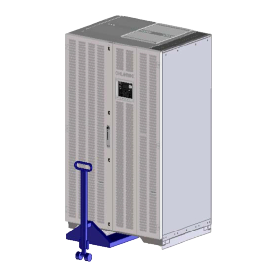
HANDLING The equipment must be kept upright at all times and handled with care. Damage may be caused if subjected to severe impact. The UPS and battery cabinet has been fitted with casters to allow ease of installation near the final location. It is recommended that the UPS and battery cabinets be moved with a pallet jack or fork lift over long distances. -
Page 12: Storage
STORAGE When the UPS is not used within seven days of delivery, please pay special attention to the storage requirements. If the batteries or the equipment is to be stored, they must be kept in a clean, dry environment and away from extremes of temperature. -
Page 13: Preparing For Installation
Chapter PREPARING FOR INSTALLATION ENVIRONMENTAL CONDITIONS The UPS and battery cabinets must be installed vertically, on a level and even surface. The UPS and battery cabinets should be protected from extremes temperatures, water, humidity, and the presence of conductive powder or dust. Do not stack units and do not place any objects on top of the unit. -
Page 14: Chapter 3 - Ups Installation
Chapter UPS INSTALLATION WARNING: Dangerous voltages are present within this unit! There are no user-serviceable parts inside. Any repairs or modifications by the user may result in out-of-warranty repair charges, unsafe electrical conditions, or violation of electrical code. Do not remove the cover. All repairs should be done by qualified service personnel. -
Page 15: Ups Electrical Connections
UPS ELECTRICAL CONNECTIONS In order to gain access to the electrical connections , it will be necessary to Refer to Figure 5 & 6 – Electrical Terminations remove the protection panel located on the front of the UPS behind the front doors. On the UPS and Transformer cabinet, power cables can be brought in from the top or bottom through the access plates and routed through the cable raceway. -
Page 16: Electrical Connections
UPS ELECTRICAL TERMINATIONS Figure 5 – UPS Electrical Terminations Electrical connections Connect the ground wire to the GND terminal. For dual input connect the MAIN AC wires to the INPUT A,B,C, and BY-PASS AC wires to BY-PASS A, B ,C, and N For single input the mains input and bypass will be supplied with jumpers between them. - Page 17 Figure 6 – Input Transformer Cabinet 208/480V...
-
Page 18: Chapter 4- Battery Cabinet Installation
Chapter BATTERY CABINET INSTALLATION BATTERY CONNECTIONS Connections must be carried out only by qualified electricians and in conformity with the applicable safety standards. Both the UPS and battery cabinet are similar in appearance. However the battery cabinet houses the backup power required to provide the energy needed during a power disturbance or outage. - Page 19 Figure 8 – Battery Cabinet Electrical Connections...
- Page 20 Figure 9 – Multiple Cabinet Connections As can be seen in Figure 9 – Multiple Cabinet Connections each cabinet will be connected in parallel. The DC connections between the UPS and battery cabinet must be connected with the most positive of the battery cabinet connected to the positive termination in the UPS.
-
Page 21: Control Panel
Chapter CONTROL PANEL The control panel serves as the interface to the UPS allowing the user to obtain the status of the system and to control as needed. LED’s (Light Emitting Diode) inform the user about three operating parameters of the UPS (1, 2 & 3 below). The LCD (Liquid Crystal Display) will provide detail on messages, alarms, values and operating conditions of the UPS. -
Page 22: Indicators And Buttons
INDICATORS AND BUTTONS ON BATTERY - when this LED is illuminated, the battery supplies the inverter ON BY-PASS - When this LED is illuminated, the load is supplied by the By-pass AC power SUMMARY ALARM - When this LED is solid, the UPS is operating with a fault condition. When blinking, it indicates a warning condition. - Page 23 LEFT ARROW - This button allows the user to scroll left on the LCD RIGHT ARROW - This button allows the user to scroll right on the LCD DOWN ARROW - This button allows the user to scroll down on the LCD UP ARROW - This button allows the user to scroll up on the LCD...
- Page 24 Using the Liquid Crystal Display BY-PASS INPUT INVERTER RECTIFIER INPUT BATTERY LCD Screen – Shows graphical and functional parameters The LCD provides a graphical user interface providing power blocks representing the Rectifier, Battery, Inverter and By-Pass. The power path will be highlighted providing the user with an understanding of which power blocks are active and that which is supplying the critical load.
- Page 25 Menu Structure Main Menu Screen Actual Values Rectifier Alarms Display Settings About By-Pass Rect. No Faults/ Ver. 1.0 UPS Output Battery Language Contrast Input Input No Warnings Chloride Power Protection Values Values Values Values Tel. 1-800- Contrast Message 1 of 3 Displayed Displayed Displayed...
- Page 26 MENUS MAIN MENU The Main Menu screen’s function is to provide the user the selection options for viewing various information about the UPS. Actual Values This is the highest level for menu. To return to previous screen, press ESC button. Parameters displayed are: Actual Values, Inverter Alarms Inverter Alarms, and Rectifier Alarms Display Settings and About.
- Page 27 The Rectifier Input screen displays parameters regarding the RECT. INPUT Main Input. Parameters displayed are: Voltage L1, Voltage L2, Voltage L3, Current L1, Current L2, Current L3, Frequency, Voltage L1 Total Real Power, Real Power L1, Real Power L2, Real Power L3, Total App.
- Page 28 BATTERY The Battery screen displays parameters regarding the inverter’s DC bus. Parameters displayed are: Voltage, Current, Residual Capacity, Expected RUN Time, and Temperature C. Press down or up arrows to view other Voltage entries. Press ESC to exit. Current ACTUAL VALUES The Actual Values screen’s function is to allow access to various parameters at different locations of the UPS.
- Page 29 INVERTER ALARMS The Inverter Alarms information screen displays parameters regarding the alarms. (Shown for No Faults and No Warnings) To return to previous screen, press ESC button. No Faults ... No Warnings ... OR - INVERTER ALARMS The Inverter Alarms Information screen is showing message 1 of 3 and specific information on alarm.
- Page 30 RECTIFIER ALARMS The Rectifier Alarms Information screen is showing message 1 of 3 and specific information on alarm. Using the cursor will display any active alarm messages. To Message 1 of 3 return to previous screen, press ESC button. By-pass Mains Failure MAIN MENU The Main Menu screen’s function is to provide the user the selection options for viewing various information about the UPS.
- Page 31 Display Settings About ... Press to select ABOUT The About screen shows the software revision, manufacturer and support information including the hotline. To return to previous screen, press ESC button. Version 1.0 Chloride Power Protection Tel: 1-800-388-4234 Press to select...
- Page 32 TABLE OF WARNINGS AND FAULTS Warnings Faults Over-temperature inverter Over temperature Converter By-pass mains failure Internal fault Rectifier mains failure Incorrect Power Class (Configuration) Load too high Inverter Contactor Defective Under-voltage VDC Multiple inverter cut off as a result of over current Overload Over-Voltage VDC False By-pass Phase Sequence...
-
Page 33: Operating Modes
OPERATING MODES On-Line Operation CB1, SW1, SW2 and the Battery CB are in the on position and SW3 is in the off position. The loads are supplied by the mains through the inverter. The batteries are charged by the rectifier as necessary. The Inverter filters mains interruptions, disturbances and provides a stable, interference-free supply to the load. -
Page 34: Battery Operation
Battery Operation CB1, SW1, SW2 and the Battery CB are in the on position and SW3 is in the off position. In the event of a mains power failure the load is automatically transferred to the batteries, without interruption. In this mode, the load is supplied entirely by the batteries, via the inverter. - Page 35 Battery Recharge Operation CB1, SW1, SW2 and the Battery CB are in the on position and SW3 is in the off position. The UPS returns automatically to On-Line operation once the mains supply has been restored. The batteries are charged according to the specific battery model provided by the battery manufacturer’s specifications.
- Page 36 By-pass Operation CB1, SW1, SW2 and the Battery CB are in the on position and SW3 is in the off position. In this mode, the load is supplied by the mains through the static switch. This mode of operation does not condition the incoming power. The by-pass further ensures the supply to the load in the event of an overload condition, manual inverter shut off or the unlikely event that the inverter should fail.
- Page 37 Maintenance By-pass Operation CB1, SW1, SW2 and the Battery CB are in the off position and SW3 is in the on position. The load is supplied directly by the mains supply. The Maintenance Bypass is used to supply the load during maintenance operations. CB1 and SW1 can be used to supply power to the UPS for testing or startup without affecting the output.
-
Page 38: Operational Procedures
OPERATIONAL PROCEDURES STARTUP PROCEDURE With main and By-pass disconnects on wall, CB1, SW1-3 and the Battery Cabinet circuit breaker all off, turn on the main disconnect and the By-pass disconnect if present. Turn on SW3 to supply the output with power. Turn on CB1, SW1, SW2 and the Battery Cabinet circuit breaker. -
Page 39: Theory Of Operation
Chapter PARALLEL OPTION The parallel UPS is connected to an AC main power source and contains high current batteries for back up. Therefore safety precautions must be followed to prevent electrical hazards when operating the parallel UPS system. Introduction The CP3150 UPS system can be connected in parallel to increase power capacity or redundancy to the load. Up to 8 units of the same kVA rating may be configured in parallel. - Page 40 Multiple Module Block Diagram Fig 11- Parallel Configuration Planning Special attention must be taken when planning for parallel system installation. The system power cables (input and output) should be the same length. Differences in cable length of 20% are permitted for cables up to 60ft, but for longer cables differences must not exceed 10%.
- Page 41 Installation Input / Output connections When installing a multiple block parallel system, the input and output connections procedures for each module use the same terminals as those for a single UPS. For more information refer to Chapter 3 of Owners Manual. Parallel Communications The individual UPS blocks communicate with each other via a 25-conductor cable.
- Page 42 Parallel communications raceway Figure 13 – Raceway for Parallel Communication Wires Note: When connecting the communication bus, the shield of the communication cable must be grounded to the UPS on each end of the cables.
- Page 43 The Parallel communication terminal blocks (X130 and X140) are located at the upper right front of the UPS, behind the front door and dead plates. Parallel Communication Terminal Blocks Fig 14- Parallel Communication Terminal Blocks Location NOTE: Installation of the parallel kit must be completed by Authorized Technical Personnel.
- Page 44 Chapter CONNECTIVITY Installation of communication card(s) The CP3000 series can be equipped with a variety of connectivity options. Five interface slots have been designed to allow installation of the AS400 card, LIFE 2000 card, R.A.U. card (Remote Alarm Unit), RS232 card and Manage UPS Net adapter card. These interface slots are located behind the front panel located in the middle right section.
- Page 45 Recommended Communication configuration Shown in Figure 16 – Communication Card Configuration are the recommendations of those communication options and were to insert them. Remote Alarm Unit LIFE 2000 ManageUPS Mop UPS Card or Modem AS400 Card Net Card RS232 Card Industrial Card Contact...
- Page 46 RAU/RLY/DVR CARD This card allows connection to the Remote Alarm Unit option. It also can be used to drive the Industrial Contact Card as seen in Figure 17 – RAU (Remote Alarm Unit) or Relay Card or Driver Card. The voltage-free contacts are rated at 30V .5A max. Figure 17 - RAU (Remote Alarm Unit) or Relay or Driver Card The RAU/RLY/DVR PCB terminal layout is as follows: •...
- Page 47 AS400 CARD The AS400 (Relay) card is equipped with a “D”-type female 9-pin connector comprising voltage-free contacts and conforming to the requirements of IBM AS/400 and other computing systems. Figure 18 - AS400 (Relay) card The interface communication pin layout is as follows •...
- Page 48 RS232 CARD The male 9-pos. SUB-D connector contains the RS 232 signals. Figure 19 - RS232 Card The interface COM is isolated from all power circuits. • Pin 5 GND This connection point serves as a reference for all signals. •...
- Page 49 ManageUPS NET CARD ManageUPS (formerly known as the SNMP adapter) includes a complete package allowing CP3000 SERIES to be monitored and controlled over a network using TCP/IP protocol. The adapter allows: • UPS monitoring from an NMS station using SNMP •...
- Page 50 LIFE2000 MODEM CARD This option provides remote monitoring of the UPS, via a dedicated analog telephone line, to ensure maximum reliability for the duration of its operational life. The UPS automatically telephones the service center at predefined intervals, to provide detailed information, which is analyzed in order to predict any short-term failures.
- Page 51 INDUSTRIAL CONTACT CARD Figure - 22 Industrial Contact Card and Bracket The contacts are rated at 120VAC, 2A.
- Page 52 REMOTE EQUIPMENT POWER OFF Figure - 24 Remote Equipment Power Off (REPO) To wire the external EPO circuit, connect a normally closed (N/C) emergency switch, which opens when activated and is held open mechanically when operated. Make sure switch is de-activated (closed) before connecting to the outer terminals of the EPO terminal block (REPO Hi and REPO Low).
- Page 53 CHLORIDE POWER PROTECTION Customer Service Center is fully equipped to deal with such batteries, in accordance with the Law and with the greatest respect for the environment.
- Page 54 STORAGE For extended storage at ambient temperature < 77°F, the batteries should be charged for 5 hours once every 4 months; at higher storage temperatures, it is advised that this period be reduced to two months. Make sure the Power Control Unit Breaker is in the OFF position before continuing. Follow the electrical installation procedure in Chapter 3.
- Page 55 Appendi x INSTALLATION TABLES AND ILLUSTRATIONS The information in the appendix will provide you with the necessary data to install the UPS and Battery Cabinet. Following is a list of tables and drawings. • Table 1 - Input/ Output Ratings & External Wiring Recommendations •...
- Page 56 Table 1 - Input/ Output Ratings & External Wiring Recommendations Model CP3150/150kVA/125kVA Details Units Rating for 60Hz Terminal Voltage Input/ Output current, Conductor size & Circuit Function Configurations Breaker rating kW@ .9PF Max input current (3Ph, 1 gnd) A AC Nom input current (3Ph, 1 gnd) A AC AWG or...
- Page 57 Table 1 Continued - Input/ Output Ratings & External Wiring Recommendations Nom output current ( 3Ph, 1 Neutral, 1 gnd) A AC AWG or 208V-208Y/120 Minimum conductor size (number per phase) kcmil 250(2) 350(2) 3 Pole, A Recommended output circuit breaker ratings Nom output current ( 3Ph, 1 Neutral, 1 gnd) A AC AWG or...
- Page 58 Table 2 – Input/Output and Battery Cabinet Wire Terminations for Single Input Power Cable Terminations - Single Input Tightening Wire Size of Clamp Torque Type Termination Screw Termination Terminal In.-lbs 6AWG-350MCM (2) 3/8 Hex AC Input 6AWG-350MCM (2) 3/8 Hex 6AWG-350MCM (2) 3/8 Hex 1/2 Hex...
- Page 59 Table 3 – Input/Output and Battery Cabinet Wire Terminations for Dual Input Power Cable Terminations - Dual Input Tightening Wire Size of Clamp Torque Type Termination Terminal Termination In.-lbs Screw 3/0-250MCM (2) 5/16 Hex AC Input to 3/0-250MCM (2) 5/16 Hex UPS Rectifier 3/0-250MCM (2) 5/16 Hex...
- Page 60 Table 4 – Full Load Heat Rejection Full Load Heat Rejection (BTU/Hr) Configuration Model CP3150-150kVA 56,931 45,556 34,670 CP3150-125kVA 47,442 37,963 28,892 Table 5 – Weight Specifications Weight Specifications CP3150-150kVA/125kVA Weight (lbs) Floor Loading (lbs) 480in/480out 2564 4 at 641 480in/208out 3675 4 at 919...
- Page 62 Illustration B...
- Page 63 BATTERY CABINET TOP DIMENSIONS Illustration C...
- Page 64 For a number of years CHLORIDE POWER PROTECTION has been committed to a policy of Total Quality and today devotes a great deal of resources and energy to providing the best possible after-sales service. Therefore, we value any suggestion you might make and consider it an inspiration for our continued improvement.
Need help?
Do you have a question about the CP3150 Series and is the answer not in the manual?
Questions and answers