Advertisement
Quick Links
1.-
INTRODUCTION.
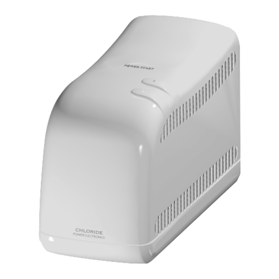
"POWER START" is a single phase line interactive UPS with booster. It is fully
microprocessor controlled with computer communication capabilities.
The power rates are 250VA - 400VA - 600VA for 230V 50Hz and 250VA - 400VA - 600VA
for 115V 60Hz all of them with cos ϕ = 0.6 (power factor).
It has automatic voltage regulation in two steeps, central and boost. The unit corrects the
low input voltage with the boost step.
The inverter is "PUSH-PULL" with "NULL", based on MOSFET technology. The waveform is
regulated pseudosine when the unit operates on-battery.
The charger is based on a lineal regulator with full rectifier bridge.
IN
The boards' code is 500152.XXX ( these codes can be changed in the future ).
REVISION NOTE : If any repair or modification affecting the revision of the equipment is
carried out, then this situation should be reflected on the identification sticker.
942088.001 - 24/09/98
TECHNICAL MANUAL
TABLE OF CONTENTS
1.- INTRODUCTION
2.- EXTERNALS COMPONENTS
3.- BASIC OPERATION
4.- MAINTENANCE PROCEDURE
5.- ELECTRONIC BOARD OPERATION 7
BOOST
BATTERY
942088.001
OUT
AC
DC
CONVERTER
1
2
4
6
1
Advertisement

Related Manuals for Chloride Power Star


Summary of Contents for Chloride Power Star
- Page 1 TECHNICAL MANUAL 942088.001 TABLE OF CONTENTS 1.- INTRODUCTION 2.- EXTERNALS COMPONENTS 3.- BASIC OPERATION 4.- MAINTENANCE PROCEDURE 5.- ELECTRONIC BOARD OPERATION 7 INTRODUCTION. “POWER START” is a single phase line interactive UPS with booster. It is fully microprocessor controlled with computer communication capabilities. The power rates are 250VA - 400VA - 600VA for 230V 50Hz and 250VA - 400VA - 600VA for 115V 60Hz all of them with cos ϕ...
- Page 2 TECHNICAL MANUAL 942088.001 EXTERNALS COMPONENTS. 2.1 - Two output leads ( IEC320 ). 2.2 - Mains connector ( IEC320 ). 2.3 - Fuseholder 250Vac. 5x20mm. Time-lag T. High breaking capacity. 250VA 230V 400VA 230V 600VA 230V 250VA 115V 400VA 115V 600VA 115V 2.4 - Communication connector ( RJ11 6/6 ) Description...
- Page 3 TECHNICAL MANUAL 942088.001 2.5.1 - RS232 connector (RJ11 type) with the following signals: Description Reserved ( +5V @. 10mA ) TDX, ( Transmits date to the PC ) Ground RDX, ( Receives data from the PC ) Pin 1 is reserved for special purposes. Signals 2 and 4 are “RS232” levels. This connector is used for the serial communication with the PC using the User and Technical Software.
-
Page 4: Basic Operation
TECHNICAL MANUAL 942088.001 BASIC OPERATION. “POWER START” has no ON/OFF switch, when the mains voltage is present the unit automatically starts up. The UPS can turn its output off by the “TIME PROGRAMMER” or by “AUTO-OFF”. During the start up, the UPS does an “AUTOTEST”, if the battery, internal circuits and the mains are correct, it will connect the relays supplying voltage to the output. - Page 5 TECHNICAL MANUAL 942088.001 3.- TIMER switch off: The UPS switch off will be carried out at the time and the date recorded. The UPS will remain in “STAND-BY” mode. The UPS will start up with the “TIMER” switch or with “START UP” command if the mains is present. 4.- Stop due to protection: The UPS has one protective feature that could force it to stop ( Short circuit in the Output).
-
Page 6: Maintenance Procedure
Replace the battery with the same type as originally installed ( Sealed lead acid, maintenance free 12V - 7Ah), supplied by the UPS manufacturer (Chloride Part. No.580085.000) with a polarised connector. The battery contains toxic materials. Dispose of battery properly (must be recycled). - Page 7 TECHNICAL MANUAL 942088.001 WIRES SOLDER TO THE POWER START BOARDS BLACK 4 WHITE WHITE GRAY BROWN BROWN (NEG BAT) RED ST1 (Lin) GREEN YELLOW BLUE BLACK BLACK GRAY 4 BLUE 4 RED (+BAT) (N,C,D) ELECTRONIC BOARD OPERATION 5.1 Measurements circuits. 5.1.1 Battery Voltage: R8 and R9 provide to the microprocessor PD2 pin (analogy input) an image of the battery voltage.
- Page 8 TECHNICAL MANUAL 942088.001 5.2 Charger block and internal mains The L and M terminals are connected to the transformer winding charger. This signal is rectified with D4, D3, T4 and T5. IC5 regulates the charger voltage in function of the voltage of the ADJ pin.
- Page 9 TECHNICAL MANUAL 942088.001 Boards Signals. Mains voltage measurement ( 3.- Zero crossing IRQ ) ( 2.- Mains voltage ) ( 1.- Mains phase ) Output voltage measurement ( 2.- On mains ) ( 1.- On inverter ) Output voltage waveform ( 2.- On mains ) ( 1.- On inverter ) 942088.001 - 24/09/98...
Need help?
Do you have a question about the Power Star and is the answer not in the manual?
Questions and answers