Table of Contents
Advertisement
Quick Links
User Manual
Conference Discussion System
CU 4005/4010
DM 4000/4100/4400
CM 4000/4100/4400
MU 4040
HM 4042/4047
MC 4000
SW 4210/4211/4220
Danish Interpretation Systems
with installation guide
Series Central Units
Series Delegate Units
Series Chairman Units
Microphone Unit
Hand Microphones
Microphone Control
System Control Software
DIS
Advertisement
Table of Contents

Subscribe to Our Youtube Channel
Related Manuals for DIS CDS 4000


Summary of Contents for DIS CDS 4000
-
Page 1: User Manual
User Manual with installation guide Conference Discussion System CU 4005/4010 Series Central Units DM 4000/4100/4400 Series Delegate Units CM 4000/4100/4400 Series Chairman Units MU 4040 Microphone Unit HM 4042/4047 Hand Microphones MC 4000 Microphone Control SW 4210/4211/4220 System Control Software Danish Interpretation Systems... -
Page 2: Table Of Contents
CDS 4000 LIST OF CONTENTS List of Contents Front panel controls ........14 List of Contents ............. 2 Rear panel connectors ........15 Installation instructions......... 16 Document version..........4 Where to place ..........16 Ventilators............16 Warning ..............5 Removing 19"-brackets........16 How to open the unit ........16 For all customers .......... - Page 3 CDS 4000 LIST OF CONTENTS Standard Operations mode ......27 Line in (XLR3 female) / Microphone output System Settings Operation mode....29 (XLR3 male) ..........43 Test Operation mode ........29 Microphone Chain connector (D15 female).43 Program Operation mode ......30 Control link connector (D9 female / D9 male)43 Error detection feature.........
-
Page 4: Document Version
02-06-2003 Version: Name: CDS4000E.DOC Copyright© 1999-2003 DIS, Danish Interpretation Systems A/S No part of this publication may be reproduced or utilised in any form or by any means without permission in writing from the publisher. Manual no. 4479, Printed in Denmark, 02/03... -
Page 5: Warning
CDS 4000 WARNING Warning Brown: Live For all customers The colours of the wires in the mains lead of this The equipment has been tested and found to apparatus may not correspond with the coloured comply with the limits of the CE test. These limits markings identifying the terminals in your plug, so are designed to provide reasonable protection please proceed as follows:... -
Page 6: Important
Do not place the unit on a surface from DIS. We recommend you to use this system (rugs, blankets, etc.) that may block the ventilation for long term protection and care. -
Page 7: Description Of The System
• Custom-made models available connection cable themselves. Basically the CDS 4000 system can be a fully By using genuine DIS extension cables, installation automatic system with up to 100 microphones when can never be made incorrectly. used with one CU4010 or up to 10 x 100 = 1000... -
Page 8: System Components
CDS 4000 DESCRIPTION OF THE SYSTEM System components All units, which are part of the CDS 4000 system, are listed below. Model Description CU4005 Central Unit. Automatic and FIFO operation modes, 50 microphone units connected as maximum. Interconnection of up to ten CU4005/CU4010 units for of up to 500/1000 microphones. Manual operation with MC4000 and computer control with optional RS4232 module built-in. -
Page 9: Modes Of Operation
This They will all be placed in a request queue with unique DIS feature is named DVR, Dynamic the first in the queue flashing with the green Voice Response. -
Page 10: Operation
CDS 4000 OPERATION Operation CU4005, CU4010 The CU4005/CU4010 contains the power supply for the system. The mains input can be selected to a Description wide range of AC-voltages making world-wide use of the system possible. An electronically balanced line is provided for tape recorders, buffer amplifiers, etc. -
Page 11: Cu4010 Set-Up With External Mixer
CDS 4000 OPERATION In this situation the level of the DM/CM4000 units and the level of the wireless microphone connected connected to the Delegate Microphones connector to the Input connector is adjusted with the Input is adjusted with the Microphone Volume control, Volume control. -
Page 12: Exit
CDS 4000 OPERATION Note: buttons < or > the markers < > can be moved When the CU4005/CU4010 has the RS4232 respectively left and right. module built-in, this unit will count as two units. The four choices in the Main menu are: After successful set-up time the LCD-display of the •... -
Page 13: Status
CDS 4000 OPERATION one by one in between new test cycles, until no If a fatal fault is present in a chain, and the central fault is reported. In this way it is possible to locate unit is incapable of recording the number of a bad unit in the chain. -
Page 14: Display, Slaves
CDS 4000 OPERATION are made at the MC or PC. The display of the Display, slaves master will then look like this: The LCD-display of the slaves will always look like this: Total:125 PC/MC Menu: Slave:1 Chairmen:1 Menu: MASTER Vol: Inp=off Mic=-20 SLAVE Chain1:24 Chain2:0 This indicates that an MC4000 Microphone... -
Page 15: Rear Panel Connectors
CDS 4000 OPERATION Enter < and > This button is used to enter the menus and select These buttons are used to step the markers < > a chosen value. left and right respectively for each push. The markers < > around exit show the function LCD Display which can now be selected with the ENTER Indicates the setting of the system. -
Page 16: Installation Instructions
CDS 4000 OPERATION has become overheated, turn Off the power, remove things that prevent proper ventilation and wait until it has cooled down. Then turn On again. CAUTION: Do not remove rubber pads in bottom, as they are needed for proper ventilation. The CU4005/CU4010 can also be installed in a 19"-rack using the holes in the brackets on each Input... -
Page 17: Internal Settings
CDS 4000 OPERATION connected units, then you should approach your Open the unit (see section “How to open the dealer or order service by qualified personnel. unit). The voltage selector is placed in the right side of Internal settings the unit close to the front. Turn the selector with a coin and Select the voltage equal to or within +/- 10% to one of the following voltages shown on Changing the voltage settings... -
Page 18: Manual Mode
CDS 4000 OPERATION Manual Mode CM4000 Series Chairman Units Pressing the ON/OFF button will place the Pressing the ON/OFF button (1) will always turn microphone in the request queue of the MC4000. the microphone on or off depending on the current This is confirmed by green light in the request lamp state. -
Page 19: Dm/Cm4410/4420 Delegate & Chairman Units
CDS 4000 OPERATION DM/CM4410/4420 Delegate & Chairman Units DM 4400 Series Units The 4400 series microphone operates exactly like the 4000 series microphone described in the previous section. All delegate and chairman functions described are the same. Set-up Whereas the daisy chain cable connector on the 4000 &... -
Page 20: Dm 4100 Series Delegate Units
• Electret condenser microphones with MS or CU, you should check the serial number and built-in FET and positive supply such as call DIS A/S for further information. the DIS microphones GM40xx, SM 4025 and SM 4026. DM 4100 Series Delegate Units •... -
Page 21: Cm 4100 Chairman Units
CDS 4000 OPERATION CM 4100 Chairman Units The function of this unit is similar to the description of the CM4000 regarding the normal auto/man. mode and the DM 4100 regarding the 4100 series features. The three buttons on the control box selects one of the operation modes. - Page 22 CDS 4000 OPERATION switched on by voice, it is not possible to force of the microphone unit. Pink noise is then it off remotely. produced from the LS4100. • If CU4005/CU4010 is used as central unit w/o Place the loudspeaker in front of the MC4000, you need to switch off any units being microphone arm in such a way that the on, before selecting the mode Voice Activated.
-
Page 23: Dynamic Voice Response (Dvr)
CDS 4000 OPERATION microphone unit, as this turns the built-in 4. Headphone Connector loudspeaker ON and gives a faulty noise level to This mini-jack socket allows for connection of a the mic. headphone or the LS4100 Loudspeaker. After this adjustment the output level of the microphone units is the same as that of the standard DM/CM4000 units. -
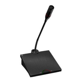
Page 24: Mu4040 Microphone Unit
CDS 4000 OPERATION MU4040 Microphone Unit The MU4040 is set-up similar to the other DM/CM4000 Series Units. The MU4040 operates in the same modes as described for the DM/CM4000 Series Units. The MU4040 is provided with a fixed cable for daisy chain connection to the back of the previous unit, a connector for connection for the next MU4040 unit and a HD 15S connector. -
Page 25: Hm4042/Hm4047 Hand Microphones
CDS 4000 OPERATION HM4042/HM4047 Hand Microphones 2. 1. HM4047 shown with cable HM4042 shown without cable Description Controls The HM4042/HM4047 Hand Microphone is 1. If the HM4042/HM4047 Hand Microphone is designed for use with the DM/CM 4121P Series connected to the HD15S connector, the function Units and the MU4040 unit. -
Page 26: System Enhancement
CDS 4000 SYSTEM ENHANCEMENT System enhancement MC4000 Microphone Control Description MC4000 features: • TEN KEY PAD CONTROL WITH DISPLAY of any microphone unit switched to any operating status. • SINGLE BUTTON CONTROL of microphone units displayed in Speak, Request, Preselect or Last Speaker mode. -
Page 27: Location Of Controls
CDS 4000 SYSTEM ENHANCEMENT Location of controls Start-up Standard Operations mode The MC4000 Microphone Control unit is powered Upon completion of the initialization sequence the from the CU4005/CU4010 Central Unit via the MC4000 enters Standard Operations mode. Control Link Bus, and the MC4000 unit will power D1 displays the Master CU mode, which may be on, when one or more of the CU4005/CU4010 units one of the following AUTO (Automatic mode),... - Page 28 CDS 4000 SYSTEM ENHANCEMENT changed using the B2 buttons respectively to request queue will not be visible. The preselected decrease and increase the Volume in steps of 1 dB. microphones are distinguished from microphones in the request queue by the letter 'P' preceding the D4 displays the current setting of the Microphone microphone number (e.g.
-
Page 29: System Settings Operation Mode
CDS 4000 SYSTEM ENHANCEMENT Pressing the SET MODE (B1) button will change MAN indicate the mode of the CU4005/CU4010 as the MC4000 mode of operation from normal mode described in the CU4005/CU4010 section of this to system settings mode. manual, whereas TEST and PROG indicate modes of operation applying solely to the MC4000 System Settings Operation mode microphone controller. -
Page 30: Program Operation Mode
CDS 4000 SYSTEM ENHANCEMENT currently in speak. DS5 displays the text "RUN" chain 1 has number 901. In order to ease the remote indicating that the BS5 button is now used to start control of the microphone system it is possible for an automatic test of the microphones. -
Page 31: Error Detection Feature
CDS 4000 SYSTEM ENHANCEMENT numbers in DR2-DR5 refer to the logical microphone numbers (the led LS6 is lit). The mode microphone numbers, and that pressing the BR1 of sorting is toggled when the BS6 button is button will scroll the view of the list up one pressed. -
Page 32: Setting Up A Large System
CDS 4000 SYSTEM ENHANCEMENT quickly identify the error and correct it. This error pressed. message will keep displaying until any key is Setting up a large system The central units are interconnected with the CU4005. The CU4010 allows connection of 100 control link cables in the D9-connectors NEXT microphone units, but please note that each chain CU4005/CU4010 and PREVIOUS... -
Page 33: Sw4200/4210/4220 System Control Software
CDS 4000 SYSTEM ENHANCEMENT MC4000 units are connected to one central unit, a system. An RS4232 module shall then be built-in to separate power supply is needed. any one of the central units. A suitable program that can communicate with the system is needed. A Up to four personal computers or other equipment maximum of two RS4232 modules are allowed in with RS232 or RS422 communication ports can be... -
Page 34: Installation Guide
The microphone units comes in two versions: cable with 26-pin connectors used instead of P=Portable and F=Flush mounted. The flush the special DIS round cables with D15- mounted units are used for permanent fixed connectors used for the P-type. Female 26-pin installations. -
Page 35: Ribbon Cables
CDS 4000 INSTALLATION GUIDE spring lock on the front plate profile will not Ribbon Cables function correctly. Please refer to marker inside • Use only 13x2 (13 pairs) twisted ribbon cable the C-profile. type AWG 28 or equal and ribbon female •... -
Page 36: Control Link Cables
NOTE cable. Use only DIS round cable in such cases. Conversion between round cables and ribbon • cables can be obtained by using the standard DIS... -
Page 37: Mc4000 Microphone Controller
The maximum number of MC4000 units in a recommended to counter sink the screws in the system is two. front and to use black counter sunken screws. Can be ordered from DIS. • The cable length between any CU4005/CU4010 and an MC4000 must not exceed 50 m using 4x2x0,25 mm cable. -
Page 38: Cu4005/Cu4010 Central Units
CDS 4000 INSTALLATION GUIDE • RS422 cables can be up to 1000 m. Voice Activated Microphones • For RS422 a flexible cable of 5x2x0,25 mm The DM/CM41xx units draw more current, and (min. 5 pairs) with screen is recommended. they also function a little different. Because of the higher current consumption fewer units can be used in one chain and somewhat shorter cable lengths CU4005/CU4010 Central Units... -
Page 39: Accessories
2696 between individual microphone units. However the ribbon- to round cable. installation guide provided in this manual must be followed. The cable is special made by DIS only. CC4003, Cable Converter 4686 Strip. Cable 0,5m complete Extension cables can be delivered in accordance... -
Page 40: Specifications
CDS 4000 SPECIFICATIONS Specifications Electrical Balanced CU4005/CU4010 Central Unit Input level: Adjustable Microphone capacity: 100 mV-1,55 V CU4005 50 units in one chain Max. input level: +20 dBm (8V) CU4010 100 units in two chains Connector: XLR3S Frequency response: Microphone Output: Mic. -
Page 41: General
CDS 4000 SPECIFICATIONS General Power requirement Storage temperature CU4005/10 110/130/150/220/240/260 V AC -20 Deg C. to 60 Deg C. (10 to 80% humidity) 50/60 Hz DM/CM4000, MC4000 Weight Supplied from CU4005/CU4010 CU4005 8.9 kg MC4000 +12V - +15V/12VA CU4010 10.6 kg Power consumption MC4000 1.3 kg... -
Page 42: Dimensions
CDS 4000 SPECIFICATIONS Dimensions Note: All dimensions are in millimetres. DM/CM4410 P Delegate/Chairman Unit DM/CM4420 P Delegate/Chairman Unit W * H * D, (mm): 150 * 400 * 171 mm W * H * D, (mm): 150 * 73 * 171 mm Note: Measured with vertical gooseneck. -
Page 43: Pin Assignments
In phase signal or 2 x 0,25 mm shielded. Out phase signal Each in/output is electronically balanced Microphone Chain connector (D15 female) Signal Cable type +MIC DIS type #2029 only. +15V +LS (50V) Data in Latch +15V -MIC +15V (analogue) -15V... -
Page 44: Rs232 Connector
CDS 4000 SPECIFICATIONS RS232 connector Signal Cable type DIS type: #5611, D9S – D9S, 5m pre- terminated 4 x 0,14 mm shielded RS422 connector Signal Cable type +CTS DIS type: +RxD 4 x 2 x 0,25 mm shielded +TxD +RTS... -
Page 45: Dm/Cm4121 & Mu4040
CDS 4000 SPECIFICATIONS DM/CM4121 & MU4040 Input (HD15S) Signal Cable type - Loudspeaker output DIS type: #2029 Speak LED Request LED according to the specific ON/OFF switch input installation. Delegate OFF switch DM/CM 4121: Voice active output MU4040: +Relay + Loudspeaker output (4 ohm) -
Page 46: Appendix 1, External Control Of The Cu 4005 / Cu 4010
CDS 4000 RS232 PROTOCOL Appendix 1, External Control of the CU 4005 / CU 4010 General Data is sent using a rate of 9600 baud, 8 bits, No _ (underscore) is used in this paper to identify the Parity and 1 stop bit. The RTS/CTS handshake space character. -
Page 47: Maximum Number Of Delegates Speaking
CDS 4000 RS232 PROTOCOL <CHAIRMAN1 CHAIN> holds the number of the Volume Control Chain (1-2) to which the first chairman microphone "!V<MIC VOLUME><INPUT is connected. VOLUME><CHKSUM>" <CHAIRMAN1 MIC> holds the number of the This message is sent, when one of the volume Chairman microphone in the Chain (1-50). -
Page 48: Microphone In Request
CDS 4000 RS232 PROTOCOL This message is sent when a microphone is put in download message. The bytes <POSmsb> and request. <POSlsb> identifies the position in the conversion table where the update was applied. Microphone in Request Test status message "!r<CU><CHAIN><MIC><CHKSUM>"... -
Page 49: Serial Receive Overflow
CDS 4000 RS232 PROTOCOL occur if the external equipment is not honouring the Serial Receive overflow CTS/RTS hardware handshake signals. An "!F<CR>" overflow will result in the loss of one or more messages to the interface card, and these messages This message is sent from the interface card if an will have to be repeated. -
Page 50: Data To The Rs4232 Card
CDS 4000 RS232 PROTOCOL Data to the RS4232 Card Sending this message to the interface card has the System status request messages same effect as pressing a Delegate Off button on a chairman microphone. In Manual and Automatic The external equipment can request the status of mode all delegate microphones will be turned off - the various system variables. -
Page 51: Dm / Cm 4100 Series Voice Activated Microphone Units
CDS 4000 RS232 PROTOCOL number LOG2 and so forth. 10 consecutive the same logical number - the MC4000 software physical numbers are always updated upon enforces the basic rule that all logical numbers in reception of a download message. Note observe the the conversion table have to be different.
Need help?
Do you have a question about the CDS 4000 and is the answer not in the manual?
Questions and answers