Table of Contents
Advertisement
Advertisement
Table of Contents

Related Manuals for Servend CEV SERIES


Summary of Contents for Servend CEV SERIES
- Page 1 CEV SERIES Beverage Dispensers Installation, Use & Care Manual This manual is updated as new information and models are released. Visit our website for the latest manual. www.manitowocfsg.com Leader in Ice & Beverage Dispensers Part Number 020004000 10/13...
- Page 2 Safety Notices Read These Before Proceeding: As you work on Manitowoc equipment, be sure to pay close attention to the safety notices in this manual. ! Caution Disregarding the notices may lead to serious injury and/ Proper installation, care and maintenance are or damage to the equipment.
- Page 3 Table of Contents (continued) Section 1 General Information Read This Manual ..........Unit Inspection .
-
Page 4: Table Of Contents
Table of Contents (continued) Section 3 Operation Component Identification ......... . . Sequence of Operation . -
Page 5: Read This Manual
Section 1 General Information Read This Manual Model Numbers Manitowoc Beverage Systems (MBS) developed this This manual covers the following models: manual as a reference guide for the owner/operator and installer of this equipment. Please read this manual Beverage Dispensers before installation or operation of the machine. -
Page 6: Serial Number Location
General Information Section 1 Serial Number Location This number is required when requesting information from your local distributor. The serial number is listed on the SERIAL NUMBER DECAL affixed to the dispenser. Label Serial Number Location Warranty Information Consult your local MBS Distributor for terms and conditions of your warranty. -
Page 7: General System Overview
Failure to follow these installation guidelines may installer. Contact your Manitowoc Beverage Equipment affect warranty coverage. Service Agent or call Manitowoc Beverage Equipment for information regarding start-up services. Typical CEV Series Internal Carbonation Beverage Dispensing System SYRUP Syrup Pump CARBONATED WATER 1800... -
Page 8: Pre-Installation Checklist
Installation Instructions Section 2 Pre-installation Checklist When installing any system, first make sure the major components are available. Generally the major components necessary for an installation are: Pre-mix System: Post Mix System: regulator set regulator set Product connectors for Figal tank Beverage dispenser Gas connectors for Figal tank Beverage tubing... -
Page 9: Installation Instructions
Section 2 Installation Instructions Bulk Syrup System also: Also consider the location of the following items before installation: Syrup connectors for Bulk tank Water line Gas connectors for Bulk tank Drain Bulk syrup tanks Power outlet Double Check: Heating and air conditioning ducts Do you have enough space to install the dispenser or a dispenser and top mounted cuber? -
Page 10: Selecting Locations
Installation Instructions Section 2 Selecting Locations Island Mount The CEV may be island-mounted or installed on a front or rear counter. Locate the CEV so the following requirements are satisfied: CEV is for indoor use only and must NOT be placed in an area where a water jet or similar high pressure sprayer could be used. - Page 11 Section 2 Installation Instructions Counter Electric Dispenser Dimensions * C = Valve height using Flomatic Valves. MODEL CEV-30 29.88" 20.50" 11.76" 4.44" 25.75" 17.00" 17.50" (75.9 cm) (52.7 cm) (29.8 cm) (11.3 cm) (65.4 cm) (43.1 cm) (44.4 cm) CEV-40 29.88"...
-
Page 12: Footprints
Installation Instructions Section 2 Footprints CEV30 FOOTPRINT ! Caution Cutting the countertop may decrease its strength. Counter should be braced to support the dispenser countertop weight plus ice storage capacity and weight of icemaker, if applicable. Part Number 020004000 10/13... -
Page 13: Cev40 Footprint
Section 2 Installation Instructions CEV40 FOOTPRINT ! Caution Cutting the countertop may decrease its strength. Counter should be braced to support the dispenser countertop weight plus ice storage capacity and weight of icemaker, if applicable. Part Number 020004000 10/13... -
Page 14: Location
Installation Instructions Section 2 Location Avoid placing the dispenser near heat sources such as radiators, ovens, refrigeration equipment and direct sunlight. Warning Carbon Dioxide (CO ) displaces oxygen. Exposure to a high concentration of CO gas causes tremors, which are followed rapidly by loss of consciousness and suffocation. -
Page 15: Electrical
The plug must be plugged into an VOLTAGE appropriate outlet that is properly installed and grounded The standard voltage for CEV Series dispensers is in accordance with all local codes and ordinances. 120VAC-60Hz 1 Ph. A power cord is provided with 120VAC-60Hz models only. - Page 16 Installation Instructions Section 2 Warning When using electric appliances, basic precautions should always be followed, including the following: a. Read all the instructions before using the appliance. b. To reduce the risk of injury, close supervision is necessary when an appliance is used near children.
-
Page 17: Unit Installation
Section 2 Installation Instructions Unit Installation COUNTER SEALING FILLING THE WATER TANK In order for all CEV units to comply with NSF requirements Warning within the United States, the CEV base must be sealed to CEV must be electrically grounded to avoid possible fatal the countertop unless the optional 4”... -
Page 18: Refrigeration System Start
Installation Instructions Section 2 REFRIGERATION SYSTEM START The carbonator pump should be located within 6 feet of a 1/2 inch water source. A minimum 3/8 inch ID water A. Assure the water tank is properly filled. The CEV line must be used. Before connection the water source will not operate without water in the tank. -
Page 19: Carbonator Tank Purge Tube Routing
Section 2 Installation Instructions CARBONATOR TANK PURGE TUBE ROUTING 1. During installation of unit the carbonator tank purge tube (A) must be properly routed to a drain. Once the splash panel has been removed from unit 3. The carbonator tank purge tube (A) can be routed remove twist tie (B) that holds carbonator tank purge down through the counter top that unit has been tube. -
Page 20: Premix Pressures
Installation Instructions Section 2 CONNECTING WATER & SYRUP SUPPLY LINE(S) 3. Open carbonator tank pressure relief valve. (Yellow arm should be in the upright position). Water Lines 4. Turn water supply on and fill the carbonator tank until CEVi (Internal Carbonator) water can be seen coming out the pressure relief valve. -
Page 21: Plumbing Diagrams
Section 2 Installation Instructions PLUMBING DIAGRAMS NOTE: A check valve must be installed in the water supply line 3 feet from the noncarbonated water connection “PW”. Contact factory if not installed. CEV-30e & CEV-30i 5 Valve Diagram CEV-30e & CEV-30i 6Valve Diagram 2-15 Part Number 020004000 10/13... - Page 22 Installation Instructions Section 2 CEV-40e & CEV-40i 8Valve Diagram CEV-30j 4,5 & 6 Valve Diagram 2-16 Part Number 020004000 10/13...
-
Page 23: Carbonated/Non-Carbonated Conversion Instructions
Section 2 Installation Instructions CARBONATED/NON-CARBONATED CONVERSION INSTRUCTIONS CEV BAG-IN-BOX (BIB) START-UP INSTALL LABELS All lines should be properly flushed and sanitized before Install flavor labels (some labels are provided with the CEV) starting the CEV. See Sanitizing Instructions on the dispensing valve covers. 1. -
Page 24: Ada Key Pads
Installation Instructions Section 2 ADA KEY PADS These instructions are for installations with this option. Drain Pan & ADA Touch Pad Box 1. Remove power from the unit. 6. Attach the drain pan to the unit. Splash Panel Removal 7. Center the ADA Key Pad Box with the unit in front of the drain pan and secure into place. - Page 25 Section 2 Installation Instructions ADA Key Pad Matrix Finish Installation 4 Valve Dispensers 9. Put the splash panel and merchandiser back onto the unit and reinstall the screws that hold them in place. 10. Restore power to the unit. Clean Up Clean up all work areas.
-
Page 26: Operation
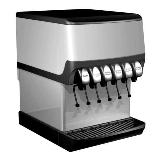
Section 3 Operation Component Identification Merchandiser Soda Valves Key Switch Splash Panel Drainpan Grid Drainpan Sequence of Operation This section gives the Counter-Electric Dispenser description, 2. Make sure all items are present and in good condition. theory of operation, and service data for the 6 and 8 flavor Loose shipped items in the carton include the drain kit Post Mix Dispensers (hereafter referred to as CEV.) parts and the instructions. -
Page 27: Beverage Valves
Operation Section 3 BEVERAGE VALVES inlet Post-mix beverage valves are designed to precisely meter the 120 psi max Pressure Relief flow of both water and syrup to obtain the proper mixing ratio. The syrup and soda water components of the post-mix beverage are mixed as they leave the beverage valve. -
Page 28: Carbonated Water
Section 3 Operation CEVj BACK ROOM PACKAGE The CEV-30j is a 4, 5 or 6-valve unit and is capable of Booster System dispensing non-carbonated drinks only. A CO cylinder (If Required) delivers carbon dioxide (CO ) gas through adjustable CO Water Regulator From Water Supply regulators to the syrup/juice BIB pump. -
Page 29: Figal System
Operation Section 3 7. Primary pressure regulator - Lowers the CO The stainless steel Figal beverage tanks are easy to pressure, to 100 psi (689.48 KPa), so the CO store and connect. There are several items to remember will be at the proper pressure to enter the carbonator when using the Figal tanks: regulator. -
Page 30: Operation Checks And Adjustments
Section 3 Operation Operation Checks and Adjustments Element Function Carbonator Fill Timing Jumper • Carbonator tank fill timing ELECTRONIC ICE AND & CARBONATION CONTROL provides pump failure (Not used on External Carb. or Juice protection in the event of water Units) Element Function... -
Page 31: Maintenance
Section 4 Maintenance Cleaning DAILY CLEANING Clean the exterior and drain pan: All cleaning must meet your local health department 1. Turn off the key switch located on either right or left regulations. The following cleaning instructions are side of the unit. provided as a guide. -
Page 32: Cleaning Checklist
Maintenance Section 4 CLEANING CHECKLIST Sanitizing • Check CO supply. If CO supply is low, an arrow on BEVERAGE SYSTEM CLEANING the primary regulator gauge will point to a shaded area that reads “Low CO ” or “Change CO Cylinder.” Warning Flush sanitizing solution from syrup system. - Page 33 Section 4 Maintenance 2. Disconnect the “syrup-line side” of the bag-in-box 9. Allow detergent solution to remain in the system for connector. 5 minutes. 10. Connect Bucket 3 to system. 11. Draw sanitizing solution through system until solution is dispensed. 12.
-
Page 34: Shipping, Storage And Relocation
Maintenance Section 4 Figal Beverage System Shipping, Storage and Relocation 1. Prepare the following in three clean Figal tanks: ! Caution • Rinse tank - fill with room temperature tap water. Before shipping, storing, or relocating this unit, • Detergent tank - mix approved beverage system syrup systems must be sanitized. -
Page 35: Before Calling For Service
Section 5 Before Calling for Service Checklist If a problem arises during operation of your dispenser, follow the checklist below before calling service. Routine adjustments and maintenance procedures are not covered by the warranty. DRINK TROUBLESHOOTING Condition Investigation Check Correction Water only dispensing No pressure Regulator(s) out of adjustment... -
Page 36: Pump Troubleshooting
Before Calling for Service Section 5 Pump Troubleshooting Problem Possible Cause Corrective Action Pump motor does not Problem with probe or probe harness. 1. Remove probe electronics. shut off 2. Pass magnetic tip of screwdriver by lower end of tube extending from electronics package. - Page 37 Section 5 Before Calling for Service PROBLEM POSSIBLE CAUSE CORRECTION Pump motor intermittent Problem with probe or probe harness. Check motor and motor wires by removing red and black wires from the Liquid Level Control Board. If okay, short ""H & L"" terminal on Liquid Level Control Board.
- Page 38 Before Calling for Service Section 5 THIS PAGE INTENTIONALLY LEFT BLANK Part Number 020004000 10/13...
- Page 40 © 2013 Manitowoc Continuing product improvements may necessitate change of specifications without notice. Part Number 020004000 10/13 Manitowoc Beverage Equipment 2100 Future Drive Sellersburg, IN 47172, USA Ph: 812-246-7000 Fax: 812-246-7024 Visit us online at: www.manitowocfsg.com...
Need help?
Do you have a question about the CEV SERIES and is the answer not in the manual?
Questions and answers