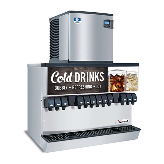
Servend MDH-402 Series Installation, Use & Care Manual
Ice & beverage dispensers icepic and selectable ice series
Hide thumbs
Also See for MDH-402 Series:
- Manual (2 pages) ,
- Technician's handbook (208 pages) ,
- Installation & service manual (64 pages)
Table of Contents
Advertisement
Advertisement
Table of Contents
Troubleshooting

Related Manuals for Servend MDH-402 Series


Summary of Contents for Servend MDH-402 Series
- Page 1 MDH-302/402 & icepic / Selectable Ice Series ™ Ice & Beverage Dispensers Installation, Use & Care Manual This manual is updated as new information and models are released. Visit our website for the latest manual. www.manitowocfsg.com Leader in Ice & Beverage Dispensers Part Number 020003999 6/14...
- Page 2 Safety Notices Read These Before Proceeding: As you work on Manitowoc equipment, be sure to pay close attention to the safety notices in this manual. ! Caution Disregarding the notices may lead to serious injury and/ Proper installation, care and maintenance are or damage to the equipment.
-
Page 3: Table Of Contents
Table of Contents Section 1 General Information Read This Manual ..........Unit Inspection . - Page 4 Table of Contents (continued) MDH-402 16 Valve Plumbing Diagrams ......2-11 MDH-402 16 Valve Flex Manifold (1 per side) ..... . . 2-11 MDH-402 20 Valve Plumbing Diagram .
- Page 5 Table of Contents (continued) Preventive Maintenance..........Disassembly .
- Page 6 Table of Contents (continued) Part Number 020003999 6/14...
-
Page 7: Read This Manual
Section 1 General Information Read This Manual Model Numbers Manitowoc Beverage Equipment (MBE) developed this This manual covers the following models: manual as a reference guide for the owner/operator and Beverage/Ice Dispensers installer of this equipment. Please read this manual before installation or operation of the machine. -
Page 8: Legs
General Information Section 1 LEGS Warranty Information Legs are optional equipment with most MBE dispensers. Consult your local MBS Distributor for terms and Standard legs are 4" (10.2 cm) tall stainless steel legs. If conditions of your warranty. Your warranty specifically an ice machine is installed on top of the dispenser, legs excludes all beverage valve brixing, general must not be installed. -
Page 9: General
Section 2 Installation Instructions General These instructions are provided to assist the qualified Important installer. Contact your Manitowoc Beverage Equipment Failure to follow these installation guidelines may Service Agent or call Manitowoc Beverage Equipment affect warranty coverage. for information regarding start-up services. Dimensions 3/4"... -
Page 10: Mdh-302 & 402 Footprint
Installation Instructions Section 2 MDH-302 & 402 Footprint Maximum Area for Cutout Minimum Area for Cutout Maximum Minimum Model MDH-302* 38.75" 20.50" 3.00" 32.00" (98.43 cm) (52.07 cm) (7.62 cm) (81.28 cm) MDH-402* 56.50" 21.40" 3.00" 48.00" (143.51 cm) (54.36 cm) (7.62 cm) (121.92 cm) ! Caution... -
Page 11: Location
Section 2 Installation Instructions Location The location selected for the beverage dispenser must LOCATION REQUIREMENTS FOR TOP MOUNTED ICE MACHINE INSTALLATIONS meet the following criteria. If any of these criteria are not met, select another location. Location — Avoid placing the dispenser and/or ice machine near heat sources such as radiators, ovens, •... -
Page 12: Pre-Installation Checklist
Installation Instructions Section 2 Pre-installation Checklist When installing any system, first make sure the major components are available. Generally the major components necessary for an installation are: Pre-mix System: Post Mix System: regulator set regulator set Product connectors for Figal tank Beverage dispenser Gas connectors for Figal tank Beverage tubing... -
Page 13: Double Check
Section 2 Installation Instructions DOUBLE CHECK ADDITIONAL CHECKS FOR TOP MOUNTED ICE MACHINE INSTALLATIONS Do you have enough space to install the Location — Avoid placing the dispenser and/or dispenser or a dispenser and top mounted ice ice machine near heat sources such as machine? radiators, ovens, refrigeration equipment and direct sunlight. -
Page 14: Assembly
Installation Instructions Section 2 Assembly INSTALLING BAFFLE FOR ICE MACHINE “Q” Series Baffle INSTALLATIONS 1. Position baffle on top of water well with tab on the front and the other tab inside the water well. “S” Series Baffle 2. Mount the baffle on the left side of the ice machine 1. -
Page 15: Electrical
Section 2 Installation Instructions Electrical GENERAL Grounding Instructions Warning Warning All wiring must conform to local, state and national Risk of electrical shock. Connect to a properly codes. grounded outlet only. MINIMUM CIRCUIT AMPACITY This appliance must be grounded. In the event of malfunction or breakdown, grounding provides a path of The minimum circuit ampacity is used to help select the least resistance for electric current to reduce the risk of... -
Page 16: Pump Deck Wiring
Installation Instructions Section 2 PUMP DECK WIRING Warning The supply cord is equipped with a three prong 5-15P. When using electric appliances, basic precautions When a Ground Fault Circuit Interrupter (GFCI) is should always be followed, including the following: required by code, a breaker type protector must be used. -
Page 17: Water Supply
Section 2 Installation Instructions Water Supply RECOMMENDED PLUMBING DIAGRAM LOCATION The plumbing diagram is printed on a white vinyl label, normally located above the inlet tubes for syrup and water. The plumbing diagram label can be accessed by removing the splash panel of the dispenser. The plumbing diagram label explains which inlet coldplate fittings supply which dispenser valves and water manifolds. -
Page 18: Mdh-302 12 Valve Plumbing Diagram
PART PART 2-1-1-2 FLEX 2-1-1-2 FLEX #5011803-1 #5011802-0 LEFT TO RIGHT LEFT TO RIGHT SERVEND RECOMMENDED PLUMBING SERVEND RECOMMENDED PLUMBING *OPTIONAL* VARIETY VALVE ON #3 1-WATER INTERNALLY CARBONATED UNITS: INTERNALLY CARBONATED UNITS: (THRU COLD PLATE) A. PLAIN WATER TO THE CARBONATOR A. -
Page 19: Mdh-402 16 Valve Plumbing Diagrams
Installation Instructions MDH-402 16 VALVE PLUMBING DIAGRAMS COLD CARB MDH-402 16 VALVE COLD CARB MDH-402 16 VALVE SERVEND RECOMMENDED PLUMBING SERVEND RECOMMENDED PLUMBING A. PLAIN WATER TO THE CARBONATOR A. PLAIN WATER TO THE CARBONATOR B. PLAIN WATER TO MANIFOLD B. -
Page 20: Mdh-402 20 Valve Plumbing Diagram
Section 2 MDH-402 20 VALVE PLUMBING DIAGRAM COLD CARB MDH-402 20 VALVE COLD CARB MDH-402 20 VALVE SERVEND RECOMMENDED PLUMBING SERVEND RECOMMENDED PLUMBING A. PLAIN WATER TO THE CARBONATOR A. PLAIN WATER TO THE CARBONATOR B. PLAIN WATER TO MANIFOLD B. -
Page 21: Co2 System
Section 2 Installation Instructions System ROUTING INTERNAL CARB TANK PURGE TUBE 3. Depending on drain location route the tubing through the tubing bundle cutout or out the back of Some models are equipped with an internal carbonation the dispenser. tank. These models require that the purge/pressure relief tubing be routed to a drain. -
Page 22: Step By Step Installation
Installation Instructions Section 2 Step by Step Installation GENERAL 2. Run the beverage lines and water lines; make sure to install the water connections to the proper inlets. MDH series dispensers have a stainless steel cabinet Connection “A” comes from the brass carbonator and lighted merchandiser standard. -
Page 23: Ada Key Pads
Section 2 Installation Instructions ADA KEY PADS These instructions are for installations with this option. 6. Connect the ADA ribbon cable to the ADA wire harness that is fastened to the foam front by a wire 1. Remove power from the unit. clip. -
Page 24: Starting Your Beverage System & Dispenser
Installation Instructions Section 2 ADA Key Pad Matrix 12 Valve Dispensers Cubed Crushed Cubed Crushed Cubed Crushed Cubed Crushed 16 Valve Dispensers Cubed Crushed Cubed Crushed Cubed Crushed Cubed Crushed 20 Valve Dispensers Cubed Crushed Cubed Crushed Cubed Crushed Cubed Crushed Finish Installation STARTING YOUR BEVERAGE SYSTEM &... -
Page 25: Operation
Section 3 Operation General System Overview NOTE: This is a simplified schematic to MDH Series show the basic operation of the beverage system. Internal Carbonation Beverage Dispensing System Dispenser Carbonated/Non-carbonated Beverage Manifolds Carbonator Tank Countertop SYRUP Tap Water Syrup Pump 1800 Tap Water SYRUP... -
Page 26: Mdh-302 Cold Carbonation System
Operation Section 3 MDH-302 Cold Carbonation System MDH-302 CUT-IN 70 PSI CUT-OUT 100 PSI MUNICIPAL WATER SUPPLY FILTRATION SYSTEM CARB TANK PLUMBING CHANGED TO A TEE FITTING ON UNITS WITH SERIAL NUMBER 610115880 AND UP FOR TANK PRESSURES REFER TO MANUAL FOR SPECIFICATIONS B.I.B. -
Page 27: Mdh-402 Cold Carbonation System
Section 3 Operation MDH-402 Cold Carbonation System MDH-402 CUT-IN 70 PSI BIB SET TO CUT-OUT 100 PSI 60 PSI MUNICIPAL WATER SUPPLY FILTRATION SYSTEM FOR TANK PRESSURES REFER TO MANUAL FOR SPECIFICATIONS REGULATOR 50-55 PSI PLAIN WATER PLAIN WATER TO MANIFOLD TO MANIFOLD (NON-INSULATED) (NON-INSULATED) -
Page 28: Component Identification
Operation Section 3 Component Identification Merchandiser Selectable Ice on Units with this Option Nozzles Nozzles Key Switch Ice Chute Nozzles Drain Pan Grid (Crushed Ice on icepic™) Splash Panel Drain Pan Sequence of Operation RECOMMENDED ICE OTHER ICE SIZES AND SHAPES 0.38"... -
Page 29: Ice Storage And Dispensing
Section 3 Operation ICE STORAGE AND DISPENSING merchandiser is removed, no power is available to the crusher or gear motor and no ice can be crushed and/or As the customer presses the rocking chute, the arm at dispensed. the top left rear of the chute pushes upward on the door lock. -
Page 30: Syrup Delivery System
Operation Section 3 Syrup Delivery System Your syrup location can vary depending on the volume the storage location. Adverse temperatures can affect of beverages served and ease of accessibility. Your the storage and quality of beverage products. It is beverage system may sit in a back storage room or recommended the temperature of storage location under the counter of the dispenser. -
Page 31: B-I-B
Section 3 Operation Racking FIGAL SYSTEM Regardless if you are working on a B-I-B or Figal Figal refers to the stainless steel tanks of pre-mix system, a place will be designated for placement of the beverage or post-mix syrup. A small CO tank pushes product. -
Page 32: Operation Checks & Adjustments
Operation Section 3 Operation Checks & Adjustments ICE DELIVERY SWITCH ADJUSTMENT CRUSHED OR CUBED DEFAULT To properly adjust the switch, first unplug the power cord For MDH Models equipped with Selectable Ice Modules, to the unit then remove the merchandiser. This will give this selectable ice option will allow the unit to always you access to the ice delivery switch located on the left default to either cube or crushed ice or remain at the last... -
Page 33: Maintenance
Section 4 Maintenance Cleaning Clean the dispensing valves: 6. Remove nozzles and diffusers from beverage DAILY CLEANING valves. All cleaning must meet your local health department regulations. The following cleaning instructions are provided as a guide. ! Caution Use only warm soapy water to clean the exterior of the tower. -
Page 34: Monthly Cleaning
Maintenance Section 4 MONTHLY CLEANING 6. Prepare 2 gallons of sanitizing solution by mixing 1/2 ounce of household bleach (that contains 5.25% sodium hypochlorite) with 2 gallons of 120°F (49°C) Warning water. The mixture must not exceed 100 PPM of Unplug unit before servicing or cleaning ice bin. -
Page 35: Preventive Maintenance
Section 4 Maintenance Preventive Maintenance Preventive maintenance is a vital part of keeping your dispenser in top condition. Following the guidelines below will assist you in continued trouble-free operation of your unit. 1. Conduct daily maintenance of the machine. 2. Perform monthly maintenance of the machine. 3. -
Page 36: Disassemble The Rocking Chute
Maintenance Section 4 7. On MDH models without a top mounted ice machine, remove the plastic lid from the top of the dispenser. 8. Remove all ice from the dispenser. 9. Disconnect electrical power to the dispenser. 10. Remove the strip lids off the top left and top right of the dispenser bin. - Page 37 Section 4 Maintenance 2. Remove the merchandiser. The merchandiser is 5. Remove the crusher drip pan by pulling up slightly removed by taking out the two (2) screws located at on the crusher assembly and pulling the drip pan the top of the merchandiser. Once the screws are away from the foam front.
-
Page 38: Monthly Ice Crusher Assembly Cleaning
Maintenance Section 4 MONTHLY ICE CRUSHER ASSEMBLY CLEANING Once the ice crusher hub assembly has been removed, HOUSING DOOR the crusher is ready to be cleaned and sanitized. Follow HOUSING the steps below for proper cleaning and sanitizing procedures. BLADE/HUB ASSEMBLY 1. -
Page 39: Reassemble The Ice Crusher Assembly
Section 4 Maintenance 4. Rinse all of the parts with clean water. REASSEMBLE THE ICE CRUSHER ASSEMBLY 5. Prepare 2 gallons of sanitizing solution by mixing a 1. Insert the blade assembly into the crusher housing. 1/2 ounce of household bleach (that contains 5.25% When inserting the blade assembly, align the sodium hypochlorite) with 2 gallons of 120°F (49°C) stationary blades with the locating slots in the... -
Page 40: Gear Motor Removal
Maintenance Section 4 6. Reattach the decorative ice chute by inserting the 8. Reinstall the merchandiser and secure with the two chute rod through the chute, housing mount and screws that were removed during disassembly. motor mount. Secure the chute rod by inserting 9. - Page 41 Section 4 Maintenance Front Serviceable These instructions are provided as a guide for the 6. Get correct alignment one of two ways: removal of the gear motor. Depending on the model a. Turn drive shaft with an adjustable wrench, number of your dispenser, these instructions may vary being careful not to damage the drive shaft.
-
Page 42: Sanitizing
Maintenance Section 4 Sanitizing BEVERAGE SYSTEM CLEANING 2. Disconnect the “syrup-line side” of the Bag-In-Box connector. Warning Flush sanitizing solution from syrup system. Residual sanitizing solution left in system could create a health hazard. Warning When using cleaning fluids or chemicals, rubber gloves and eye protection must be worn. -
Page 43: Figal Beverage System
Section 4 Maintenance 5. Draw rinse water through system until clean water is 2. Disconnect all product and water lines from product dispensed. Most beverage valves allow the syrup tanks and remove carbonator. side to be manually activated by depressing the 3. -
Page 44: Mdh Series Graphic Medallion Removal & Installation
Maintenance Section 4 MDH Series Graphic Medallion Removal & Installation The graphic medallions on the MDH Series Ice/Beverage Dispensers are made out of a flexible duratran that can be removed/replaced from the front of the unit without the use of tools (back-lit merchandiser light box does not need to be removed from the unit). -
Page 45: Checklist
Loaded ice not broken up (Caution: Break ice clusters before manually filling Super cooled ice is not covered by the the dispenser. (See ice Servend warranty.) recommendations.) Excessive water spilling from the ice Adjust ice machine to eliminate water machine spillage. -
Page 46: Icepic™ Troubleshooting
Before Calling for Service Section 5 icepic™ Troubleshooting Problem Possible Cause To Correct DISPENSER DOES NOT DISPENSE No power Check power source and power cord. CRUSHED ICE Loose wire in electrical system Check wiring. Dispense switch faulty Replace switch. Nothing is heard Crusher motor faulty Replace motor/gear box. -
Page 47: Pump Troubleshooting
Section 5 Before Calling for Service Pump Troubleshooting Problem Possible Cause Corrective Action Pump motor does not Problem with probe or probe harness 1. Remove probe electronics. shut off 2. Pass magnetic tip of screwdriver by lower end of tube extending from electronics package. -
Page 48: Drink Troubleshooting
Before Calling for Service Section 5 Drink Troubleshooting Condition Investigation Check Correction Water only dispensing No pressure Regulator(s) out of adjustment Check/adjust regulator(s). Out of CO Install fresh tank. Defective regulator(s) Check/repair/replace regulator(s). line pinched, kinked or Check/repair/replace CO line. obstructed Syrup and CO only... -
Page 49: Liquid Level Control Troubleshooting
Section 5 Before Calling for Service Liquid Level Control Troubleshooting START START Does Pump motor come on? Remove red Is pump Is pump Remove red and black motor motor operation and black wires from operation intermittent? wires from LLC. LLC. intermittent Does Does... - Page 50 Before Calling for Service Section 5 THIS PAGE INTENTIONALLY LEFT BLANK Part Number 020003999 6/14...
- Page 52 © 2014 Manitowoc Continuing product improvements may necessitate change of specifications without notice. Part Number 020003999 6/14 Manitowoc Beverage Systems 2100 Future Drive Sellersburg, IN 47172, USA Ph: 812-246-7000 Fax: 812-246-7024 Visit us online at: www.manitowocfsg.com...
Need help?
Do you have a question about the MDH-402 Series and is the answer not in the manual?
Questions and answers