Sign In
Upload
Download
Table of Contents
Contents
Add to my manuals
Delete from my manuals
Share
URL of this page:
HTML Link:
Bookmark this page
Add
Manual will be automatically added to "My Manuals"
Print this page
×
Bookmark added
×
Added to my manuals
Manuals
Brands
Servend Manuals
Beverage Dispenser
SV-200 SCI
Installation, use & care manual
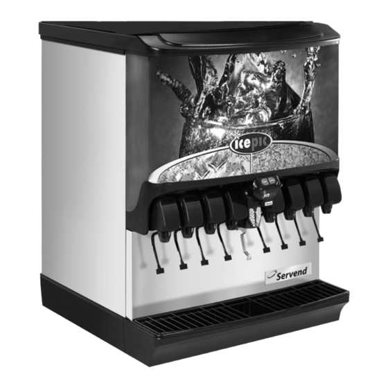
Servend SV-200 SCI Installation, Use & Care Manual
Selectable ice beverage/ice dispensers
Hide thumbs
1
2
Table Of Contents
3
4
5
6
7
8
9
10
11
12
13
14
15
16
17
18
19
20
21
22
23
24
25
26
27
28
29
30
31
32
33
34
35
36
37
38
39
40
41
42
43
44
45
46
47
48
49
50
51
52
page
of
52
Go
/
52
Contents
Table of Contents
Bookmarks
Table of Contents
Table of Contents
Read this Manual
Accessories
Manual Fill Lid for Dispensers with an Ice Machine
General
Dimensions
Footprint
Location
Location Requirements for Top Mounted Ice Machine Installations
Pre-Installation Checklist
Top Mounted Ice Machine Installations
Electrical
Pump Deck Wiring
Water Supply
Section 2
Installation Instructions
Capacities
CO 2 Supply
Routing Internal Carb Tank Purge Tube
Drains
Step by Step Installation
General
Specifications Chart
Unit Installation
Pre-MIX Pressures
Cold Carb and Ambient System Pressures
ADA Key Pads
Starting Your Beverage System & Dispenser
Section 3
Operation
General System Overview
Component Identification
Dispenser
Selectable Ice Module
Selectable Ice Module with Flavor Magic
Sequence of Operation
Ice Recommended for Dispensing
Ice Storage and Dispensing
Selectable Ice Sequence of Operation
Beverage Valves
Carbonation
Syrup Delivery System
Back Room Package
Racking
B-I-B
Pumps
Auto Bag Selectors
Figal System
Figal Tanks
Programming Modes
Flavor Magic Dispensing Modes
Control Logic Matrix - Flavor Magic
Section 4
Maintenance
Preventive Maintenance
Monthly Cleaning
Cleaning
Daily Cleaning
Disassembly
For Cleaning & Maintenance
Selectable Ice Crusher
Reassemble the Ice Crusher Assembly
Front Serviceable Gear Motor Removal
Sanitizing
Beverage System Cleaning
Bag-In-Box System Sanitation
Flavor Magic
Figal Beverage System
Shipping, Storage and Relocation
Checklist
Selectable Ice
Drinks
Flavor Shots
Advertisement
Quick Links
1
Manual Fill Lid for Dispensers with an Ice Machine
2
Electrical
3
Beverage Valves
Download this manual
Selectable Ice
Beverage/Ice Dispensers
Installation, Use & Care Manual
This manual is updated as new information and models are released.
Visit our website for the latest manual. www.manitowocfsg.com
Leader in Ice & Beverage Dispensers
Part Number 020003997
4/12
Table of
Contents
Previous
Page
Next
Page
1
2
3
4
5
Advertisement
Table of Contents
Need help?
Do you have a question about the SV-200 SCI and is the answer not in the manual?
Ask a question
Questions and answers
Related Manuals for Servend SV-200 SCI
Beverage Dispenser Servend Ice & Beverage Dispensing Units Technician's Handbook
Ice & beverage dispensing units (208 pages)
Beverage Dispenser Servend SV Series Installation, Use & Care Manual
Beverage/ice dispensers (52 pages)
Beverage Dispenser Servend S Series Installation, Use & Care Manual
Beverage/ice dispensers (52 pages)
Beverage Dispenser Servend STH14 Technician's Handbook
Servend ice & beverage dispensing units (204 pages)
Beverage Dispenser Servend SV-250 SCI Installation, Use & Care Manual
Selectable ice beverage/ice dispensers (52 pages)
Beverage Dispenser Servend SV-200 Manual
Selectable ice/beverage dispensers with ice crusher (2 pages)
Beverage Dispenser Servend SV-250 Manual
Selectable ice/beverage dispensers with ice crusher (2 pages)
Beverage Dispenser Servend MD 150 Installation & Service Manual
Md/mdh series beverage/ice dispensers (64 pages)
Beverage Dispenser Servend CEV SERIES Installation, Use & Care Manual
(40 pages)
Beverage Dispenser Servend MD-175 Quick Start Manual
Duratran/medallion replacement (2 pages)
Beverage Dispenser Servend MDH-402 Series Installation, Use & Care Manual
Ice & beverage dispensers icepic and selectable ice series (52 pages)
Beverage Dispenser Servend CF-1522 Installation, Use & Care Manual
(34 pages)
Beverage Dispenser Servend MDH-402 Manual
Dual selectable ice/beverage dispenser with icepic integrated ice crusher (2 pages)
Beverage Dispenser Servend 2P FS Installation, Use & Care Manual
Beverage & flavor shot towers (25 pages)
Beverage Dispenser Servend FlexTower 8 Installation & Service Manual
Flextower series 8, 12 and 16 flavor beverage dispensers (40 pages)
Beverage Dispenser Servend 5030763 Installation & Service Manual
Beverage & flavor shot towers (20 pages)
This manual is also suitable for:
Sv-200i sci
Sv-250i sci
Sv-250 sci
Table of Contents
Print
Rename the bookmark
Delete bookmark?
Delete from my manuals?
Login
Sign In
OR
Sign in with Facebook
Sign in with Google
Upload manual
Upload from disk
Upload from URL


Need help?
Do you have a question about the SV-200 SCI and is the answer not in the manual?
Questions and answers