
Related Manuals for Black Horse Model CHIPMUNK


Summary of Contents for Black Horse Model CHIPMUNK
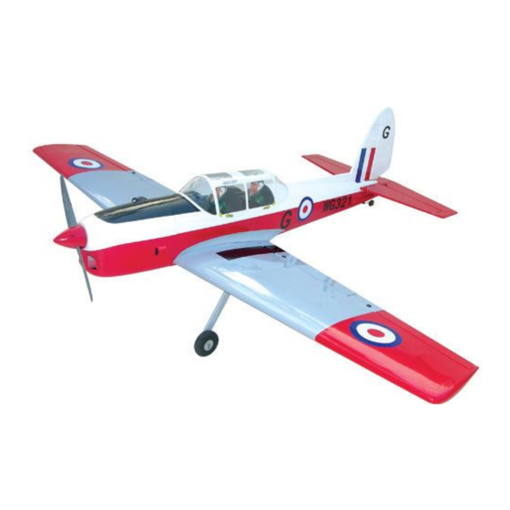
- Page 1 INSTRUCTION MANUAL BOOK. SPECIFICATION Wingspan 164 cm 64.57in. Length 135 cm 53.15 in. Weight 3.3kg 7.26 lbs. Servo 7 servos. Radio 4 channels. Engine 61 cu.in-2 stroke. 91 cu.in-4 stroke. Made in Vietnam.
- Page 2 CHIPMUNK. INSTRUCTION MANUAL. This instruction manual is designed to help you build a great flying aeroplane. Please read this manual thoroughly before starting assembly of your CHIPMUNK. Use the parts listing below to identify all parts. WARNING. Please be aware that this aeroplane is not a toy and if assembled or used incorrectly it is capable of causing injury to people or property.
-
Page 3: Safety Precaution
CHIPMUNK. INSTRUCTION MANUAL. INSTALLING THE AILERON- FLAP SERVOS. SAFETY PRECAUTION. 1. Install the rubber grommets and brass + This is not a toy eyelets onto the aileron and flap servo. + Be sure that no other flyers are using your radio frequency. - Page 4 CHIPMUNK. INSTRUCTION MANUAL. Aileron servo tray Flap servo tray. C/A glue C/A glue Servo tray. Flap. Aileron. Bottom side. 2. Using a modeling knife, remove the cov- ering servo tray.
- Page 5 CHIPMUNK. INSTRUCTION MANUAL. 3. Drill 1,5mm pilot holes through the block of wood for each of the four mounting screws provided with the servo. Install servo into aileron servo tray as same as picture below. 2 x 10 mm. Secure 4.
- Page 6 CHIPMUNK. INSTRUCTION MANUAL. Flap. Aileron. 3. Install control horn as same as picture Repeat the procedure for the other wing below. half. INSTALLING THE AILERON - FLAP SERVO CONTROL HORN. 1. Using a ruler & pen to draw a straight line as below picture.
- Page 7 CHIPMUNK. INSTRUCTION MANUAL. aileron control horn Control horn. Flap 5. Install control horn as same as picture below as same as the way of aileron. Nilon control clasp. M3 lock nut. 3mm x 50mm. C/A glue. Flap. C/A glue.
-
Page 8: Installing The Aileron Linkages
CHIPMUNK. INSTRUCTION MANUAL. 4. Locate one nylon servo arm, and using wire cutters,remove all but one of the arms. Using a 2mm drill bit, enlarge the third hole out from the center of the arm to accommodate the aileron pushrod wire. -
Page 9: Joining The Wing Halves
CHIPMUNK. INSTRUCTION MANUAL. Repeat the procedure for the other wing Bottom side half. Flap Aileron finishing Flap. Top side JOINING THE WING HALVES. 1. Location the aluminium wing dihedral brace. Flap. 2. Using a modeling knife, remove the cov- ering wing. - Page 10 CHIPMUNK. INSTRUCTION MANUAL. Remove covering. Masking tape. Apply masking tape. Epoxy glue. Aluminium brace. Dowel brace.
-
Page 11: Installing Landing Gear
CHIPMUNK. INSTRUCTION MANUAL. Bottom side. INSTALLING LANDING GEAR. Mark point. 3x12mm Wing bolt plate. Insert the wing bolt plate. - Page 12 CHIPMUNK. INSTRUCTION MANUAL. Mark point Remove covering. 1mm drill bit.
- Page 13 CHIPMUNK. INSTRUCTION MANUAL. C/A glue. Apply masking tape...
-
Page 14: Engine Mount
CHIPMUNK. INSTRUCTION MANUAL. ENGINE MOUNT. See pictures below: 3.5x25mm. 4x25mm. - Page 15 CHIPMUNK. INSTRUCTION MANUAL. FUEL TANK. INSTALLING THE STOPPER ASSEMBLY 1. The stopper has been pre-assembled at the factory. 2. Using a modeling knife, cut one length of silicon fuel line (the length of silicon fuel line is calculated by how the weighted clunk should rest about 8mm away from the rear of the tank and move freely inside the tank).
- Page 16 CHIPMUNK. INSTRUCTION MANUAL. 5. Test fit the stopper assembly into the Do not secure the tank into place tank. It may be necessary to remove some of permanently until after balancing the airplane. the flashing around the tank opening using You may need to remove the tank to mount a modeling knife.
-
Page 17: Installing The Engine
CHIPMUNK. INSTRUCTION MANUAL. INSTALLING THE ENGINE. Locate the long piece of wire used for the throttle pushrod. One end of the wire has been Fuel tank tray. pre-bend in to a “Z” bend at the factory. This “Z” bend should be inserted into the throttle arm of the engine when the engine is fitted onto the engine mount. - Page 18 CHIPMUNK. INSTRUCTION MANUAL. COWLING. 1. Slide the fiberglass cowl over the en- gine and line up the back edge of the cowl with the marks you made on the fuselage. Trim and cut.
- Page 19 CHIPMUNK. INSTRUCTION MANUAL. 3 x 10 mm. 2. While keeping the back edge of the cowl flush with the marks, align the front of the cowl with the crankshaft of the engine. The front of the cowl should be positioned so the crankshaft is in nearly the middle of the cowl opening.
-
Page 20: Installing The Spinner
CHIPMUNK. INSTRUCTION MANUAL. INSTALLING THE SPINNER. ELEVATOR INSTALLATION. 1. Install the rubber grommets and brass 3 x 12mm. collets into the elevator servo. Test fit the servo into the servo tray. 2. Mount the servo to the tray using the mounting screws provided with your radio system. - Page 21 CHIPMUNK. INSTRUCTION MANUAL. C/A glue C/A glue Elevator servo. HORIZONTAL STABILIZER INSTALLATION. C/A glue Horizontal stabilize installation . See picture below. 1. Using a modeling knife, cut away the covering from the fuselage for the stabilizer and remove it. Remove covering.
- Page 22 CHIPMUNK. INSTRUCTION MANUAL. 2. Draw a center line onto the horizontal 4. Remove the stabilizer. Using the lines stabilizer. Then slide the horizontal into the you just drew as a guide, carefully remove the fuselage. covering from between them using a modeling knife.
- Page 23 CHIPMUNK. INSTRUCTION MANUAL. M3 lock nut. 3mm x 30mm. Nilon control clasp. Control horn of elevator. 5. When you are sure that everything is aligned correctly, mix up a generous amount of 30 minute epoxy. Apply a thin layer to the...
-
Page 24: Elevator Pushrod Installa- Tion
CHIPMUNK. INSTRUCTION MANUAL. Top side C/A glue. ELEVATOR PUSHROD INSTALLA- TION. C/A glue. Elevator Elevator pushrod. pushrod. Elevator control horn. -
Page 25: Vertical Stabilizer
CHIPMUNK. INSTRUCTION MANUAL. Cut. Elevator servo. Bend and cut. VERTICAL STABILIZER. - Page 26 CHIPMUNK. INSTRUCTION MANUAL. Pen. Hinge. 4. Now, remove the rudder and using a 1. Using a modeling knife cut away the modeling knife, carefully cut just inside the covering from the top of the fuselage and re- marked lines and remove the film of the rudder.
-
Page 27: Mounting The Tail Wheel Bracket
CHIPMUNK. INSTRUCTION MANUAL. 6. When you are sure that everything is a 1. Set the tail wheel assembly in place aligned correctly, mix up a generous amount on the plywood plate. The pivot point of the of 30 minute epoxy. Apply a thin layer to the... - Page 28 CHIPMUNK. INSTRUCTION MANUAL. RUDDER CONTROL HORN THE INSTALLATION. Rudder Rudder control horn pushrod C/A glue. Top of elevator. Mark made. 18mm. Remove covering. Carefully make a 90 degree bend down at the mark made. Cut off the excess wire, leaving about 20mm beyond the bend.
- Page 29 CHIPMUNK. INSTRUCTION MANUAL. Epoxy glue. Push C/A glue Control horn rudder Rudder pushrod...
-
Page 30: Rudder Pushrod Installa- Tion
CHIPMUNK. INSTRUCTION MANUAL. RUDDER PUSHROD INSTALLA- Rudder pushdrod TION. Bend and cut. Elevator pushdrod Elevator pushdrod Cut. Cut. Rudder servo. - Page 31 CHIPMUNK. INSTRUCTION MANUAL. Remove covering. C/A glue Bottom side Top side Epoxy glue. Covered wood filler piece Bottom side Push C/A glue Insert covered wood filler piece as picture...
-
Page 32: Installing The Throttle Pushrod
CHIPMUNK. INSTRUCTION MANUAL. C/A glue Epoxy glue. Remove covering. C/A glue C/A glue Remove covering. INSTALLING THE THROTTLE PUSHROD. 1. Install one adjustable metal connector through the third hole out from the center of one servo arm, enlarge the hole in the servo arm using a 2mm drill bit to accommodate the servo connector. -
Page 33: Installing The Switch
CHIPMUNK. INSTRUCTION MANUAL. C o n n e c - tor. Servo arm. After installing the adjustable metal connector apply a small drop of thin C/A to the bottom nut. This will prevent the connector from loosening during flight. Rudder servo. -
Page 34: Installing The Receiver And Battery
CHIPMUNK. INSTRUCTION MANUAL. Tie wrap. Tie wrap. Battery. Switch. INSTALLING THE RECEIVER AND BATTERY. 1. Plug the servo leads and the switch lead into the receiver. You may want to plug an aileron extension into the receiver to make plugging in the aileron servo lead easier when you are installing the wing . -
Page 35: Wing Attachment
CHIPMUNK. INSTRUCTION MANUAL. Receiver. Wing bolt. WING ATTACHMENT. See picture wing attach to fuselage. - Page 36 CHIPMUNK. INSTRUCTION MANUAL. Epoxy glue. Cut. C/A glue...
-
Page 37: Control Throws
CHIPMUNK. INSTRUCTION MANUAL. CONTROL THROWS. BALANCING. 1. It is critical that your airplane be balanced 1. We highly recommend setting up a plane correctly. Improper balance will cause your using the control throws listed. plane to lose control and crash. - Page 38 CHIPMUNK. INSTRUCTION MANUAL.
Need help?
Do you have a question about the CHIPMUNK and is the answer not in the manual?
Questions and answers