Sign In
Upload
Manuals
Brands
Kramer Manuals
Matrix Switcher
VS-3232A
Kramer VS-3232A Audio Matrix Switcher Manuals
Manuals and User Guides for Kramer VS-3232A Audio Matrix Switcher. We have
2
Kramer VS-3232A Audio Matrix Switcher manuals available for free PDF download: User Manual
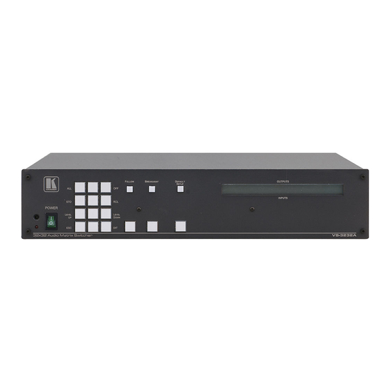
Kramer VS-3232A User Manual (70 pages)
32x32 Audio Matrix Switcher
Brand:
Kramer
| Category:
Matrix Switcher
| Size: 3 MB
Table of Contents
Table of Contents
2
1 Introduction
6
2 Getting Started
6
Quick Start
6
3 Overview
8
4 Your Balanced Stereo Audio Matrix Switcher
8
Figure 1: Front Panel VS-3232A 32X32 Audio Matrix Switcher
9
Table 1: Front Panel VS-3232A 32X32 Audio Matrix Switcher Features
10
Figure 2: VS-3232A Keypad Selector Buttons
11
Table 2: VS-3232A Keypad Selector Buttons Functions
11
Figure 3: Rear Panel VS-3232A 32X32 Audio Matrix Switcher
12
Using the IR Transmitter
13
Table 3: Rear Panel VS-3232A 32X32 Audio Matrix Switcher Features
13
5 Installing the VS-3232A in a Rack
14
6 Connecting a Single VS-3232A 32X32 Audio Matrix Switcher
15
Figure 4: Connecting the VS-3232A Audio Matrix Switcher
15
Connecting the Balanced/Unbalanced Stereo Audio Input/Output
16
Figure 5: Connecting a Balanced VS-3232A Stereo Audio Input and Output
16
Figure 6: Connecting an Unbalanced VS-3232A Stereo Audio Input
16
Figure 7: Connecting an Unbalanced VS-3232A Stereo Audio Output
16
7 VS-3232A 32X32 Audio Matrix Switcher Configurations
17
The VS-3232A Configuration Setups
17
The Follow-System Configuration Setup
17
Figure 8: Connecting in the Follow-System Configuration Setup
18
The Master/Slave Configuration Setup
19
Figure 9: Connecting in the Master/Slave Configuration Setup
20
The Follow-System Versus the Master/Slave Configuration Setups
21
Figure 10: the Follow-System Combined with the Master/Slave Configuration Setup
21
Table 4: Follow-System Versus the Master/Slave Configuration Setup
21
Assembling a Multi-Channel Audio Switcher
22
Figure 11: Configuring a 4-Channel 32X32 Switcher with Two VS-3232A Switchers
22
Connecting the VS-3232A as a Companion to the VS-3232V(Xl)
23
Figure 12: Connecting the VS-3232A as a Companion to the VS-3232Vxl
23
Connecting the VS-3232A as a Companion to a Multi-Channel Video Switcher
24
Figure 13: Connecting the VS-3232A as a Companion to a Multi-Channel Switcher
24
DIP-Switch Settings
25
Figure 14: DIP-Switches
25
Table 5: DIP-Switch Settings for VS-3232A and VS-3232V(Xl) Switchers
25
Table 6: DIP-Switch Definitions
25
Setting the Machine
26
Connecting a Control Interface
26
Connecting the RS-232 Control Interface
26
Table 7: Machine # DIP-Switch Settings
26
Figure 15: Connecting a PC to Two VS-3232A Units
27
Connecting the RS-485 Control Interface
28
Figure 16: RS-485 Connector PINOUT
28
Figure 17: Connecting the RS-485 Connectors between VS-3232A/VS-3232V(Xl) Units
29
Setting the Sync
30
Figure 18: RS-485 Control Interface and SYNC Connections
30
Controlling Via the ETHERNET
31
Connecting the ETHERNET Port Directly to a PC (Crossover Cable)
31
Connecting the ETHERNET Port Via a Network Hub (Straight-Through Cable)
32
Control Configuration Via the Ethernet Port
32
Figure 19: Local Area Connection Properties Window
32
Figure 20: Internet Protocol (TCP/IP) Properties Window
32
8 Operating Your Video Matrix Switcher
33
Startup Display
33
Figure 21: Default Startup Status Display Sequence
33
Viewing the Display
34
Using the Keypad Buttons
34
Confirming Actions
34
Toggling between the at Once and Confirm Modes
35
Confirming a Switching Action
35
Switching Options
35
Switching One Input to One Output
36
Switching Several Inputs to Several Outputs
36
Switching One Input to All Outputs
37
Clearing an Output
37
Clearing Several Outputs
37
Clearing All Outputs
37
Storing and Recalling Setups
38
Storing Setups
38
Recalling Setups
39
Using the DEFAULT SETUP Button (Unity Setting)
39
Choosing the FOLLOW or the BREAKAWAY Modes
40
Using the LOCK Button
42
Setting the Input/Output Volume
42
Table 8: Audio Output Attenuation Steps
42
9 The MENU Commands
44
Figure 22: Setting the SYNC Configuration (an Example)
45
Selecting the Audio Switching Method
46
Selecting the SYNC Configuration
46
Selecting the INTERFACE Configuration
46
Table 9: Audio Switching Method Configuration Menu
46
Table 10: SYNC Configuration Menu
46
Table 11: INTERFACE Configuration Menu
46
Selecting the Interface REPLY Configuration
47
Selecting the PROTOCOL Configuration
47
Selecting the Store DEFAULT Setup Configuration
47
Table 12: Interface REPLY Configuration Menu
47
Table 13: PROTOCOL Configuration Menu
47
Selecting the Initialization Sequence Delay Time for a Slave Unit
48
The Main Firmware Version
48
Table 14: Initialization Sequence Delay Time
48
Selecting the TOTAL RESET Option
49
Table 15: Total Reset Menu
49
10 Flash Memory Upgrade
50
Switcher Flash Memory Upgrade
50
Downloading from the Internet
50
Connecting the PC to the RS-232 Port
50
Upgrading Firmware
51
Figure 23: Splash Screen
51
Figure 24: Atmel – Flip Window
51
Figure 25: Device Selection Window
52
Figure 26: Device Selection Window
52
Figure 27: Loading the Hex
53
Figure 28: RS-232 Window
53
Figure 29: Atmel – Flip Window (Connected)
54
Figure 30: Atmel – Flip Window (Operation Completed)
54
Ethernet Flash Memory Upgrade
55
Downloading from the Internet
55
Connecting the PC to the RS-232 Port
55
Upgrading Firmware
56
Figure 31: the KFR-Programmer Window
56
11 Technical Specifications
57
Table 16: Technical Specifications of the VS-3232A Video Matrix Switcher
57
Audio Performance Graphs
58
Figure 32: Frequency Response (Bandwidth) of the VS-3232A
58
Figure 33: THD+N of the VS-3232A
58
Figure 34: Maximum Input/Output Level at 1Khz
58
12 Communication Protocols
59
The Kramer 2000 Communication Protocol
59
Figure 35: Linearity of the VS-3232A
59
Figure 36: Spectrum Plot of the Output Signal for a 1Khz, 4Dbu Input
59
Table 17: Hex Table (in 1-32 to out 1-16)
60
Table 18: Hex Table (in 1-32 to out 17-32)
62
Audio Gain/Attenuation Commands
64
ASCII (Sierra) Protocol for 3232A Series Switcher
65
ASCII Protocol Available Commands
65
Kramer: Simple Creative Technology
65
Advertisement
Kramer VS-3232A User Manual (65 pages)
32x32 Audio Matrix Switcher
Brand:
Kramer
| Category:
Matrix Switcher
| Size: 6 MB
Table of Contents
Table of Contents
2
1 Introduction
5
2 Getting Started
5
Quick Start
5
Now Appear in 11 Groups
5
3 Overview
7
4 Your Balanced Stereo Audio Matrix Switcher
7
Figure 1: Front Panel VS-3232A 32X32 Audio Matrix Switcher
8
Table 1: Front Panel VS-3232A 32X32 Audio Matrix Switcher Features
9
Figure 2: VS-3232A Keypad Selector Buttons
10
Table 2: VS-3232A Keypad Selector Buttons Functions
10
Figure 3: Rear Panel VS-3232A 32X32 Audio Matrix Switcher
11
Using the IR Transmitter
12
Table 3: Rear Panel VS-3232A 32X32 Audio Matrix Switcher Features
12
5 Installing the VS-3232A in a Rack
13
6 Connecting a Single VS-3232A 32X32 Audio Matrix Switcher
14
Figure 4: Connecting the VS-3232A Audio Matrix Switcher
14
Connecting the Balanced/Unbalanced Stereo Audio Input/Output
15
Figure 5: Connecting a Balanced VS-3232A Stereo Audio Input and Output
15
Figure 6: Connecting an Unbalanced VS-3232A Stereo Audio Input
15
Figure 7: Connecting an Unbalanced VS-3232A Stereo Audio Output
15
7 VS-3232A 32X32 Audio Matrix Switcher Configurations
16
The VS-3232A Configuration Setups
16
The Follow-System Configuration Setup
16
Figure 8: Connecting in the Follow-System Configuration Setup
17
The Master/Slave Configuration Setup
18
Figure 9: Connecting in the Master/Slave Configuration Setup
19
The Follow-System Versus the Master/Slave Configuration Setups
20
Figure 10: the Follow-System Combined with the Master/Slave Configuration Setup
20
Table 4: Follow-System Versus the Master/Slave Configuration Setup
20
Assembling a Multi-Channel Audio Switcher
21
Figure 11: Configuring a 4-Channel 32X32 Switcher with Two VS-3232A Switchers
21
Figure 12: Connecting the VS-3232A as a Companion to the VS-3232Vxl
22
Connecting the VS-3232A as a Companion to the VS-3232V(Xl)
22
Connecting the VS-3232A as a Companion to a Multi-Channel Video Switcher
23
DIP-Switch Settings
24
Figure 14: DIP-Switches
24
Table 5: DIP-Switch Settings for VS-3232A and VS-3232V(Xl) Switchers
24
Table 6: DIP-Switch Definitions
24
Setting the Machine
25
Connecting a Control Interface
25
Connecting the RS-232 Control Interface
25
Table 7: Machine # DIP-Switch Settings
25
Figure 15: Connecting a PC to Two VS-3232A Units
26
Connecting the RS-485 Control Interface
27
Figure 16: RS-485 Connector PINOUT
27
Figure 17: Connecting the RS-485 Connectors between VS-3232A/VS-3232V(Xl) Units
28
Setting the Sync
29
Figure 18: RS-485 Control Interface and SYNC Connections
29
Controlling Via the ETHERNET
30
Connecting the ETHERNET Port Directly to a PC (Crossover Cable)
30
Connecting the ETHERNET Port Via a Network Hub (Straight-Through Cable)
31
Control Configuration Via the Ethernet Port
31
Figure 19: Local Area Connection Properties Window
31
Figure 20: Internet Protocol (TCP/IP) Properties Window
31
8 Operating Your Video Matrix Switcher
32
Startup Display
32
Figure 21: Default Startup Status Display Sequence
32
Viewing the Display
33
Using the Keypad Buttons
33
Confirming Actions
33
Toggling between the at Once and Confirm Modes
34
Confirming a Switching Action
34
Switching Options
34
Switching One Input to One Output
35
Switching Several Inputs to Several Outputs
35
Switching One Input to All Outputs
36
Clearing an Output
36
Clearing Several Outputs
36
Clearing All Outputs
36
Storing and Recalling Setups
37
Storing Setups
37
Recalling Setups
38
Using the DEFAULT SETUP Button (Unity Setting)
38
Choosing the FOLLOW or the BREAKAWAY Modes
39
Using the LOCK Button
41
Setting the Input/Output Volume
41
9 The MENU Commands
43
Figure 22: Setting the SYNC Configuration (an Example)
44
Selecting the Audio Switching Method
45
Selecting the SYNC Configuration
45
Selecting the INTERFACE Configuration
45
Table 8: Audio Switching Method Configuration Menu
45
Table 9: SYNC Configuration Menu
45
Table 10: INTERFACE Configuration Menu
45
Selecting the Interface REPLY Configuration
46
Selecting the PROTOCOL Configuration
46
Selecting the Store DEFAULT Setup Configuration
46
Table 11: Interface REPLY Configuration Menu
46
Table 12: PROTOCOL Configuration Menu
46
Selecting the Initialization Sequence Delay Time for a Slave Unit
47
The Main Firmware Version
47
Table 13: Initialization Sequence Delay Time
47
Selecting the TOTAL RESET Option
48
Table 14: Total Reset Menu
48
10 Flash Memory Upgrade
49
Switcher Flash Memory Upgrade
49
Downloading from the Internet
49
Connecting the PC to the RS-232 Port
49
Upgrading Firmware
50
Figure 23: Splash Screen
50
Figure 25: Device Selection Window
51
Figure 26: Device Selection Window
51
Figure 27: Loading the Hex
52
Figure 28: RS-232 Window
52
Ethernet Flash Memory Upgrade
54
Downloading from the Internet
54
Connecting the PC to the RS-232 Port
54
Upgrading Firmware
55
Figure 31: the KFR-Programmer Window
55
11 Technical Specifications
56
Table 15: Technical Specifications of the VS-3232A Video Matrix Switcher
56
Audio Performance Graphs
57
Figure 32: Frequency Response (Bandwidth) of the VS-3232A
57
Figure 33: THD+N of the VS-3232A
57
Figure 34: Maximum Input/Output Level at 1Khz
57
12 Communication Protocols
58
The Kramer 2000 Communication Protocol
58
Figure 35: Linearity of the VS-3232A
58
Figure 36: Spectrum Plot of the Output Signal for a 1Khz, 4Dbu Input
58
Table 16: Hex Table (in 1-32 to out 1-16)
59
Table 17: Hex Table (in 1-32 to out 17-32)
61
ASCII Protocol: General
63
ASCII Protocol: Description
63
Advertisement
Related Products
Kramer VS-3232DN
Kramer VS-3232D
Kramer VS-3232Vxl
Kramer VS-3232V
Kramer VS-3232DVI
Kramer VS-3232DN-EM
Kramer VS-34FD
Kramer VS-44HC
Kramer VS-44HN
Kramer VS-44FO
Kramer Categories
Matrix Switcher
Switch
Media Converter
Amplifier
Receiver
More Kramer Manuals
Login
Sign In
OR
Sign in with Facebook
Sign in with Google
Upload manual
Upload from disk
Upload from URL