Stanley DL07 Operation And Service Manual
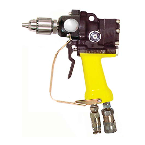
Hydraulic drill
Hide thumbs
Also See for DL07:
- User manual (18 pages) ,
- Service manual (22 pages) ,
- User manual (16 pages)
Table of Contents
Advertisement
Quick Links
DL07
HYDRAULIC
DRILL
WARNING
WARNING
To avoid serious injury or death
Wear Eye
Read the Manual
Protection
S
, O
M
AFETY
PERATION AND
AINTENANCE
Wear Ear
Wear Dust Mask
Protection
SERVICE MANUAL
Stanley Hydraulic Tools
3810 SE Naef Road
Milwaukie OR 97267-5698
Copyright
©
The Stanley Works 2006
503-659-5660
Printed in U.S.A.
FAX 503-652-1780
60789 12/2006 ver 4D
www.stanley-hydraulic-tools.com
Advertisement
Table of Contents

Related Manuals for Stanley DL07


Summary of Contents for Stanley DL07
- Page 1 Protection AFETY PERATION AND AINTENANCE Wear Ear Wear Dust Mask Protection SERVICE MANUAL Stanley Hydraulic Tools 3810 SE Naef Road Milwaukie OR 97267-5698 Copyright © The Stanley Works 2006 503-659-5660 Printed in U.S.A. FAX 503-652-1780 60789 12/2006 ver 4D www.stanley-hydraulic-tools.com...
-
Page 3: Table Of Contents
DL07 PARTS LIST........................21 WARRANTY ..........................22 SERVICING THE STANLEY HYDRAULIC IMPACT WRENCH: This manual contains safety, operation, and routine maintenance instructions. Servicing of hydraulic tools, other than routine maintenance, must be performed by an authorized and certifi ed dealer. Please read the following warning. - Page 4 1994 Self EN ISO 3744 1995 Self 28662-1 1988 Self Special Provisions: None Spezielle Bestimmungen: Dispositions particulières: Provisiones especiales: Disposizioni speciali: Done at/Ort/Fait à/Dado en/Fatto a Stanley Hydraulic Tools, Milwaukie, Oregon USA Date/Datum/le/Fecha/Data Signature/Unterschrift/Signature/Firma/Firma Position/Position/Fonction/Puesto/Posizione Engineering Manager Rev 1 3/05...
-
Page 5: Safety Symbols
SAFETY SYMBOLS Safety symbols and signal words, as shown below, are used to emphasize all operator, maintenance and repair actions which, if not strictly followed, could result in a life-threatening situation, bodily injury or damage to equip- ment. This is the safety alert symbol. It is used to alert you to potential personal injury hazards. -
Page 6: Safety Precautions
If so, place the added precautions in the space provided on page 5. The model DL07 Hydraulic Impact Wrench will provide safe and dependable service if operated in accordance with the instructions given in this manual. Read and un- derstand this manual and any stickers and tags attached to the tool and hose before operation. -
Page 7: Tool Stickers & Tags
USE ONLY PARTS AND REPAIR USE ONLY PARTS AND REPAIR PROCEDURES APPROVED BY PROCEDURES APPROVED BY and understand the safety STANLEY AND DESCRIBED IN THE OPERA- STANLEY AND DESCRIBED IN THE OPERA- TION MANUAL. TION MANUAL. instructions listed on this... -
Page 8: Tool Hose Information
The rated working pressure of the hydraulic hose must be equal to or higher than the relief valve setting on the hydraulic system.There are three types of hydraulic hose that meet this requirement and are authorized for use with Stanley Hydraulic Tools. -
Page 10: Htma Requirements
HTMA REQUIREMENTS TOOL CATEGORY HYDRAULIC SYSTEM REQUIREMENTS TYPE 1 TYPEII TYPEIII TYPE RR FLOW RATE 4-6 gpm 7-9 gpm 11-13 gpm 9-10.5 gpm (15-23 lpm) (26-34 lpm) (42-49 lpm) (34-40 lpm) TOOL OPERATING PRESSURE 2000 psi 2000 psi 2000 psi 2000 psi (at the power supply outlet) (138 bar) -
Page 11: Operation
Brittle material such as rock, brick or concrete can be drilled effi ciently when the bit is caused to strike (hammer) The DL07 can be confi gured to run on OC or CC circuits. the hole bottom to break up the material. Without hammer- ing, the rotating bit will only grind down and become dull. -
Page 12: Cold Weather Operation
OPERATION Ductile material such as metal or wood is drilled effi ciently when a steady down force is applied to the drill center to cause the bit to slice chips of material from the hole bottom. When drilling in metal, use a cutting lubricant to prolong bit life and reduce the amount of force required to drill effec- tively. -
Page 13: Equipment Protection & Care
fl ow. This can cause damage to internal seals. • Always replace hoses, couplings and other parts with replacement parts recommended by Stanley Hydraulic Tools. Supply hoses must have a minimum working pressure rating of 2500 psi/172 bar. -
Page 14: Troubleshooting
TROUBLESHOOTING If symptoms of poor performance develop, the following chart can be used as a guide to correct the problem. When diag- nosing faults in operation of the wrench, always check that the hydraulic power source is supplying the correct hydraulic fl... -
Page 15: Specifications
SPECIFICATIONS Drive Size .......................... 1/2 inch / 1.3 cm 3-Jaw Adjustable 5/8 -16 THD Chuck Drill Torque ........................20 ft lbs / 27 Nm at 2000 psi / 140 bar Drill Speed ............................1000 rpm at 8 gpm / 30 lpm RPM Range ................................350-1500 Weight ................................. -
Page 16: Accessories
ACCESSORIES DESCRIPTION PART NUMBER WOOD AUGER BITS, 5/8 INCH HEX 9/16 inch dia x 18 inch Carbide Tipped Auger Bit (22 inch OAL) ................. 27845 13/16 inch dia x 18 inch Carbide Tipped Auger Bit (22 inch OAL) ................27847 WOOD AUGER BITS, 7/16 INCH HEX 9/16 inch dia x 8 inch Carbide Tipped Auger Bit (12 inch OAL) ................... -
Page 17: Service
SERVICE chuck end. Do not reuse the ball bearing once it has been PRIOR TO DISASSEMBLY removed from the output shaft. 7. Remove the output shaft seal (30) by pressing it from Note: the gear housing bore. For orientation of parts in the following procedures, refer to the parts drawing later in this manual 8. - Page 18 SERVICE CLEANING AND INSPECTION TOOL REASSEMBLY CLEANING 1. Lubricate and install a new o-ring (4) and back-up ring (39) into the main housing. Install the seal back-up washer (44) and retaining ring (16). Clean all parts with a de-greasing solution. Blow dry with compressed air or use lint-free cloths.
- Page 19 SERVICE 10. Lubricate and install the shaft seal (30) into the gear housing. Install shaft keeper (24) and bearing keeper (25) beofre installing bearing (28) on output shaft (36). Install planet gears (26) into output shaft and install the output shaft with aqttached parts into the gear housing (69).
-
Page 20: Dl07 Parts Illustration
DL07 PARTS ILLUSTRATION... -
Page 21: Dl07 Parts List
RAILROAD HELP DESK STICKER 25610 (DL07552S, 552SUP, 572S ONLY) 01262 O-RING 28323 CE STICKER (DL0755001 ONLY) 01604 O-RING 60807 DL07 MODEL NUMBER STICKER 02324 CAP AND PLUG, 1/2 INCH 28788 MANUAL STICKER 03288 CAP AND PLUG, 3/8 INCH 03364 O-RING 29148... -
Page 22: Warranty
fi rst retail purchaser, or for a period of 2 years from the shipping date from Stanley, whichever period expires fi rst, to be free of defects in material and/or workmanship at the time of delivery, and will, at its option, repair or replace any tool or part of a tool, or new part, which is found upon examination by a Stanley authorized service outlet or by Stanley’s factory in Milwaukie, Oregon to be DEFECTIVE IN MATERIAL AND/OR WORKMANSHIP. - Page 23 Stanley Hydraulic Tools 3810 SE Naef Road Milwaukie, Oregon 503-659-5660 / Fax 503-652-1780 www.stanley-hydraulic-tools.com...
Need help?
Do you have a question about the DL07 and is the answer not in the manual?
Questions and answers