Table of Contents
Advertisement
Quick Links
This .pdf document is bookmarked
Operating Instructions and Parts Manual
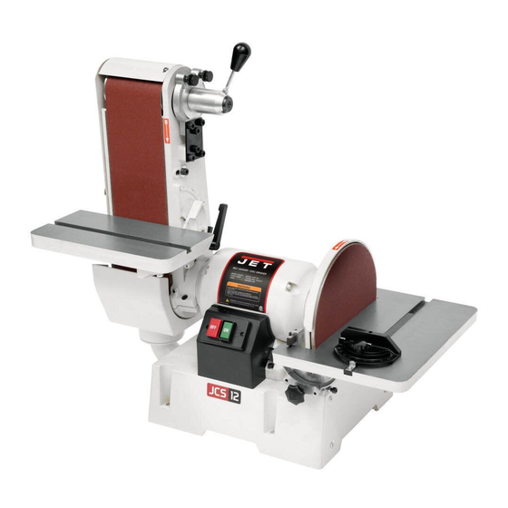
Combination Belt/Disc Sander
Model JSG-6DC
with optional open stand
with optional closed stand
for models with serial no. 20050451 and higher
JET
427 New Sanford Road
Part No. M-708599
LaVergne, Tennessee 37086
Revision H 05/2020
Ph.: 800-274-6848
ECR 200515104020
www.jettools.com
Copyright © 2014 JET
Advertisement
Table of Contents

Related Manuals for Jet JSG-6CS


Summarization of Contents
Warranty and Service
Warranty Period
Describes warranty durations for products and accessories.
Who is Covered
Specifies the warranty applies to the initial purchaser only.
What is Covered
Details defects covered and limitations like misuse or wear.
Warranty Limitations
Explains how commercial/industrial use affects warranty.
How to Get Technical Support
Provides contact information for technical support and service.
More Information
Directs users to distributors or website for product updates.
How State Law Applies
Mentions legal rights are subject to applicable state law.
Limitations on This Warranty
Covers exclusion of implied warranties and damages.
Product Listing with Warranty Period
Lists specific products and their respective warranty durations.
Warnings
General Safety Instructions
Covers reading manual, labels, training, work area, and personal safety.
Warnings
Operating Precautions
Covers tool maintenance, workpiece support, handling debris, and unattended operation.
California Proposition 65 Warnings
Alerts users to chemical exposures from wood dust and lead.
Safety Notice Symbols
Explains the meaning of Caution and Warning symbols used in the manual.
Introduction
Manual Purpose and Scope
Explains the manual covers operation, maintenance, and safety for the JSG-6DC.
Specifications
Model and Stock Numbers
Identifies the product model and associated stock keeping units.
Belt Section Specifications
Details dimensions, tilt, speed, and stops for the belt sanding component.
Disc Section Specifications
Details dimensions, tilt, speed, and stops for the disc sanding component.
General Specifications
Includes overall dimensions, footprint, and weight of the sander.
Accessory Stands Specifications
Lists approximate weights for optional open and closed stands.
On/Off Switch Padlock
Padlock Feature
Explains the switch accepts a padlock for safeguarding against unauthorized operation.
Locking Procedure
Provides step-by-step instructions on how to use the padlock feature.
Grounding Instructions
Electrical Connection Safety
Emphasizes qualified electricians and proper grounding to prevent shock.
Grounding Conductor Identification
Describes the equipment-grounding conductor's appearance (green with/without yellow stripes).
Extension Cords for Grounding
Specifies using 3-wire cords with grounding plugs for safety.
115 Volt Operation
Wiring for 115V
Describes the factory wiring and plug configuration for 115V operation.
Temporary Adapters
Explains the use and limitations of temporary adapters for grounded outlets.
Recommended Circuit
Advises on a dedicated 30 amp circuit for 115V operation.
230 Volt Operation
Wiring Conversion
Details steps to reconfigure motor leads for 230V operation.
Plug Replacement
Instructs to replace the 115V plug with a 230V compatible one.
Outlet Configuration
Specifies matching the 230V plug to the outlet configuration.
Recommended Circuit
Advises on a dedicated 15 amp circuit for 230V operation.
Extension Cords
Cord Sizing Guide
Provides a chart for selecting the correct gauge extension cord based on voltage and amperage.
Unpacking
Damage Inspection
Instructs to check for shipping damage and report it immediately.
Contents of Main Carton
Lists all parts included in the main sander package with reference to Figure 8.
Optional Accessory: Closed Stand
Contents of Closed Stand Carton
Lists parts for the optional closed stand with reference to Figure 9.
Optional Accessory: Open Stand
Contents of Open Stand Carton
Lists parts for the optional open stand with reference to Figure 10.
Assembly
Tools Required
Lists tools needed for assembly: hex keys, wrenches, sockets.
Lifting and Positioning
Provides safety warnings and instructions for moving the heavy machine.
Securing the Machine
Details how to bolt the sander firmly to a workbench or stand.
Surface Preparation
Instructs to clean factory-applied protectant from metal surfaces.
Disc Table
Attaching the Disc Table
Describes the steps to mount the disc table to the trunnion holder.
Belt Table
Mounting the Belt Table
Instructions for attaching the belt table trunnion and lock handle.
Installing Belt Tensioning Handle
Steps to attach the belt tensioning handle to the tracking assembly.
Installing Abrasives
Abrasive Disc Installation
Steps to apply the abrasive disc to the sanding disc, ensuring proper adhesion.
Installing Abrasives
Abrasive Belt Installation
Instructions for installing the abrasive belt, including checking directionality.
Workstop Assembly
Installing the Workstop
Describes how to attach the workstop assembly to the machine.
Dust Collection
Dust Collection Recommendation
Advises on connecting a dust collection system and its minimum capacity.
Adjustments
Tools Required
Lists tools needed for performing adjustments.
Belt Table Adjustment
Detailed steps for squaring the belt table to the platen.
Adjusting 90° Stop
How to set the 90-degree stop for the belt table.
Adjusting 45° Stop
How to set the 45-degree stop for the belt table.
Adjustments
Belt Arm Orientation
How to adjust and secure the belt arm position to vertical or horizontal.
Limit Screw Adjustment
How to adjust screws that limit the belt arm's rotation range.
Disc Table Adjustment
Steps to square the disc table to the disc and ensure parallelism.
Adjusting 90° Stop
How to set the 90-degree stop for the disc table.
Adjustments
Adjusting 45° Stop
How to set the 45-degree stop for the disc table.
Adjust Rear Stop
How to set or remove the rear stop for disc table tilt limits.
Miter Gauge Calibration
Instructions for setting the zero point of the miter gauge and checking parallelism.
Belt Tracking Adjustment
Tracking Procedure
Detailed steps for adjusting belt tracking using screws and handle.
Belt Replacement
Procedure
Steps to remove and install a new abrasive belt.
Abrasive Disc Replacement
Procedure
Steps to remove and install a new abrasive disc.
Maintenance
General Cleaning
Instructions for cleaning the machine after each use.
Periodic Inspections
What to check during regular maintenance for fastener tightness and wear.
Long-Term Storage
Advice on storing the machine for extended periods to prevent belt stretching.
Power Cord Care
Warning about worn or damaged power cords and immediate replacement.
Troubleshooting
Common Issues and Remedies
Lists common problems like no start, slow speed, vibration, and their solutions.
Optional Accessories
Accessory Identification
Lists stock numbers for optional stands (Open and Closed).
Replacement Parts
Ordering Information
How to order replacement parts and contact the service department.
Closed Stand Assembly (Optional)
Parts List: Closed Stand Assembly
Lists components for the optional closed stand assembly with index numbers.
Hardware for Sander Attachment
Lists hardware required for attaching the sander to the closed stand.
Open Stand Assembly (Optional)
Parts List: Open Stand Assembly
Lists components for the optional open stand assembly with index numbers.
Hardware for Stand Assembly
Lists hardware required for assembling the open stand.
Electrical Connections
230V Wiring Diagram
Shows the motor wiring configuration for 230V operation.
115V Wiring Diagram
Shows the motor wiring configuration for 115V operation.
Need help?
Do you have a question about the JSG-6CS and is the answer not in the manual?
Questions and answers