
Related Manuals for Alpha Technologies CFR 1500


Summary of Contents for Alpha Technologies CFR 1500
- Page 1 Operator’s Manual Alpha CFR 1500, CFR 2000, CFR 2500, and CFR 3000 U N I N T E R R U P T I B L E P O W E R S U P P L I E S...
- Page 2 Operator’s Manual Alpha CFR 1500, CFR 2000, CFR 2500, and CFR 3000 U N I N T E R R U P T I B L E P O W E R S U P P L I E S...
-
Page 3: Save These Instructions
IMPORTANT SAFETY INSTRUCTIONS CONTAINED IN THIS MANUAL CAUTION RISK OF ELECTRICAL SHOCK CAUTION: To reduce the risk of electrical shock, and to ensure the safe operation of this unit, the following symbols have been placed throughout the manual. Where these symbols appear, servicing should be performed only by qualified personnel. -
Page 4: The Alpha Cfr
Carefully unpack the unit. Report any shipping damage immediately. Please read the operators manual. If you have any questions regarding the safe installation of the unit, contact Alpha Technologies. The unit should be serviced only by qualified personnel. The unit contains more than one live circuit. Even though AC is not present at the input, it may be present at the output. - Page 5 THE ALPHA CFR IMPORTANT SAFETY PRECAUTIONS The CFR 1500-3000 Series units contain sealed, Lead-Acid batteries consisting of: Four batteries, six cells each, 48 VDC total. WARNING: Batteries contain high energy and chemical hazards. Carefully read this manual regarding safe battery handling, maintenance and disposal instructions.
-
Page 6: Table Of Contents
The Alpha CFR Table of Contents The Alpha CFR 1500, CFR 2000, CFR 2500, and CFR 3000 Uninterruptible Power Supplies INTRODUCTION ..............1 1.1 The Alpha CFR ............1 1.2 The CFR Advantage ............. 2 1.3 Unpacking and Inspection ..........4 FEATURES ................. - Page 7 The Alpha CFR Table of Contents, continued OPERATION, continued 4.2 Using the Standard Interface Device ......28 UPS Powering Up Output Shutdown Pending Output Shutdown in Progress Line Present Operation Line Failure (AC Input Out of Tolerance) Line Failure Operation Line Synchronization Low Battery Warning Low Battery Shutdown...
-
Page 8: Introduction
With distribution networks and service centers located throughout the world, Alpha Technologies is here to back you up. From your date of purchase, Alpha provides complete technical support and prompt, reliable service to ensure that your CFR-UPS provides you with a lifetime of reliable operation. -
Page 9: The Cfr Advantage
1. INTRODUCTION 1.2 The CFR Advantage ADVANCED POWER PROTECTION TECHNOLOGY Power protection devices can be judged by the type and quality of power they provide. Alpha CFR Uninterruptible Power Supplies provide continuous, conditioned “computer-grade” AC power to electronic equipment such as Computer Systems, Point of Sale Terminals, Process Controls, Telecommunications, Cable TV Headend, Broadband LAN, Manufacturing Control Systems, Critical Care and Hospital Lab Equipment. - Page 10 VDE, the Alpha CFR UPS is one of the safest, most reliable and versatile uninterruptible power supplies available. Our commitment to safety and quality engineering has not only established industry-wide safety standards, but has earned Alpha Technologies international recognition as a leader in power protection equipment.
-
Page 11: Unpacking And Inspection
1.3 Unpacking and Inspection Carefully remove the UPS from its shipping container. Inspect the contents. If items appear to be damaged or missing, contact Alpha Technologies and the shipping company immediately. Most shipping companies have only a short claim period. Make sure the following items have been included: 1. -
Page 12: Features
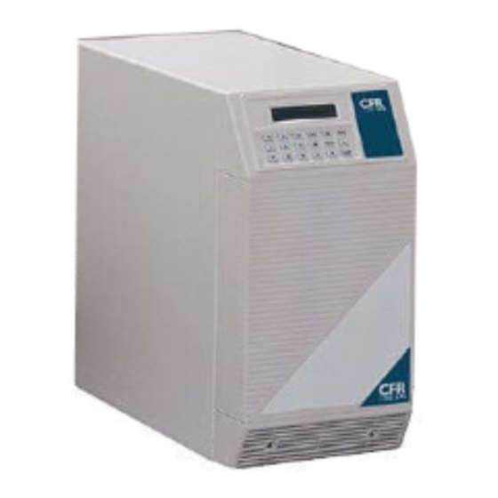
2. FEATURES 2.1 A Tour of the CFR The Alpha CFR is designed to be easy to use and extremely flexible. The CFR’s interchangeable front panel interface devices provide you with a wide range of information management options. The rear panel accepts a variety of connectors and receptacle plates to facilitate your most demanding communication and powering needs. -
Page 13: Cfr Rear Panel
2. FEATURES 2.3 CFR Rear Panel 1. AC LINE Cord The UPS is equipped with a standard, grounded AC line cord. 2. EXTERNAL BATTERY Connector The connector accepts a standard plug from the EBP Series Battery Pack. Extending backup time is as simple as plugging in the battery pack. 3. - Page 14 The load (equipment to be protected) connects to the rear panel output receptacles. Styles vary depending upon country, frequency and voltage. 13. AC OUTPUT Circuit Breaker The resettable breaker provides addional output protection to the load. Fig. 2 CFR 1500, CFR 2000, CFR 2500, and CFR 3000 Rear Panel...
-
Page 15: Information Management Options
2. FEATURES 2.4 Information Management Options Standard Interface Device The Standard Interface Device provides you with vital UPS operating parameters from front panel LEDs (see section 4.2). The Standard Interface also has a load indicator to help you determine precise loading on your UPS, plus Manual Start and Alarm Off switches. -
Page 16: Intelligent Interface Device
2. FEATURES 2.4 Information Management Options, continued Intelligent Interface Device (optional) The Intelligent Interface Device (IID) option is available either as a replacement of the Standard Interface Device (SID) or as a desktop unit for remotely accessing the unit (up to 2000 ft.). The desktop unit comes with an optional modem for accessing the UPS information via a telephone line. -
Page 17: Communication / Interface Options
For a full description of the features and capabilities of AlphaNet C shutdown software, refer to its user’s manual or contact Alpha Technologies. AlphaNet C is available for all major network platforms and operating systems — Novell Netware, SCO Unix, IBM OS/2, IBM AIX, Sun Solaris, Hewlett-Packard HP-UX (DAT), and Digital Equipment (OS/F, VMS, and DECNET). -
Page 18: Rear Panel Connectors
2. FEATURES 2.5 Communication / Interface Options, continued Rear Panel Connectors: Below are the various communication connectors as they appear on the back of the CFR-UPS. The photographs show the pin numbering for the different connector types. NOTE: Use only fully shielded cables to make connections to any of the DE-9 connectors (RS-232 port or LAN interface). -
Page 19: Rs-232 Connector
2. FEATURES 2.5 Communication / Interface Options, continued RS-232 Connector: The connection/specifications for the RS-232 serial port vary depending on the installed interface device (i.e., SID or IID option). RS-232 connection for the standard CFR-UPS (with SID or internal IID display) The standard CFR-UPS configuration with SID or internal IID connects to a computer or terminal using a standard straight-through RS-232 cable. - Page 20 2. FEATURES 2.5 Communication / Interface Options, continued RS-232 Connections with desktop IID: With the desktop IID the cable connecting the computer or terminal to the UPS is a nonstandard type. Fig. 7 CFR-UPS RS-232 Connector 2 Tx 3 Rx 5 Gnd 7 RTS 8 CTS...
-
Page 21: Lan Interface Connector
Basic UPS monitoring software is provided as part of many operating systems and can also be purchased from third party vendors. Alpha Technologies “AlphaNet C shutdown software” can also operate in the basic mode to shutdown the CFR before its battery reserve is exhausted. Refer to AlphaNet C Shutdown Software User’s Manual or contact Alpha Technologies for... -
Page 22: External Iid Connector
2. FEATURES 2.5 Communication / Interface Options, continued External IID Connector The external IID connector provides an interface for the optional desktop Intelligent Interface Device (IID). This allows the CFR to be remotely monitored and controlled from up to 2,000 feet away. The port uses a proprietary RS-485 protocol and has the following pin out: Pin 1 1: +12V DC (unreg) - Page 23 2. FEATURES 2.5 Communication / Interface Options, continued External Alarms Connector, continued Pin out: (RJ-45 connector, centered key) Pin 1 Low Battery Warning Line Present Pin out: (RJ-45 connector, Female) Line Failure N.C. LINE FAIL, COM contact LINE FAIL, N. C. contact LINE FAIL, N.
-
Page 24: Installation
This would discharge the UPS batteries and cause the output load to fail. Alpha Technologies recommends using a generator equipped with an electronic speed and voltage control. If a generator equipped with a mechanical governor "speed control"... -
Page 25: Connecting The Cfr
3. INSTALLATION 3.2 Connecting the CFR (Plug & Receptacle) 1. Connect a dedicated ground wire from the GROUND lug on the back of the CFR to an electrical ground point (i.e., wall receptacle gound or a copper water pipe). The wire size must be at least 12 AWG (3mm NOTE: Most electrical codes require this type of ground connection in case the AC line power cord is disconnected from the wall. -
Page 26: 1Terminal Block Input And Output
Pounds Meters 1500-2500 (60Hz) 3000 (60Hz) 2000-3000 (50Hz) Receptacle AC LINE Circuit Breaker BATTERY Circuit Breaker GROUND Lug Leveling Feet (CFR 3000 only) AC LINE Power Cord Fig. 10 CFR 1500, CFR 2000, CFR 2500, and CFR 3000 Rear Panels... -
Page 27: Terminal Block Input And Output Wiring
3. INSTALLATION 3.2.1 Terminal Block Input and Output Wiring CFR 1500, CFR 2000, CFR 2500 and CFR 3000 Terminal Block Input Frequency Voltage* 60Hz 120VAC 120VAC Neutral 50Hz 230VAC 230VAC Neutral 60Hz 208VAC Ø1 Ø2 60Hz 240VAC Ø1 Ø2 WARNING: Overcurent protection for the AC output circuit must be... -
Page 28: External Battery Pack
UPS. Secure the connector to the UPS using the Phillips screw #1. 4. Switch the EBP and CFR “BATTERY” breakers ON and test the unit for proper operation. BATTERY Circuit Breaker External Battery Connector Phillips Screws Fig. 11 CFR 1500, CFR2000, CFR 2500, and CFR 3000 with EBP External Battery Packs... -
Page 29: 208Vac/240Vac Configurations
Terminal block output, wherever possible, connect all 120V loads to L1 (not L2). If 120 V loads are connected to L2, do not exceed the current listed in Table 3. .1. Model Maximum current on L2 CFR 1500 7.2A CFR 2000 9.6A CFR 2500 12.0A... - Page 30 3. INSTALLATION 3.4 208 VAC vs 240 VAC (60 Hz) Configurations Since loads are shared, it is possible to exceed the rated maximum output current of one of the transformer windings, without actually exceeding the rated output current of the CFR-UPS. Therefore, careful consideration must be given as to how the loads connected to the CFR are to be divided.
- Page 31 3. INSTALLATION 3.4 208 VAC vs 240 VAC (60 Hz) Configurations, cont’d. 240VAC 32VAC 208VAC 120VAC 88VAC 88VAC 240VAC Neutral 208VAC 120VAC 120VAC Fig. 12 208 VAC Output Schematic (for reference only) Fig. 13 120/120/240 VAC Power distribution through L1 and L2 Fig.
-
Page 32: Operation
4. OPERATION 4.1 Start-up and Test Plug the CFR’s AC line cord into a wall receptacle or turn the AC Input circuit breaker ON. The TEST LED and OUTPUT LOAD display LEDs will flash for a few seconds to indicate the CFR is powering up. The LINE PRESENT LED will then come ON to indicate the AC input line is OK and the CFR is running on AC line power. -
Page 33: Manual Self-Test
4. OPERATION 4.1 Start-up and Test Manual Self-test Press (and hold for several seconds) the “MANUAL START” switch, located on the Standard Interface Panel, when the UPS is running on AC line power (“LINE PRESENT” LED ON). The unit will test the backup capabilities of the UPS for approximately one minute (“TEST”... -
Page 34: Switching Off The Ups
4. OPERATION 4.1 Start-up and Test, continued Switching OFF the UPS: Switch all equipment connected to the UPS OFF. Switch the rear panel “BATTERY” circuit breaker OFF. This will prevent the UPS from initiating LINE FAILURE operation when AC power is removed. -
Page 35: Using The Standard Interface Device
4. OPERATION 4.2 Using the Standard Interface Device The Standard Interface Device displays vital UPS operating parameters and has the ability to self-test the UPS at the touch of a button. When used in conjunction with the CFR's rear-panel “Form-C” contact closures, UPS status information can be sent directly to a Local Area Network (see section 2.5). -
Page 36: Ups Powering Up
4. OPERATION 4.2 Using the Standard Interface Device UPS Powering Up Whenever the CFR is powering up, the TEST LED flashes for a few seconds. At the same time the OUTPUT LOAD indicator LEDs flash in a chasing pattern to indicate that there is no output. -
Page 37: Line Present Operation
4. OPERATION 4.2 Using the Standard Interface Device, continued Line Present Operation The green “LINE PRESENT” LED indicates that the UPS is running on AC line (utility / mains) power. Fig.19 Line Failure (AC Input Out of Tolerance) Whenever AC line voltage becomes unacceptably high or low (+10 % / 25%), or the line frequency exceeds + 3%, the "LINE PRESENT"... -
Page 38: Low Battery Warning
4. OPERATION 4.2 Using the Standard Interface Device, continued Low Battery Warning The red “LOW BATTERY WARNING” LED precedes “LOW BATTERY SHUT- DOWN” by 2 to 5 minutes and indicates that the batteries can no longer support the load. Immediate steps should be taken to begin an orderly system shutdown. From LOW BATTERY WARNING, it may take several hours to fully recharge the batteries. -
Page 39: Alarm Off Switch
4. OPERATION 4.2 Using the Standard Interface Device, continued Alarm Off Switch The switch cancels the audible LOW BATTERY WARNING alarm. The alarm remains disabled until line power is restored and the batteries are recharged. ALARM OFF Switch Fig. 27 Manual Start / ( old to Test) Switch The switch is used to start the UPS from battery power whenever AC line power is not available (“LINE PRESENT”... -
Page 40: Rs-232 Terminal Communication
AC line which may be PRESENT; FAILURE; or TEST MODE. The ALARMS message lists all current alarms. For a complete description of alarms refer to section 5.12. Alpha Technologies - CFR CFR-UPS Micro Micro Serial#00000000 Serial No. -
Page 41: Rs-232 Menu Selection Icons
5. RS-232 TERMINAL COMMUNICATION 5.2 RS-232 Menu Selection Icons Icons have been placed throughout this section to easily guide you to key commands using remote terminal emulation. The icons provide short cuts to desired display screens without having to step through various menus. To use the icons, simply enter the number contained in the icon screen while you are in the terminal emulation mode. -
Page 42: Remote Terminal Quick Reference
5. RS-232 TERMINAL COMMUNICATION 5.3 Remote Terminal Quick Reference The menu items outlined in this manual can be accessed from a remote terminal. The numbers contained in this guide act as a quick reference to accessing menu functions. Single-digit numbers relate to specific main menus. Double-digit numbers relate to specific sub-menus. -
Page 43: Menu Commands Overview
5. RS-232 TERMINAL COMMUNICATION 5.4 Menu Commands Overview Overview The following section provides a general overview of the menu structure and gives some examples of how to perform certain command functions such as testing the UPS. Querying CFR Status and Measured Parameters The current status (mode of operation) of the CFR and all active alarms are displayed at the end of the opening menu (see section 5.12 for a list of status messages and alarm events). -
Page 44: System Parameters
5. RS-232 TERMINAL COMMUNICATION 5.4 Menu Commands Overview, continued Calibrating the CFR The CFR-UPS may be calibrated using two sets of parameters - Maintenance Parameters (commands “70” to “79”) and Service Parameters (commands “80” to “89”). Maintenance parameters allow you to customize the CFR detection and warning levels. -
Page 45: Input Parameters
5. RS-232 TERMINAL COMMUNICATION 5.6 Input Parameters “INPUT PARAMETERS” provides UPS Input Voltage, Current, Volt Amps, Power in Watts, Power Factor, and Line Frequency information. Voltage The voltage measured at the input of the UPS (i.e., 120 VAC). Current The flow of current measured at the input of the UPS (i.e., 3.1 Amps). Volt Amps The apparent input power of the UPS as calculated by multiplying the input voltage by the input current (i.e., 663 VA). - Page 46 5. RS-232 TERMINAL COMMUNICATION 5.7 Output Parameters, continued Current Output Current #1 displays the true RMS current on N. If there are no 120 V loads connected to N-L2, then this current represents the 120 V loads on N-L1 plus any equipment connected to the 120 V output receptacles.
-
Page 47: Battery Parameters
5. RS-232 TERMINAL COMMUNICATION 5.8 Battery Parameters “BATTERY PARAMETERS” provides UPS Battery Voltage, Charger Current, and Charger Status information. Voltage Voltage indicates the average DC voltage of UPS batteries. When the UPS is running in “LINE PRESENT” mode and the batteries are charged, the voltage will be approximately 27.6 VDC (equal to the charger’s “FLOAT”... - Page 48 5. RS-232 TERMINAL COMMUNICATION 5.9 User Parameters, continued When the CFR receives a “Start Shutdown” command (menu item 502), it waits for the period that is specified in the “Output Shutdown Delay” (menu item 505) and then shuts down its output. The CFR will remain in the shutdown mode for the time specified in the “Output Shutdown Duration”...
- Page 49 5. RS-232 TERMINAL COMMUNICATION 5.9 User Parameters, continued Set User Security Code The security code is used to restrict entry into certain areas of the program. The code (1111) is preset at the factory and allows access to USER PARAMETERS and HISTORY programs. The security code can be changed using the number keys on the keypad.
- Page 50 5. RS-232 TERMINAL COMMUNICATION 5.9 User Parameters, continued Cancel Output Shutdown This command cancels any pending or current UPS output shutdown. This command requires the USER SECURITY CODE. Recover Output Shutdown Only When AC Line Restored (xxx) xxx=“Yes” or “No”, (Default value is “Yes”) This command determines when the CFR restores output power after a output shutdown.
- Page 51 5. RS-232 TERMINAL COMMUNICATION 5.9 User Parameters, continued Disable Transmission of Unsolicited Alarms “509 None (xxxx)”; xxxx= “active” or blank; default is “active.” Setting this option to “active” disables the transmission of all unsolicited alarm messages. USER SECURITY CODE is required to set this option.
-
Page 52: Maintenance Parameters
5. RS-232 TERMINAL COMMUNICATION 5.10 Maintenance Parameters “MAINTENANCE PARAMETERS” allow you to customize UPS detection and warning characteristics. Normally, there should be no need to change these factory settings. CAUTION: If any of these parameters are changed, it is vital to thoroughly test the UPS since an improper adjustment can render the unit useless. - Page 53 5. RS-232 TERMINAL COMMUNICATION 5.10 Maintenance Parameters, continued Slow Detect Hi Ref Increasing this value will make the UPS more sensitive to a slow, high amplitude line disturbance (sustained overvoltage) by lowering the overvoltage detection level. NOTE: The Slow Detect Hys Hi Ref should also be adjusted by the same amount.
-
Page 54: Parameter Dump Command
5. RS-232 TERMINAL COMMUNICATION 5.11 Parameter Dump Command (Function 0) Parameter Dump Command (Function 0) Function ‘0’ displays all UPS parameters in the following format: #####,###.#,#####,#####,##.##,###.#,#####,###.#,#####,###.#,#####,#####,##.##, ###.#,###.#,###.#,xxxxx,#####,#####,#####,#,##,##,##,##,##,##,##,##, ###############,############ <CR> <LF> Where ‘#’ indicates a digit or a blank character and ‘x’ represents a letter. -
Page 55: Event Descriptions
5. RS-232 TERMINAL COMMUNICATION 5.12 Event Descriptions (Alarms) There are 6 alarm groups which upon activation will be displayed at the end of the opening menu. These are: INPUT: BATTERY: OUTPUT: ENVIRONMENTAL: SERVICE1: SERVICE2: The following lists the mnemonics and description for each alarm group: INPUT: FREQ_LO - input line frequency low... - Page 56 5. RS-232 TERMINAL COMMUNICATION 5.12 Event Descriptions (Alarms), continued Several alarms can be triggered during the same event. If there is a loss of AC line voltage, for example, the UPS may detect a glitch, low frequency and blackout. Low Battery Warning (LO_BAT_WARN) - The batteries are near the end of their useful charge.
- Page 57 5. RS-232 TERMINAL COMMUNICATION 5.12 Event Descriptions, continued Blackout (BLACKOUT) - The blackout alarm is triggered when the input voltage is lost for 12 ms, or when the RMS input voltage is less than 1/2 the nominal voltage for 100 ms or longer. * * Frequency High (FREQ_HI) - A frequency high alarm is triggered when there is a power line problem where the input frequency increases beyond the preset limit.
- Page 58 5. RS-232 TERMINAL COMMUNICATION 5.12 Event Descriptions, continued Input Line Fail - Indicates that the UPS switched to backup power to protect the equipment for one (or more) of the above conditions. * * Normal Line Mode - Indicates that the UPS is drawing power from the AC line and charging the batteries.
-
Page 59: Rs-232 Terminal Setup
5. RS-232 TERMINAL COMMUNICATION 5.13 RS-232 Terminal Setup Terminal Emulation Setup If you are using a terminal emulation software (such as PROCOMM) to communicate with the CFR, use the following setup: Emulation Type: VT100 or compatible Duplex Mode: Half Duplex Xon/Xoff Flow Control: SID: ON, IID: OFF RTS/CTS Flow Control:... -
Page 60: Maintenance
6. MAINTENANCE 6.1 CFR Maintenance The electronic components used in the UPS require no maintenance. If the unit fails to perform a specific function, refer to the troubleshooting guide. The guide lists typical symptoms, causes and solutions that apply to the UPS, starting with the most obvious and working systematically through the unit. -
Page 61: Battery Testing
Switch the load ON, one device at a time. To determine recharge time, subtract the time you resumed LINE PRESENT operation from when the “LOW BATTERY WARNING” LED goes OFF. Fig. 35 - Standard Interface Device ALPHA TECHNOLOGIES 05-07-96 08:02:10 LINE PRESENT... -
Page 62: Removing The Cfr Front Panel And Cover
6. MAINTENANCE 6.4 Removing the CFR Front Panel and Cover CAUTION: INTERNAL MAINTENANCE SHOULD BE SERVICED ONLY BY QUALIFIED PERSONNEL. 1. Disconnect all loads from the OUTPUT receptacles on the UPS. 2. Switch the rear panel BATTERY circuit breaker OFF. 3. -
Page 63: Internal Battery Replacement
WARNING: Do not short out battery terminals. Batteries should be inspected every year for signs of cracking, leaking, or swelling. Always replace batteries with those of an identical type and rating. Never install old or untested batteries. Contact Alpha Technologies to order and recycle batteries. - Page 64 6. MAINTENANCE 6.5 Internal Battery Replacement, continued CFR 1500, CFR 2000(E), CFR 2500(E) Internal Battery Replacement Procedure. IMPORTANT: READ THE SAFETY PRECAUTIONS LOCATED AT THE FRONT OF THE MANUAL BEFORE PROCEEDING. NOTE: All references to left and right are made facing the front of the CFR 1.
- Page 65 6. MAINTENANCE 6.5 Internal Battery Replacement, continued CFR 3000(E) Internal battery replacement procedure IMPORTANT: READ THE SAFETY PRECAUTIONS LOCATED AT THE FRONT OF THE MANUAL BEFORE PROCEEDING. NOTE: All references to left and right are made facing the front of the CFR 1.
-
Page 66: Troubleshooting Guide
6. MAINTENANCE 6.6 Troubleshooting Guide SYMPTOM CAUSE REMEDY No Output Power: Utility power outage; "LINE PRESENT" OFF "LINE FAILURE" OFF AC power cord Plug in AC power cord. unplugged; AC input circuit breaker Reset breaker. OFF. BATTERY circuit Reset breaker. breaker OFF. - Page 67 6. MAINTENANCE 6.6 Troubleshooting Guide SYMPTOM CAUSE REMEDY No Output Power: Utility power outage; "LINE PRESENT" OFF "LINE FAILURE" OFF AC power cord Plug in AC power cord. unplugged; AC input circuit breaker Reset breaker. OFF. BATTERY circuit Reset breaker. breaker OFF.
- Page 68 6. MAINTENANCE 6.6 Troubleshooting Guide, continued SYMPTOM CAUSE REMEDY No output voltage Battery voltage below Wait for line power to during utility outage: low voltage cutout return and recharge "LINE PRESENT" OFF (after long outage). batteries. "LINE FAILURE" OFF "LOW BATTERY Battery voltage below Wait for batteries to SHUTDOWN"...
-
Page 69: Troubleshooting Using The Sid
6. MAINTENANCE Troubleshooting Using the SID The OUTPUT LOAD LEDs, located on the front panel of the Standard Interface Device, are designed to display UPS fault conditions once the unit has detected an internal problem, indicated by the SERVICE LED. This information provided by the LEDs is extremely useful during troubleshooting and maintenance. - Page 70 6. MAINTENANCE Troubleshooting Using the SID, continued SYMPTOM CAUSE REMEDY OVERLOAD LED (ON) Fast Detector / Low Call Alpha. SERVICE LED (ON) Sensitivity Fault. ALARM OFF switch pressed and held: 100% LED (Flashing) PLL Fault. Wait for line power to SERVICE LED (ON) Instability in line freq return.
-
Page 71: Repair Instructions
6. MAINTENANCE 6.8 Repair Instructions Before returning a unit to Alpha Technologies for repair, a Return Material Authoriza- tion (RMA) should first be obtained from Alpha's Customer Service Department. The RMA number should be clearly marked on the unit’s original shipping container. If the original container is no longer available, the UPS should be packed with at least 3 inches of shock- absorbent material. -
Page 72: Specifications
3:1 max., and a typical power factor of 0.75. Dimensions CFR 1500, 2000, 2500: ..8.5"W x 21.3”H x 22.5"D (216mm x 541mm x 571mm) CFR 3000: ......8.5"W x 21.3"H x 30"D... -
Page 73: Specifications
Valve regulated, maintenance-free Battery Voltage 48 VDC Batt. Low Volt. Cutout 39 VDC (>25% load), [42 VDC (<25% load)] Battery Recharge Time 5.0 hrs. for CFR 1500-2500 10 hrs. for CFR 3000 Charger Linear (3A max.) Charger Voltage 55.2 VDC at 25°C (adjustable) Operating Temp 32°-104°... -
Page 74: Warranty
The liability of Alpha Technologies under this warranty is solely limited to repairing, replacing, or issuing credit (at the discretion of Alpha Technologies) provided that: 1. Alpha Technologies is promptly notified in writing, or by telephone, that a failure or defect has occurred; UNITED STATES... -
Page 75: Important
EMERGENCY SHUTDOWN EMERGENCY SHUTDOWN IMPORTANT THE UPS CONTAINS MORE THAN ONE LIVE CIRCUIT. DURING AN EMERGENCY, UTILITY POWER MAY BE DISCONNECTED AT THE SERVICE ENTRANCE OR MAIN ELECTRICAL PANEL TO PROTECT EMERGENCY PERSONNEL; HOWEVER, POWER WILL STILL BE PRESENT AT THE UPS OUTPUT. TO PREVENT THE POSSIBILITY OF INJURY TO SERVICE OR EMERGENCY PERSONNEL, ALWAYS SWITCH THE UPS REAR PANEL BATTERY CIRCUIT BREAKER(S) OFF TO DE-... - Page 76 3307 Limassol, Cyprus Tel: +357–5–375675 Fax: +357–5–359595 AUSTRALIA Alpha Technologies 8 Anella Ave., Unit 6 Castle Hill, NSW 2154 Tel:+61(0)2 9894–7866 Fax:+61(0)2 9894–0234 http://www.alpha.com Alpha sales and service offices located throughout the world Printed in Canada 017–071–B0–002 4/96 © 1996 Alpha Technologies...
Need help?
Do you have a question about the CFR 1500 and is the answer not in the manual?
Questions and answers