Goodman A/GPG13 M SERIES W/R410A Installation & Operating Instructions Manual
A/gpg13 m series w/r410a single package gas-electric heating & cooling unit
Hide thumbs
Also See for A/GPG13 M SERIES W/R410A:
Table of Contents
Advertisement
Prior to installation, thoroughly familiarize yourself with this Installation Manual. Observe all safety warnings. During
It is your responsibility to install the product safely and to educate the customer on its safe use.
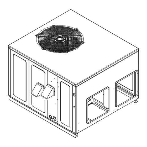
These installation instructions cover the outdoor
installation of single package gas electric heating and
cooling units. See the Specification Sheet or Technical
Manual applicable to your model* for information
regarding accessories.
IO-357D
11/12
INSTALLATION & OPERATING
INSTRUCTIONS for
A/GPG13 M SERIES W/R410A
SINGLE PACKAGE GAS-ELECTRIC
HEATING & COOLING UNIT
Affix this manual and Users Information Manual adjacent to the unit.
RECOGNIZE THIS SYMBOL AS A SAFETY PRECAUTION.
ATTENTION INSTALLING PERSONNEL
installation or repair, caution is to be observed.
Goodman Manufacturing Company, L.P.
5151 San Felipe, Suite 500, Houston, TX 77056
www.goodmanmfg.com - or - www.amana-hac.com
2009 - 2010, 2012 Goodman Manufacturing Company, L.P.
©
This Forced Air Central Unit Design Complies With
Requirements Embodied in The American National
Standard / National Standard of Canada Shown Below.
ANSI Z21.47•CSA-2.3 Central Furnaces
*NOTE: Please contact your distributor or
our website for the applicable
Specification Sheet or Technical Manual
referred to in this manual.
Advertisement
Table of Contents

Related Manuals for Goodman A/GPG13 M SERIES W/R410A


Summary of Contents for Goodman A/GPG13 M SERIES W/R410A
- Page 1 INSTALLATION & OPERATING INSTRUCTIONS for A/GPG13 M SERIES W/R410A SINGLE PACKAGE GAS-ELECTRIC HEATING & COOLING UNIT Affix this manual and Users Information Manual adjacent to the unit. This Forced Air Central Unit Design Complies With Requirements Embodied in The American National Standard / National Standard of Canada Shown Below.
-
Page 2: Table Of Contents
Index Replacement Parts ....................................3 ..................................... 3 RDERING ARTS Safety Instructions ....................................3 ........................3 MPORTANT OTE TO THE WNER REGARDING RODUCT ARRANTY Unit location ....................................... 4 : ....................................4 NSTALLATIONS : ................................4 ROUND EVEL NSTALLATIONS : ..................................5 OOFTOP NSTALLATIONS : ................................ -
Page 3: Replacement Parts
REPLACEMENT PARTS Keep this literature in a safe place for future reference. WARNING RDERING ARTS When reporting shortages or damages, or ordering repair O NOT CONNECT TO OR USE ANY DEVICE THAT IS NOT DESIGN CERTIFIED parts, give the complete unit model and serial numbers as BY GOODMAN FOR USE WITH THIS UNIT. -
Page 4: Unit Location
UNIT LOCATION WARNING O PREVENT POSSIBLE EQUIPMENT DAMAGE, PROPERTY DAMAGE, PERSONAL INJURY OR DEATH, THE FOLLOWING BULLET POINTS MUST BE OBSERVED WHEN INSTALLING THE UNIT. NSTALLATIONS • For proper flame pattern within the heat exchanger and proper condensate drainage, the unit must be mounted level. -
Page 5: Rooftop Installations Only
NSTALLATIONS • Sufficient structural support must be determined prior to locating and mounting the curb and package unit. • Ductwork must be constructed using industry guidelines. The duct work must be placed into the roof curb before mounting the package unit. •... -
Page 6: Transportation Damage
To assure that your unit operates safely and efficiently, it must be installed, operated, and maintained in accordance with these in- stallation and operating instructions, all local building codes and ordinances, or in their absence, with the latest edition of the Na- tional Fuel Gas Code NFPA54/ANSI Z223.1 and National Stan- dard of Canada CAN/CSA B149 Installation Codes. -
Page 7: Piping
IPING IMPORTANT NOTE: To avoid possible unsatisfactory operation or equipment damage due to under firing of equipment, do not un- dersize the natural/propane gas piping from the meter/tank to the unit. When sizing a trunk line, include all appliances on that line that could be operated simultaneously. -
Page 8: Propane Gas Installations
PROPANE GAS INSTALLATIONS Sizing Between First and Second Stage Regulator Maximum Propane Capacities listed are based on 1 PSIG Pressure Drop at 10 PSIG Setting. Capacities in 1,000 BTU/HR PIPE OR WARNING NOMINAL PIPE SIZE, TUBING TUBING SIZE, O.D., TYPE L SCHEDULE 40 LENGTH, FEET... -
Page 9: Unit Voltage
Movement of air must not be obstructed by furniture, door, draperies, etc. The thermostat must not be mounted where it CAUTION will be affected by drafts, hot or cold water pipes or air ducts in walls, radiant heat from fireplace, lamps, the sun, television, O PREVENT IMPROPER AND DANGEROUS OPERATION DUE TO WIRING ERRORS, etc. -
Page 10: Circulating Air And Filters
Down Discharge Applications Cut insulation around bottom openings and remove panels from the bottom of the unit, saving the screws holding the panels in place. NOTE: Single phase models require installation of horizontal duct kit #20464501PDGK (medium chassis) and #20464502PDGK (large chassis). UCTWORK Duct systems and register sizes must be properly designed for the C.F.M. -
Page 11: Venting
VENTING 2. The spark igniter and gas valve energizes for 7 seconds. NOTE: The igniter produces a very intense electrical spark that ignites the gas. NOTE: Venting is self-contained. Do not modify or block. 3. The 30-second HEAT FAN ON delay time begins. 4. -
Page 12: As Upply Ressure Easurement
8. Smell for gas, including near the ground. This is important WARNING because some types of gas are heavier than air. If you have waited five minutes and you do smell gas, immediately follow the warnings on page 3 of this manual. O AVOID PROPERTY DAMAGE, PERSONAL INJURY OR DEATH DUE TO FIRE OR EXPLOSION, A QUALIFIED SERVICER MUST INVESTIGATE THE REASON FOR If having waited for five minutes and no gas smell is noted,... -
Page 13: Gas Manifold Pressure Measurement And Adjustment
The line pressure supplied to the gas valve must be within the 8. Measure the gas supply pressure with burners firing. Adjust range specified in the chart on the next page. The supply pressure supply pressure using the Inlet Gas Supply Pressure table can be measured at the gas valve inlet pressure tap or at a hose shown below. -
Page 14: Limit Check
6. Turn ON power and close thermostat “R” and “W” contacts Temperature Rise Check to provide a call for heat. Check the temperature rise through the unit by placing 7. Using a leak detection solution or soap suds, check for thermometers in supply and return air registers as close to leaks at outlet pressure boss plug (Honeywell valve) or the unit as possible. -
Page 15: Cooling Startup
Adjust the thermostat setting below room temperature. All package units with fixed orifice devices are charged using 1. Main burners must go OFF. the super heat method at the compressor suction line. 2. Circulating Air Blower will continue to run for 120, 135 or After superheat is adjusted it is recommended to check unit 150 seconds, depending on the setting. -
Page 16: Abnormal Operation - Cooling
If flame is established but lost, the control will energize the A primary limit will open due to excessive supply air circulator blower at the heat speed and then begin a new temperatures. This can be caused by a dirty filter, excessive ignition sequence. -
Page 17: Cabinet Finish Maintenance
LEANING ASSAGES UALIFIED ERVICER ABINET INISH AINTENANCE 1. Shut off electric power and gas supply to the unit. Use a fine grade automotive wax on the cabinet finish to 2. Remove burner assembly by disconnecting the gas line maintain the finish’s original high luster. This is especially and removing the manifold bracket from the partition panel. -
Page 18: Cleaning Burners
ACCESSORIES AND FUNCTIONAL PARTS LEANING URNERS 1. Shut off electric power and gas supply to the unit. 2. Remove the screws securing the manifold to the burner HEET ETAL CCESSORIES retention bracket. Remove the manifold and rotate each Additional accessories can be purchased to fit specific application burner counterclockwise to remove. -
Page 19: Blower Performance Data/Single Phase
BLOWER PERFORMANCE DATA - SINGLE PHASE * P G 1 3 2 4 0 4 5 M 4 1 * * - R is e R a n g e : 3 0 ° - 6 0 ° U n it L O W M E D IU M H IG H... - Page 20 BLOWER PERFORMANCE DATA - SINGLE PHASE * P G 1 3 3 6 0 4 5 M 4 1 * * - R is e R a n g e : 3 0 - 6 0 ° U n it L O W M E D IU M H IG H...
- Page 21 BLOWER PERFORMANCE DATA - SINGLE PHASE *PG1348070M41** - Rise Range: 35° - 65° F T4 COOLING T5 COOLING T1 HEATING SPEED T2 HEATING SPEED T3 HEATING SPEED E.S.P SPEED SPEED CFM WATTS RISE WATTS RISE WATTS RISE WATTS WATTS 1088 1401 1624 1704...
- Page 22 BLOWER PERFORMANCE DATA - SINGLE PHASE *PG1360140M41** - Rise Range: 45° - 75° F T4 COOLING T5 COOLING T1 HEATING SPEED T2 HEATING SPEED T3 HEATING SPEED E.S.P SPEED SPEED CFM WATTS RISE WATTS RISE WATTS RISE WATTS WATTS 1100 1445 1762 1878...
- Page 23 BLOWER PERFORMANCE DATA - HEATING SPEEDS THREE PHASE GPG1336090M43A* - Rise Range: 45° - 75° Unit MEDIUM HIGH Static W ATTS RISE W ATTS RISE W ATTS RISE 1100 1469 1655 1037 1409 1579 1327 1483 1257 1407 1163 1329 1094 1210 1036...
- Page 24 BLOWER PERFORMANCE DATA - COOLING SPEEDS THREE PHASE G P G 1 3 3 6 * * * M 4 3 A * - C O O L IN G S P E E D S U n it H IG H ( C o o lin g S p e e d ) M E D IU M ( C o o lin g S p e e d ) L O W ( C o o lin g S p e e d ) S ta tic...
-
Page 25: Ignition Control Diagnostic Indicator Chart
IGNITION CONTROL DIAGNOSTIC INDICATOR CHART Light Signal Refer to Abnormal Heating or Cooling Operation Sections of this Manual Internal Control Failure 1 Flash External Lockout 2 Flashes Pressure Switch Stuck Open 3 Flashes Pressure Switch Stuck Closed 4 Flashes Thermal Protection Device Open 5 Flashes Flame Detected with Gas Valve Closed 6 Flashes... -
Page 26: Appendix
APPENDIX UNIT DIMENSIONS FLUE EXHAUST HOOD FLUE EXHAUST HEAT EXCHANGE ACCESS PANEL POWER WIRE ENTRANCE CONTROL WIRE ENTRANCE EXHAUST FLUE HOOD BLOWER ACCESS PANEL... -
Page 27: Wiring Diagrams
*PG13(24, 30, 36, 42)1A* WIRING DIAGRAM HIGH VOLTAGE! DISCONNECT ALL POWER BEFORE SERVICING OR INSTALLING THIS UNIT. MULTIPLE POWER SOURCES MAY BE PRESENT. FAILURE TO DO SO MAY CAUSE PROPERTY DAMAGE, PERSONAL INJURY OR DEATH. COMP CC L2 CH OPTIONAL CH OPTIONAL CONNECTED AT L1, L2 NOTE 3... - Page 28 *PG13(24, 30, 36, 42)1A* WIRING DIAGRAM HIGH VOLTAGE! DISCONNECT ALL POWER BEFORE SERVICING OR INSTALLING THIS UNIT. MULTIPLE POWER SOURCES MAY BE PRESENT. FAILURE TO DO SO MAY CAUSE PROPERTY DAMAGE, PERSONAL INJURY OR DEATH. SUPPLY VOLTAGE COMPONENT LEGEND 208-230/1/60 WIRE SPLICE ALS AUXILIARY LIMIT SWITCH NOTE 3...
- Page 29 *PG13(48, 60)1A* WIRING DIAGRAM HIGH VOLTAGE! DISCONNECT ALL POWER BEFORE SERVICING OR INSTALLING THIS UNIT. MULTIPLE POWER SOURCES MAY BE PRESENT. FAILURE TO DO SO MAY CAUSE PROPERTY DAMAGE, PERSONAL INJURY OR DEATH. COMP CH OPTIONAL CH OPTIONAL CONNECTED AT L1, L2 NOTE 3 POWER SUPPLY 208-230/1/60...
- Page 30 *PG13(48, 60)1A* WIRING DIAGRAM HIGH VOLTAGE! DISCONNECT ALL POWER BEFORE SERVICING OR INSTALLING THIS UNIT. MULTIPLE POWER SOURCES MAY BE PRESENT. FAILURE TO DO SO MAY CAUSE PROPERTY DAMAGE, PERSONAL INJURY OR DEATH. SUPPLY VOLTAGE COMPONENT LEGEND FACTORY WIRING 208-230/1/60 AUXILIARY LIMIT SWITCH LINE VOLTAGE NOTE 3...
- Page 31 *PG13(24, 30, 36, 42)1B* WIRING DIAGRAM HIGH VOLTAGE! DISCONNECT ALL POWER BEFORE SERVICING OR INSTALLING THIS UNIT. MULTIPLE POWER SOURCES MAY BE PRESENT. FAILURE TO DO SO MAY CAUSE PROPERTY DAMAGE, PERSONAL INJURY OR DEATH. Wiring is subject to change. Always refer to the wiring diagram on the unit for the most up-to-date wiring.
- Page 32 *PG13(24, 30, 36, 42)1B* WIRING DIAGRAM HIGH VOLTAGE! DISCONNECT ALL POWER BEFORE SERVICING OR INSTALLING THIS UNIT. MULTIPLE POWER SOURCES MAY BE PRESENT. FAILURE TO DO SO MAY CAUSE PROPERTY DAMAGE, PERSONAL INJURY OR DEATH. Wiring is subject to change. Always refer to the wiring diagram on the unit for the most up-to-date wiring.
- Page 33 *PG13(48, 60)1B* WIRING DIAGRAM HIGH VOLTAGE! DISCONNECT ALL POWER BEFORE SERVICING OR INSTALLING THIS UNIT. MULTIPLE POWER SOURCES MAY BE PRESENT. FAILURE TO DO SO MAY CAUSE PROPERTY DAMAGE, PERSONAL INJURY OR DEATH. Wiring is subject to change. Always refer to the wiring diagram on the unit for the most up-to-date wiring.
- Page 34 *PG13(48, 60)1B* WIRING DIAGRAM HIGH VOLTAGE! DISCONNECT ALL POWER BEFORE SERVICING OR INSTALLING THIS UNIT. MULTIPLE POWER SOURCES MAY BE PRESENT. FAILURE TO DO SO MAY CAUSE PROPERTY DAMAGE, PERSONAL INJURY OR DEATH. Wiring is subject to change. Always refer to the wiring diagram on the unit for the most up-to-date wiring.
- Page 35 GPG13(36)3** WIRING DIAGRAM HIGH VOLTAGE! DISCONNECT ALL POWER BEFORE SERVICING OR INSTALLING THIS UNIT. MULTIPLE POWER SOURCES MAY BE PRESENT. FAILURE TO DO SO MAY CAUSE PROPERTY DAMAGE, PERSONAL INJURY OR DEATH. T2 T1 COMP CH OPTIONAL CH OPTIONAL SEE NOTE 3 CONNECTED AT L1, L2 POWER SUPPLY NOTE 3...
- Page 36 GPG13(36)3** WIRING DIAGRAM HIGH VOLTAGE! DISCONNECT ALL POWER BEFORE SERVICING OR INSTALLING THIS UNIT. MULTIPLE POWER SOURCES MAY BE PRESENT. FAILURE TO DO SO MAY CAUSE PROPERTY DAMAGE, PERSONAL INJURY OR DEATH. SUPPLY VOLTAGE COMPONENT LEGEND FACTORY WIRING 208-230/3/60 LINE VOLTAGE AUXILIARY LIMIT SWITCH NOTE 3 LOW VOLTAGE...
- Page 37 GPG13(48, 60)3** WIRING DIAGRAM HIGH VOLTAGE! DISCONNECT ALL POWER BEFORE SERVICING OR INSTALLING THIS UNIT. MULTIPLE POWER SOURCES MAY BE PRESENT. FAILURE TO DO SO MAY CAUSE PROPERTY DAMAGE, PERSONAL INJURY OR DEATH. COMP CH OPTIONAL CH OPTIONAL CONNECTED AT L1, L2 NOTE 3 POWER SUPPLY 208-230/3/60...
- Page 38 GPG13(48, 60)3** WIRING DIAGRAM HIGH VOLTAGE! DISCONNECT ALL POWER BEFORE SERVICING OR INSTALLING THIS UNIT. MULTIPLE POWER SOURCES MAY BE PRESENT. FAILURE TO DO SO MAY CAUSE PROPERTY DAMAGE, PERSONAL INJURY OR DEATH. SUPPLY VOLTAGE COMPONENT LEGEND FACTORY W IRING 208-230/3/60 LINE VOLTAGE AUXILIARY LIMIT SWITCH...
-
Page 39: Minimum Clearances
MINIMUM CLEARANCES 48" MIN 12" MIN 3" 12" MIN 36" MIN (FOR SERVICE) NOTE: Roof overhang should be no more than 36". UNIT 2 Ton 2 1/2 Ton 3 Ton 3 1/2 / 4 Ton 5 Ton Min. Filter Size (1)20 x 20 x 1 (1)20 x 25 x 1 (1)25 x 25 x1 (2)20 x 20 x 1 (2)20 x 25 x 1 RECOMMENDED FILTER SIZES... - Page 40 PACKAGE UNITS - DUAL FUEL & GAS HOMEOWNER’S ROUTINE MAINTENANCE RECOMMENDATIONS We strongly recommend a bi-annual maintenance checkup be performed by a qualified service agency before the heating and cooling seasons begin. NNUAL NSPECTION UALIFIED ERVICER Your package unit should be inspected by a qualified installer, or service agency at least twice every year.
Need help?
Do you have a question about the A/GPG13 M SERIES W/R410A and is the answer not in the manual?
Questions and answers