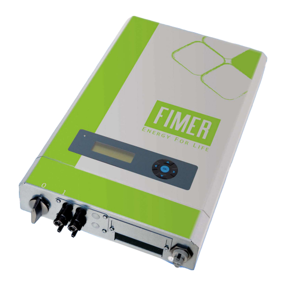
Summary of Contents for Fimer Series R25-R55
- Page 1 Grid connected PV Inverter series R25 Grid connected PV Inverter series R25- - - - R55 R55 R55 R55 Grid connected PV Inverter series R25 Grid connected PV Inverter series R25 Sensor Box and Yield Monitoring Module Guide...
- Page 2 ________________________________________________________________________________ _____________________________________________________________________________...
-
Page 3: Table Of Contents
Copyright– All rights reserved This publication is property of Fimer S.p.A. Any divulgation or reproduction of it as a whole or in part in forbidden unless expressly authorised. The contents, pictures and texts can be use for training the installers and the end users of the product. -
Page 4: Introduction
The sensor box is an optional accessory specifically designed to be used in conjunction with the R25-R35-R50-R55 inverters manufactured by Fimer , and it is marketed by Fimer. This document is a supplement to the User Manual for PV inverters. -
Page 5: Cabling Of Sensor
1). Button combination: ▲..►..▼..▲..►..▼ and complete by pressing [OK]. Further information with regard to controlling the inverter display can be found in the User Manual for Fimer’s 1-phase inverters. All parameters required for operating the sensor can be found under the main menu item "Environment"... -
Page 6: Setting The Module Temperature Of Sensor Box
________________________________________________________________________________ Value = 1 Si-01TC, Si-01TCext or Si-01TC-T from Mencke & Tegtmeyer (Sensor Box) connected 5.2 Setting the module temperature of Sensor Box Parameter number 211: Module-temperature sensor type of sensor Box Menu Environment Short description TYPTM Default Value Value = 0 no module temperature sensor connected Value = 1 PT1000 sensor connected Value = 2 Type LM35 temperature sensor (included in the Sensor Box) connected Parameter number 212: Ambient-temperature sensor type... -
Page 7: Option: Comparison Of Yields From Inverters By Sensor Box Module
Suitable installation position and geographical orientation for the sensor box (same inclination, orientation and shadowing as the modules) Activation code (available from FIMER for an additional charge) Note: The sensor and inverter data can be compared without the activation code. It is also possible to read out the annual sensor logger and the annual energy logger without the activation code. -
Page 8: Data Evaluation
DC output. If this value is overshot, an alarm is activated. Parameter number 283: Activation code for yield monitoring Menu Installation Monitoring Short Description Default value Enter the code given to you by FIMER. 7.4 Data evaluation Parameter number 220: Sensor output Menu Environment Short Description... -
Page 9: Annual Sensor Energy Logger
________________________________________________________________________________ Parameter number 219: Total yield of the sensor Menu Environment Short Description Unit Total yield meter of the sensor since its start-up. This meter displays the "sensor yield" calculated since start-up. It is used to compare the actual total yield (see parameter 12) with the theoretical "yield"... -
Page 10: Using Hyperterminal
________________________________________________________________________________ 8.1.2 Using HyperTerminal Read out the annual sensor energy logger using HyperTerminal and command /8. Entering command /9 displays the actual yield and the sensor yield at the same time.. 9 Alarm If the inverter detects a yield variation, it continues to function but an acoustic and a visual alarm signal are output. - Page 11 ________________________________________________________________________________ ________________________________________________________________________________...
- Page 12 _____________________________________________________________________________10...


Need help?
Do you have a question about the Series R25-R55 and is the answer not in the manual?
Questions and answers