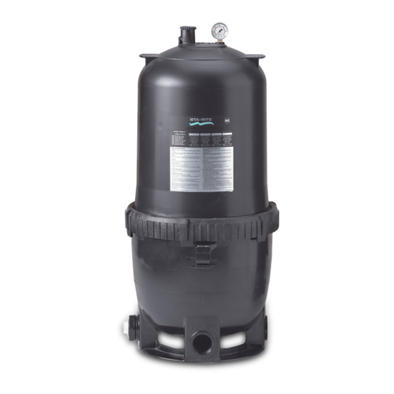
STA-RITE System 2 Owner's Manual
Modular media filters
Hide thumbs
Also See for System 2:
- Owner's manual (24 pages) ,
- Owner's manual (36 pages) ,
- Owner's manual (11 pages)
Advertisement
Table of Contents
- 1 Table of Contents
- 2 Safety Instructions
- 3 General Information
- 4 Specifications
- 5 Installation
- 6 Initial Startup
- 7 Filter Disassembly / Assembly
- 8 Module Cleaning Procedure
- 9 Special Cleaning Instruction
- 10 System Inspection/Winterizing
- 11 Troubleshooting Guide
- 12 Repair Parts List
- 13 Warranty Registration Card
- Download this manual
See also:
Owner's Manual
PLM100
Sta-Rite Pool/Spa Group
293 Wright Street, Delavan, WI 53115
International: 262-728-5551, FAX: 262-728-7550
www.starite.com
Union City, TN • Delavan, WI • Mississauga, Ont. • Murrieta, CA
© 2003, Sta-Rite Industries, Inc.
System 2
Modular Media Filters
O
W
N
E
R '
O U
O U
T L
T L
E T
E T
INSTALLATION, OPERATION & PARTS
MODELS
PLM125
PLM150
PLM300
Printed in U.S.A.
™
S
M
A
N
U
O U
O U
T L
T L
E T
E T
PLM175
U.S. PATENT NO. 5190651 (Other patents pending)
A
L
PLM200
This manual should be furnished to
the end user of this filter; its use will
reduce service calls and chance of
injury and will lengthen filter life.
S338 (Rev. 10/30/03)
E
N
G
L
I
S
H
F
R
A
N
Ç
A
I
S
E
S
P
A
Ñ
O
L
Advertisement
Table of Contents

Summary of Contents for STA-RITE System 2
- Page 1 U.S. PATENT NO. 5190651 (Other patents pending) 293 Wright Street, Delavan, WI 53115 International: 262-728-5551, FAX: 262-728-7550 www.starite.com Union City, TN • Delavan, WI • Mississauga, Ont. • Murrieta, CA S338 (Rev. 10/30/03) © 2003, Sta-Rite Industries, Inc. Printed in U.S.A.
-
Page 2: Table Of Contents
• Release all air in system before testing. Hazardous Pressure! • Tighten Sta-Rite pump trap lids to 30 ft. lbs. (4.1 kg-cm) torque for testing. Can cause tank • Water pressure for test must be less than 25 PSI (172 kPa). -
Page 3: General Information
NEVER operate filter with air trapped inside. When to Clean the Filter • The Sta-Rite modular media filter is designed to filter water for swimming pools and spas. On a new installation, we recommend: The filter module should normally be cleaned when the pressure gauge reading 1. -
Page 4: Specifications
SPECIFICATIONS Filter Inlet Dim B Outlet Minimum Pump IN L IN L Service Height Air Release Valve To Pool (Pressure Gauge Behind) Upper From Tank Pool Shell 4085 1001 FIGURE 1B – Piping Connections Posi-Lok™ Ring Dim A Safety Latch 20 (138) 18 (124) Lower... -
Page 5: Installation
After you have piped the inlet and drain, apply the ‘inlet’ decal to the port to which you have run the inlet piping. • For ease of maintenance, use Sta-Rite union couplings to connect the piping to the filter inlet and outlet ports. -
Page 6: Initial Startup
INITIAL START-UP Be sure pump is OFF before starting procedure. Do not operate these filters at more than 50 PSI (345 kPa) under any circumstances! 1. Securely lock Posi-Lok™ ring in place by rotating ring CLOCKWISE until it “clicks” past the safety latch (see Figure 3). Stop turning as soon as the ring clicks past the latch. -
Page 7: Module Cleaning Procedure
NOTICE: Make sure that waste water disposal complies with local codes and ordinances. 4. Remove drain plug and drain all water from tank. 5. Remove Posi-Lok™ ring as follows: a. Press safety latch (below the ring) toward the tank to release it (see Figure 4). -
Page 8: Special Cleaning Instruction
Risk of chemical burns. Do not attempt to acid clean the filter or module. If the filter requires acid cleaning, have a trained pool professional do the job. NOTICE: When sanitizing your pool using PHMB (polyhexamethylene bi- quanide based) cleaners, use only PHMB cleaners to clean the module. When using PHMB sanitizers, the filter module MUST be cleaned more thoroughly and frequently than for a pool using chlorine. -
Page 9: System Inspection/Winterizing
SYSTEM INSPECTION General: Wash the outside of the filter with a mild detergent and water. Rinse off with a hose. NOTICE: DO NOT use solvents to clean the filter; solvents may damage plas- tic components in the system. NOTICE: Open the air bleed valve and bleed all air from the filter each time the pump is stopped and restarted. -
Page 10: Troubleshooting Guide
TROUBLESHOOTING GUIDE 1. Short Cycle Time: C. Excessive air in filter. Vent air from tank and check for pump suction pipe leaks. Clean air bleed filter NOTICE: CycleTime will vary with each installation in module assembly with a hose and soft flow and between different areas of the country. -
Page 11: Repair Parts List
REPAIR PARTS Part Description Qty. Number Posi-Lok™ ring* 1 27001-0054 Air release valve assembly 1 25010-0200 Air release valve assembly (PLM300) 1 24206-0103S Tank shell upper half* 1 27001-0020S Tank shell upper half (PLM300)* 1 27001-0030S Tank O-ring 1 27001-0061S Tank shell lower half 1 27001-0009S Safety latch for ring... -
Page 12: Warranty Registration Card
Elements ....... . 1 year RANTIES, INCLUDING BUT NOT LIMITED TO THE IMPLIED System 2 Above Ground Systems – Tanks ..10 years WARRANTIES OF MERCHANTABILITY AND FITNESS FOR A Pumps / Platform and Internals .


Need help?
Do you have a question about the System 2 and is the answer not in the manual?
Questions and answers