
Related Manuals for Gardner Denver HELIFLOW 8 Series


Summary of Contents for Gardner Denver HELIFLOW 8 Series
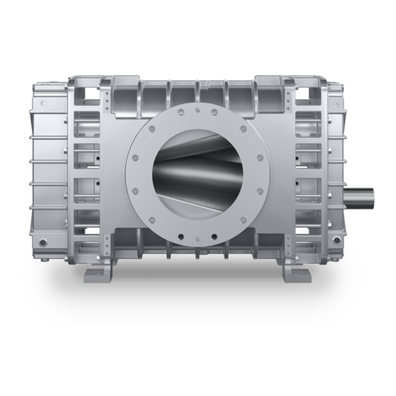
- Page 1 PD BLOWERS & VACUUM PUMPS HELIFLOW INDUSTRIAL SERIES 8” GEAR DIAMETER Owner’s Manual 8” HELIFLOW HF-7-604 Version 01 March 15, 2018 HF-7-604 Page 1...
-
Page 2: Maintain Blower Reliability And Performance
Rely upon the knowledge and experience of you AUTHORIZED DISTRIBUTOR and let them assist you in making the proper parts selection for your blower. For the location of your local authorized Gardner Denver blower distributor refer to the yellow pages of your phone directory, check the Web site at www.gardnerdenverproducts.com... -
Page 3: Foreword
FOREWORD Gardner Denver blowers are the result of advanced engineering and skilled manufacturing. To be assured of receiving maximum service from this machine, the owner must exercise care in its operation and maintenance. This book is written to give the operator and maintenance department essential information for day-to-day operation, maintenance and adjustment. -
Page 4: Safety Precautions
SAFETY PRECAUTIONS Safety is everybody’s business and is based on your use of good common sense. All situations or circumstances cannot always be predicted and covered by established rules. Therefore, use your past experience, watch out for safety hazards and be cautious. Some general safety precautions are given below: Failure to observe these notices could result in injury to or death of personnel. -
Page 5: Table Of Contents
SECTION 1, Equipment Check ........................9 SECTION 2, Installation ..........................11 SECTION 3, MAINTENANCE ........................20 GARDNER DENVER LUBRICANT ORDER INFORMATION ..............21 SECTION 4, OPERATION .......................... 24 SECTION 5, SPECIAL TOOL REQUIRED ....................27 SECTION 6, DISASSEMBLY INSTRUCTIONS ..................28 SECTION 7, ASSEMBLY INSTRUCTIONS .................... - Page 6 Index AIR FILTERS AND FILTER SILENCERS ..23 LUBRICATION SERVICE ........ 20 ASSEMBLY INSTRUCTIONS, SECTION 7 MAINTENANCE, SECTION 3 ......20 ASSEMBLY INSTRUCTIONS ...... 33 MATRIX/MENU ..........7 BLOWER STARTUP CHECKLIST ....25 OPERATION, SECTION 4 DISASSEMBLY INSTRUCTIONS, SECTION 6 OPERATION ..........
- Page 7 LIST OF ILLUSTRATION Figure 2- 1 – HF 825 VERTICAL BLOWER MOUNTING CONFIGURATIONS AND OUTLINE ....12 Figure 2- 2 – HF 825 HORIZONTAL BLOWER MOUNTING CONFIGURATIONS AND OUTLINE ..13 Figure 2- 3 – HF-817 VERTICAL BLOWER MOUNTING CONFIGURATIONSAND OUTLINE ....14 Figure 2- 4 –...
-
Page 8: Matrix/Menu
GARDNER DENVER HELIFLOW INDUSTRIAL MATRIX/MENU NOTICE TO CUSTOMER – To find the construction options for Your blower unit, FILL IN THE BALANCE OF LETTERS OR ___ ___ ___ ___ ___ ___ ___ NUMBERS FROM YOUR UNIT NAMEPLATE COLUMN NUMBER FOLLOW THE LINE DOWN AND OVER FROM EACH SPACE THUS FILLED IN TO FIND THE APPROPRIATE CONSTRUCTION OPTION WITH WHICH YOUR MACHINE IS EQUIPPED. -
Page 9: Introduction Your Key To Trouble Free Service
There is no guesswork in the manufacture of your highly advanced Gardner Denver blower and there must be none in preparing the blower to get the job done in the field. -
Page 10: Section 1, Equipment Check
STORAGE Your Gardner Denver Blower was packaged at the factory with adequate protection to permit normal storage for up to six (6) months. If the unit is to be stored under adverse conditions or for extended periods of time, the following additional measures should be taken to prevent damage. - Page 11 REMOVING PROTECTIVE MATERIALS The shaft extension is protected with rust inhibitor which can be removed with any standard solvent. Follow the safety directions of the solvent manufacturer. Blower inlet and outlet are temporarily capped to keep out dirt and other contaminants during shipment. These covers must be removed before start-up.
-
Page 12: Section 2, Installation
SECTION 2 INSTALLATION LIFTING The basic blower is supplied with lifting lugs at each top corner of the unit. Attach lifting equipment only to the lifting lugs. LOCATION Install the blower in well lit, clean and dry place with plenty of room for inspection and maintenance. FOUNDATION For permanent installations we recommend concrete foundations be provided, and the equipment should be grouted to the concrete. -
Page 13: Figure 2- 1 - Hf 825 Vertical Blower Mounting Configurations And Outline
302HYG800‐B (Ref. Drawing) Figure 2- 1 – HF 825 VERTICAL BLOWER MOUNTING CONFIGURATIONS AND OUTLINE... -
Page 14: Figure 2- 2 - Hf 825 Horizontal Blower Mounting Configurations And Outline
303HYG800‐B (Ref. Drawing) Figure 2- 2 – HF 825 HORIZONTAL BLOWER MOUNTING CONFIGURATIONS AND OUTLINE... -
Page 15: Figure 2- 3 - Hf-817 Vertical Blower Mounting Configurationsand Outline
304HYG800‐B (Ref. Drawing) Figure 2- 3 – HF 817 VERTICAL BLOWER MOUNTING CONFIGURATIONS AND OUTLINE... -
Page 16: Figure 2- 4 - Hf-817 Horizontal Blower Mounting Configurationsand Outline
305HYG800‐B (Ref. Drawing) Figure 2- 4 – HF 817 HORIZONTAL BLOWER MOUNTING CONFIGURATIONS AND OUTLINE... - Page 17 NOTICE When changing mounting configuration, it will be necessary to reposition oil level gauge (H), and drain plug (A). For Vertical Models, the oil slinger must be on the lower rotor or blower failure is immediate. The rotation direction must correspond to the direction of the arrows located on the machine body.
- Page 18 On the direct connected units, alignment and lubrication of couplings to specifications of the coupling manufacturer is very important. When mounted drives are supplied from the factory, proper alignment has been established before shipment. However, during shipping, handling and installation, it is likely that the alignment has been disturbed and final adjustment must be made before startup.
-
Page 19: Figure 2- 5 - Belt Drive Overhung Load Calculations
Maximum Gear Dimensions Allowable Diameter (Inches) Moment (Inches) (LB-IN) (Max) 8.44 3.86 0.50 19500 MAXIMUM ALLOWABLE MOMENT DRIVE SHAFT ILLUSTRATION 0.000 1.000 0.250 0.966 0.500 0.926 0.750 0.879 1.000 0.823 1.250 0.751 0.025 0.997 0.275 0.962 0.525 0.922 0.775 0.874 1.025 0.816 1.275... - Page 20 PIPING Inlet and discharge connections on all blowers are large enough to handle maximum volume with minimum friction loss. Reducing the pipe diameter on either inlet or discharge will only create additional line loss and increase the overall pressure differential. Excessive weight of piping and fittings will cause internal misalignment and premature wear.
-
Page 21: Section 3, Maintenance
7500 hours. Change the oil often enough that it appears clean and clear when drained from the sump. The oil drain plug is located at (A). Gardner Denver blowers are shipped dry from the factory. Do not attempt to operate the blower before following proper lubrication instructions. Permanent damage to the gears, bearings and seals will occur. -
Page 22: Gardner Denver Lubricant Order Information
1 Quart 28G46 Case/ 12 Quarts 28G47 1 Gallon 28G42 5 Gallon Pail 28G44 55 Gallon Drum 28G45 Call your local Gardner Denver distributor to place your order for Gardner Denver Lubricants. Your Authorized Gardner Denver Distributor is: HF-7-604 Page 21... -
Page 23: Figure 3-3 - Synthatic Lubrication Chart
AEON PD Series Lubricant is formulated especially for positive displacement blower service to provide maximum blower protection at any temperature. One fill of AEON PD Series Lubricant will last a minimum of 4 times longer than a premium mineral oil. Ambient Temperatures Less than 10 F to 32... - Page 24 AIR FILTERS AND FILTER SILENCERS Servicing the air filters is one of the most important maintenance operations to be performed to insure long blower life. Servicing frequency of filter elements is not time predictable. A differential pressure indicator, with a continuous gauge reading, should be installed across the inlet filter.
-
Page 25: Section 4, Operation
SECTION 4 OPERATION Future operating problems can be avoided if proper precautions are observed when the equipment is first put into service. NOTICE Machines are shipped without oil in the sumps. Do not operate before adding lubricant. Before starting under power, the blower should be turned over by hand to make certain there is no binding, or internal contact. - Page 26 “Jog” the unit with the motor a few times to check that rotation is in the proper direction, and to be certain it turns freely and smoothly. The internal surfaces of all Gardner Denver units are mist sprayed with a rust preventive to protect the machine during the shipping and installation period. This film should be removed upon initial startup.
- Page 27 SAFETY PRECAUTIONS 1. Do not operate blower with open inlet or outlet port. 2. Do not exceed specified vacuum or pressure limitations. 3. Do not operate above or below recommended blower speed range. 4. Blower is not to be used where non-sparking equipment is specified. 5.
-
Page 28: Section 5, Special Tool Required
* Tools T25 and T26 are supplied as part of “SKF Oil Injector Kit 729101”. This kit can be purchased from an authorized Gardner Denver or SKF distributor. + Enerpac hydraulic cylinder tool T28 is sold separately. It must be used with a hand pump or electric pump which can be purchased from an authorized Enerpac distributor. -
Page 29: Section 6, Disassembly Instructions
SECTION 6 DISASSEMBLY INSTRUCTIONS 1. Initial Blower Inspection, Oil Draining and Cover Removal NOTICE 1. Numbers in parenthesis ( ) refer to balloon numbers in figures and in assembly drawings. 2. Oil seal should be replaced during overhaul as a matter of service policy.. Exercise care not to damage the Sump cover oil seal bore when removing the oil seal. - Page 30 2. Oil Slinger/Spacer Removal and Gear Inspection Remove the locknut (23), oil slinger (43), and gear spacer (20) from the gear end rotor shaft using the nut driver tool (T12). Remove the locknut (23), and gear spacer (20) from the gear end second rotor shafts using the nut driver tool (T12).
- Page 31 3. Gear Removal Do not remove the locking nut (23), this will keep gear from shooting off of the rotor when pressurized. The pressure of the oil during disassembly may reach 2000 bar and the incorrect assembly of the injector or pump may cause serious physical damage due to the jets of oil under pressure.
- Page 32 4. Bearing Housing, Bearings and Oil Slinger Removal NOTICE Bearings and internal oil slinger should be replaced during overhaul as a matter of service policy. Exercise care not to damage the bearing bores on the bearing housing when removing bearings and oil seals.
- Page 33 5. Ring Carrier Removal Remove the piston rings from each ring carrier. Pull ring carriers from both rotor shafts using ring carrier puller (T13) and two bolts (29). Inspect all piston rings for signs of damage and abnormal wear. Rings with damage and abnormal wear should be replaced.
-
Page 34: Section 7, Assembly Instructions
SECTION 7 ASSEMBLY INSTRUCTIONS Torque Specifications Description Item number Torque FT-LBS Socket Head Cap Screw Hex Head Cap Screw Bearing Locknut Hex Head Cap Screw Hex Head Cap Screw Hex Head Cap Screw Socket Head Screw Key Symbols Used HF-7-604 Page 33... - Page 35 1. Bearing Housing Insert Installation NOTICE Numbers in parenthesis ( ) refer to balloon numbers in figures and in assembly drawings. Make sure Insert is fully seated. Use extreme care when installing. Cleaning and Inspection Before reassembling the blower and any parts that are to be reused should be inspected and cleaned thoroughly. Ensure all threads are clean, if needed run tap through threads.
- Page 36 2. Piston Ring Installation Lubricate o-ring (17) with o-ring grease (51) (Parker Super Lube Hi-Temp 884-2 or similar) and insert into the groove on the inner diameter of the ring carrier (7). Install four piston rings (8) into the piston ring carrier (7).
- Page 37 4. Rotors and Bearing Housing Assembly - Gear End Bearing housing must be oriented so that dowel holes in bearing housing lines up with dowels in air cylinder. 13. From the blower model designation, determine drive shaft (long rotor) location and the direction it rotates. 14. Insert rotors (2) into the cylinder individually using an overhead hoist. Verify that the long end of the drive rotor extends through the drive end bearing housing and that it is in the correct bore. Ensure that the rotation of each rotor matches the arrows on the outside of the air cylinder. Ensure that rotor lobes match the triangular shape of the discharge port. ...
- Page 38 5. Ring Carrier Installation - Gear and Drive Ends NOTICE Make sure Ring Carriers are fully seated. This is important in order to set up right fix end clearance. Use extreme care when installing ring carriers and piston rings in the bearing housing. Do not attempt to perform installation without the use of specified tools in step 21.
- Page 39 6. Slinger Installation - Gear End NOTICE Make sure oil slinger are fully seated. New oil slinger should be installed each time the bearing housing is removed. 25. Position the assembly vertically with the gear end on the top. 26. Apply a light coat of oil to the outside diameter of the previously installed ring carriers on drive rotor and to the Inside diameter of the oil slinger 9 27. Press oil slinger (9) using tools T1, T2, T3, T8, T16, and T22 until seated against shoulder of ring carrier. 28. Repeat steps 26 and 27 for the idler rotor on this end. ...
- Page 40 7. Setting Fix End Clearances - Gear End NOTICE Make sure Ring Carriers are fully seated. This is important in order to set up correct fix end clearance. Make sure the ring carrier on Idler rotor is properly seated against rotor face by Inserting tools (T22) on the ring carrier and pressing it slightly by hand.
- Page 41 8. (C2) Bearings Installation - Gear End NOTICE The maximum load applied to this all thread rod must never exceed 5 tons. Locate the 2 spherical roller bearings (11) that are to be installed on the gear end of both rotors. The gear end bearings and the drive end bearings are the same physical size and appear to be the same part.
- Page 42 9. Bearing Retainer Plates Installation Place two bearing retainer plates (13) on the gear end housing. Ensure the oil drain slots on the plates are positioned over drain holes in the bearing housing as to not block the drain holes. Mount bearing retainer plates onto the gear end bearing housing with seven screws (14) and lock washers (32).
- Page 43 10. Bearings and Oil Slingers Installation - Drive End NOTICE 1. Make sure oil slinger are fully seated. 2. New oil slinger should be installed each time the bearing housing is removed. 3. The maximum load applied to this all thread rod must never exceed 5 tons. Repeat steps 26, 27 and 28 to install oil slingers on the drive end.
- Page 44 11. Preparation for Gear Installation NOTICE It is extremely important to maintain gap dimension (distance between gear back face and spacer) in range 0.175”-0.200” or timing will be lost. Inlet Inlet Drive Drive Rotor Rotor Carefully clean tapered ends of the shafts and tapering bores of the gears. Every gear and rotor will be stamped with L or R to match each gear with its paired rotor.
- Page 45 12. Gear Installation Fixed gear should be on left rotor looking from discharge port. Always install fix gear first. Place fixed gear (18), with screw holes facing up, on its matching rotor shaft. Place gear tool (T21) over rotor shaft and onto gear. Screw the hydraulic bolt (T4), with nut (T5) and flat washer (T6), through gear tool (T21) and into the rotor shaft.
- Page 46 13. Slinger and Nut Installation - Vertical Configuration NOTICE The oil slingers must be installed on the bottom shaft. Assure the slingers are installed on the drive and gear ends. The drive end slinger is smaller in diameter than the gear end slinger. Position the assembly vertically with the gear end on the top.
- Page 47 14. Slinger and Nut Installation - Horizontal Configuration NOTICE The oil slingers must be installed on the bottom shaft. Assure the slingers are installed on the drive and gear ends. The drive end slinger is smaller in diameter than the gear end slinger. Position the assembly vertically with the drive end on the top.
- Page 48 15. Sump Cover Installation Position the assembly vertically with the drive end on the top. Using a pump type oil can apply oil (AEON PD) to all of the bearings. Turn the rotors to distribute the oil throughout the bearings. This will ensure that the bearings are lubricated when the blower is first started. Lubricate o-ring (33) with o-ring grease (Parker Super Lube Hi-Temp 884-2 or similar) and install the o-ring in the sump covers (4 gear end and 5 drive end).
- Page 49 16. Drive Seal Installation NOTICE Use extreme care when installing oil seals to prevent cutting the seal lip. Position the assembly vertically with the drive end on the top. Determine the proper orientation of the cover seal (26). The seal has two lips. The outer lip is shorter and when installed should point to- ward the keyway end of the drive rotor shaft.
- Page 50 17. Plugs and Mounting Feet Installation Install 1/8”plugs (16) in the four instrument holes in the air cylinder near the inlet and discharge ports. Determine the appropriate hole in each sump cover for the oil level gauge (35). The oil level will be in the lower part of the oil sump.
-
Page 51: Section 8, Parts List
SECTION 8 PARTS LIST 18. Parts List – Models HYGL_AA and HYGM_AA HF-7-604 Page 50... - Page 52 Parts List – Models HYGL_AA Ref. No. Description Quantity Part Number CYLINDER, MACH, HF825 301HYG002 ROTOR, LONG HF825 RIGHT HAND HELIX 308HYG010 ROTOR, SHORT HF825 LEFT HAND HELIX 309HYG010 BRG HOUSING, MACH, 8" HELIFLOW 300HYG006 COVER, GEAR END, 8" HELIFLOW 300HYG602 COVER, DRIVE END, 8"...
- Page 53 Parts List – Models HYGL_AA Ref. No. Description Quantity Part Number SPACER, GEAR END, 8" HELIFLOW 301HYG144 SLINGER, GEAR END, 8" HELIFLOW 302HYG173 LOCTITE 246, 250 ML BOTTLE 0.016 25BC884 LOCTITE 620, 250 ML BOTTLE 25BC749 FOOT, HORZ RIGHT, 8" HELIFLOW 306HYG166 FOOT, HORZ LEFT, 8"...
- Page 54 Parts List – Models HYGM_AA Ref. No. Description Quantity Part Number CYLINDER, MACH, HF817 305HYG002 ROTOR, LONG HF817 RIGHT HAND HELIX 304HYG010 ROTOR, SHORT HF17 LEFT HAND HELIX 305HYG010 BRG HOUSING, MACH, 8" HELIFLOW 300HYG006 COVER, GEAR END, 8" HELIFLOW 300HYG602 COVER, DRIVE END, 8"...
- Page 55 Parts List – Models HYGM_AA Ref. No. Description Quantity Part Number SPACER, GEAR END, 8" HELIFLOW 301HYG144 SLINGER, GEAR END, 8" HELIFLOW 302HYG173 LOCTITE 246, 250 ML BOTTLE 0.016 25BC884 LOCTITE 620, 250 ML BOTTLE 25BC749 FOOT, HORZ RIGHT, 8" HELIFLOW 306HYG166 FOOT, HORZ LEFT, 8"...
- Page 56 Overhaul Kit – 302HYG6010 Ref. No. Description Quantity Part Number RING-PISTON 300HYG163 SLINGER, INTERNAL SEAL - 8" HELIFLOW 300HYG173 SHIM SET 300HYG732 BEARING, SPH ROLLER TEN001039 BEARING, SPH ROLLER TEN001038 SCREW 1/2-13UNC x 1.00 LG NYLON INSERT 655EE04N WASHER-LOCK 1/2 HELICAL SPRING 95B5 LOCKNUT, BEARING 50Z17...
-
Page 57: Warranty
GENERAL PROVISIONS AND LIMITATIONS Gardner Denver, Inc. (the “Company”) warrants to each original retail purchaser (“Purchaser”) of its products from the Company or its authorized distributor that such products are, at the time of delivery to the Purchaser, made with good material and workmanship. No warranty is made with respect to: 1. - Page 58 NOTES:...
- Page 59 NOTES:...
- Page 60 NOTES:...
- Page 61 NOTES:...
- Page 62 NOTES:...
- Page 63 NOTES:...
Need help?
Do you have a question about the HELIFLOW 8 Series and is the answer not in the manual?
Questions and answers