Table of Contents
Advertisement
Original Instruction Manual
CL3-CAM Professional 5 Speed Lathe
CL4-CAM Professional Electronic Variable Speed Lathe
Including optional CL3/B Bowl Turning Attachment for CL Series Lathes
& RPLB24-48 Adjustable Lathe Stand for CL Series Lathes
Version 2.0
October 2012
It is important to register your product as soon as possible in order to receive efficient after sales
support and be entitled to the full 5 year guarantee. Your statutory rights are not affected.
Kg
Always wear safety glasses when
using woodworking equipment.
To register this product please visit
www.recordpower.info
Please see back cover for contact details.
Important
i
For your safety read instructions carefully before
assembling or using this product.
Always read the instructions
provided before using
Save this manual for future reference.
woodworking equipment.
1
Advertisement
Chapters
Table of Contents

Related Manuals for Record Power CL3-CAM


Summary of Contents for Record Power CL3-CAM
- Page 1 Original Instruction Manual CL3-CAM Professional 5 Speed Lathe CL4-CAM Professional Electronic Variable Speed Lathe Including optional CL3/B Bowl Turning Attachment for CL Series Lathes & RPLB24-48 Adjustable Lathe Stand for CL Series Lathes Version 2.0 October 2012 To register this product please visit www.recordpower.info...
-
Page 2: Table Of Contents
Explanation of Symbols General Health & Safety Guidance Additional Health & Safety Guidance for Woodturning Lathes Record Power Guarantee CL3-CAM & CL4-CAM Specifications Assembly Instructions Lubricating the Bronze Bearing Before Use Intended Use of the Lathe & Basic Woodturning Instructions Control Identification &... - Page 3 Dear Customer, Thank you for investing in a Record Power woodturning lathe, which has been designed to give you years of satisfying service. A complete list of accessories to enhance your enjoyment of woodturning is included at the back of this manual. Please do not forget to register your product with the authorised distributor in your country, details of whom can be found on the outside back cover of this manual.
-
Page 4: Explanation Of Symbols
1. Explanation of Symbols The symbols and their meanings shown below may be used throughout this manual. Please ensure that you take the appropriate action wherever the warnings are used. Mandatory Instructions Read and fully understand the instruction manual before attempting to use the machine. -
Page 5: General Health & Safety Guidance
2. General Health & Safety Guidance Ensure that you carefully read and fully understand the • If the machine is suitable to be used on a workbench, ensure that the instructions in this manual before assembly, installation and workbench is well constructed and capable of withstanding the weight use of this product. - Page 6 2. General Health & Safety Guidance - cont. 13. Store machines safely when not in use • Do not attempt to machine more than one work piece at a time. • When not in use, machines should be stored in a dry place, out of reach •...
-
Page 7: Additional Health & Safety Guidance For Woodturning Lathes
2. General Health & Safety Guidance - cont. 29. Disconnect the machine from the power supply 31. Warning! • When not in use, before servicing, changing blades etc. always • The use of any accessory or attachment, other than those recommended disconnect the machine from the power supply. -
Page 8: Record Power Guarantee
Guarantee should be made directly to Record Power or its Authorised Distributor Record Power guarantees that for a period of 5 years from the date (for details of the Authorised Distributor in your country please see of purchase the components of qualifying Products (see clauses 1.2.1 your Product manual or check www.recordpower.info for details). -
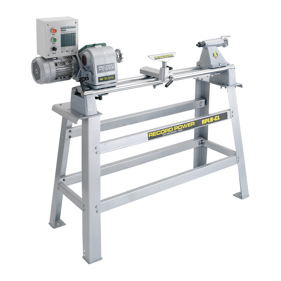
Page 9: Cl3-Cam & Cl4-Cam Specifications
The principle of kinematics is that three points of theory to the CL3-CAM and CL4-CAM lathes, wherever there is a critical piece of the contact provide the most stability. The best example of this is to compare the stability structure being assembled kinematics are employed giving unsurpassed stability and of a three legged stool and four legged stool. -
Page 10: Assembly Instructions
ASSEMBLy – IDENTIFyING CONTENTS Inside the shipping container you will find the following: 1a. CL3-CAM Headstock with motor & thread protector 1b. CL4-CAM Headstock & VSLK unit 2. 3 x Square straps 3. Cam lock banjo, washer and nyloc nut 4. -
Page 11: Initial Assembly
6. Assembly Instructions - cont. Before assembling and using your lathe, you must have a sturdy bench or stand for it. We recommend the Record Power RPLB24-48 Lathe Bench. If you wish to build your own bench, remember that the lathe is heavy. The bench must not move during use. - Page 12 6. Assembly Instructions & - cont. Angle Straps & Bed Bars Fig.6.2 Angle Strap Fig.6.3 2 pads 2. Introduce the angle straps to each of the end brackets positioned at either end of the assembly area. The angle straps should initially be placed at 90º...
- Page 13 6. Assembly Instructions - cont. Attaching the tailstock Fig.6.8a 1. Place the tailstock onto the bed bars at the right hand end of the assembly, again noting that the single point raised area for the kinematic design is at the front of the lathe, Figs.6.8a &...
- Page 14 6. Assembly Instructions - cont. Banjo & Toolrest Assembly Fig.6.13 Fig.6.15 1. Place the flat side of the banjo onto the bed bars Fig.6.13. 2. Introduce the square strap underneath the bed bars and feed the banjo screw through the hole in the square strap Fig.6.14.
- Page 15 6. Assembly Instructions - cont. CL3-CAM Headstock Assembly Fig.6.16 Fig.6.17 Please note: It is much easier to assemble the headstock with the CL3-CAM motor removed. See below for instructions on how to remove the motor. 1. Disconnect lathe from power source. Tension lever 2.
-
Page 16: Saddle
Fig.6.28. Finally replace the headstock cover plate and secure this with the Allen bolt. The assembly of the CL3-CAM lathe is now complete, Fig. 6.46. 2 pads The pulleys lock onto the shafts using two grub screws. - Page 17 6. Assembly Instructions - cont. CL4-CAM Headstock Assembly Fig.6.31 Fig.6.29 Please note: The CL4-CAM is packaged with the motor plate attached. This will need to be removed and fitted to the VSLK unit. 1. Remove headstock cover, Fig.6.29 and slacken Belt tension lever nut Belt tension lever the belt tensioner Fig.6.30.
- Page 18 Roll Pin Please note: The CL4-CAM head stock Motor shaft must now be attached to the bed bars. Tension lever Follow steps 16-21 of the CL3-CAM Head Pivot pin thread showing Stock Assembly instructions before through inside proceeding to step 2 below.
- Page 19 6. Assembly Instructions - cont. Pulley Alignment Fig.6.43 Fig.6.41 Correct pulley alignment is necessary in order to A Knurled Base Grub Screw minimise vibration. To check correct alignment which locates into the dog please follow the instructions below: grub screw. 1.
- Page 20 6. Assembly Instructions - cont. Fig.6.46 Fig.6.47...
-
Page 21: Lubricating The Bronze Bearing Before Use
Running The Lathe In 2. To assure longer bearing life, before first use the lathe must be “Run- In” for three hours on the middle step of the pulley (CL3-CAM) and speed setting 4 on the CL4-CAM. WARNING: Unattended machines can be dangerous. Be sure people and pets will not be exposed to the running lathe during this period. -
Page 22: Intended Use Of The Lathe & Basic Woodturning Instructions
8. Intended Use of the Lathe & Basic Woodturning Instructions Intended Use of the Lathe Fig.8.1 This lathe is designed for turning wood between centres or on the headstock (using appropriate accessories), for sanding and applying finishes to wood. It is not to be used for any other purpose. Doing so will invalidate the warranty and may cause serious harm to the user. - Page 23 There are a wide variety of specialised chisels and many complementary accessories available for Record Power lathes which enable a huge variety of work to be created. For further instructions on more advanced safe and effective woodturning, please seek professional training.
-
Page 24: Control Identification & Functions
3161 4648 WARNING: Do not use this equipment before reading the instruction manual. For genuine Record Power spares and accessories please telephone 01246 561 520 or email sales@recordpower.co.uk. Record Power Ltd, Unit B, Adelphi Way, Staveley S43 3LS www.recordpower.co.uk Always wear safety... -
Page 25: Lathe Operation
By changing the belt on to each of the five different pulleys the speed can the power source is restored. be varied from 425 to 2000 rpm on the CL3-CAM and 13 to 4648 rpm on the CL4-CAM. If the machine stalls due to overloading (following a dig-in whilst turning), switch the machine OFF by pressing the red button marked ‘O’. - Page 26 10. Lathe Operation - cont. SPEED SELECTION The speeds shown below represent the CL3-CAM speeds and also the approximate CL4-CAM speeds when the speed dial is set to half speed and the belt is positioned on the pulleys as shown.
- Page 27 1453 2150 3161 4648 Control WARNING: Do not use this equipment before reading the instruction manual. For genuine Record Power spares and accessories please telephone 01246 561 520 or email sales@recordpower.co.uk. Record Power Ltd, Unit B, Adelphi Way, Staveley S43 3LS www.recordpower.co.uk Always wear safety Always read glasses when using the instructions...
- Page 28 10. Lathe Operation - cont. CONTROLS AND FUNCTIONS OF THE CL3-CAM SWITCH BOX The CL3-CAM switch box is located on the Fig.10.2 motor unit, attached to the head stock. To turn the CL3-CAM on, press the green switch marked '|'. To stop the lathe, press the red switch marked ' '.
-
Page 29: Adjusting The Bronze Taper Bearing
Fig.10.14 BEARING The Tapered Bronze Bearing System fitted to Brass rod CL3-CAM and CL4-CAM is one of the finest bearing systems available and a long established and well proven engineering solution. Take time to learn the correct maintenance and adjustment... -
Page 30: Maintenance
11. Maintenance Outer Inner Fig. 11.0 locking locking Cross Section of Spindle & Oil cap ring Bottom ring Bearing Assembly grub grub Large screw screw washer Spindle Allen Thread bolt protector Bronze bearing Back Wrench flat (to aid removal bearing of accessories from spindle nose) CAUTION! - Page 31 11. Maintenance - cont. along the full length of the spindle inside the Fig.11.8 Fig.11.12 headstock. Fig. 11.7. Inner locking ring Back bearing 7. Unscrew the inner locking ring from the bronze bearing inside the headstock. To loosen this ring place the brass rod into one of the notches around the locking ring and tap with a mallet Fig.
- Page 32 11. Maintenance - cont. 14. The new spindle & bearing can now be Fig.11.16 Fig.11.20 Back fitted, ensure that the outer locking ring (still bearing fitted to the old bearing) is transferred to the new bearing. Fig. 11.15. 15. Screw the thread protector back on to the spindle.
- Page 33 11. Maintenance - cont. the back of the headstock. Do not over tighten Fig.11.25 Fig.11.27 this, the bolt should only be turned until finger tight Fig. 11.23, then apply a 1/4 of a turn with an Allen key Fig. 11.24. 22.
-
Page 34: Troubleshooting
12. Troubleshooting Symptom Possible Cause Possible Remedy Motor will not start. Not connected to power supply. Check connection to power supply and re-try. Faulty fuse or circuit breaker tripped. Check fuse and replace if necessary. Check circuit breaker and re-set if necessary Check that the work piece can rotate freely. -
Page 35: Spare Parts Identification
13. Spare Part Identification VSLK for CL4-CAM only... - Page 36 13. Spare Part Identification - cont. ITEM PART DESCRIPTION BOHZ Headstock ZJB-CAM Tailstock End bracket BOBJ-CAM Banjo CLO/J 10” Tool rest End bracket clamp Tool rest base clamp BOLZ Headstock cover Tailstock Handwheel Headstock base Spindle pulley - 5 Speed Motor pulley –...
-
Page 37: Electrical Connection & Wiring Diagrams
In the case of the BS1363 plug for use in the UK, always ensure that it is fitted with a fuse conforming to BS1362 appropriate to the rating of the CL3-CAM Wiring Diagram CL4-CAM Wiring Diagram ... -
Page 38: Contents Of The Cl3/B Package
15. Contents of the CL3/B Package Bracket Swivel bracket Tubular bowl rest Banjo Banjo clamping screw Swivel bracket clamping screw Bracket securing screw Swivel bracket secondary screw Ratchet handle for tool rest (banjo) 10 Allen key 16. Assembly of the CL3/B Please note: The bracket supplied as part of the CL3/B replaces Fig.16.1 the end bracket supplied with the lathe, at the head stock end. -
Page 39: Use & Application Of The Cl3/B
17. Use & Application of the CL3/B Normal Duty work .17.1 For normal duty work the swivel bracket clamping screw is sufficient to secure the swivel bracket in position but if movement is anticipated then the swivel bracket secondary screw should also be tightened, Fig 17.1. Thin work .17.2 For thin work the headstock can be swivelled to give maximum clearance for... -
Page 40: Cl3/B Parts List & Diagrams
18. CL3/B Parts List & Diagrams Part Number Description Quantity Part Number Description Quantity Bracket Tube For Tubular Bowl Rest BOST Swivel Bracket ZABM Nut - M12 BOEB Clamping Screw For Banjo ZABO Washer - M12 BOES Clamping Screw For Swivel Bracket ZAES Washer - Large CLK1... -
Page 41: Contents Of The Rplb24-48 Package
19. Contents of the RPLB24-48 Package Remove bench parts from packaging and lay out in a clean, uncluttered area. Check contents against parts list and diagram, Fig 19.1, then follow assembly instructions. Fig.19.1 Ref No Part No Description Quantity Ref No Part No Description Quantity... -
Page 42: Rplb24-48 Specifications
20. RPLB24-48 Specifications The RPLB 24-48 Lathe bench can be adjusted to suit the CL3-CAM and CL4-CAM Record Power lathes. It is also possible to fit the DML36SH-CAM Record Power lathe, providing alternative holes are drilled. Other lathes may be accommodated by drilling extra holes in the side rails or by mounting a wooden top with suitable holes for bolting the lathe down. - Page 43 9. Finally, fully tighten all nuts and bolts. 10. If the bench needs to be lengthened or shortened to suit a different Record Power lathe, this can be done by unscrewing the 8 M10 bolts (14), extending or retracting the bench, re-aligning the bolts (14) with the...
-
Page 44: Fitting A Lathe To The Rplb
3. For the CL3-CAM and CL4-CAM lathes use the Fig.22.2 holes in the top plates to bolt the lathe to the bench as indicated, Fig 22.1. -
Page 45: Eu Declaration Of Conformity
EU Declaration of Conformity Cert No: EU / CL3 / 1 RECORD POWER LIMITED, Unit B, Adelphi Way, Ireland Industrial Estate, Staveley, Chesterfield, Derbyshire S43 3LS declares that the machinery described:- 1. Type: Professional Woodturning Lathe 2. Model No: CL3-CAM & CL4-CAM 3. - Page 48 Woodworking Machinery & Accessories United Kingdom Eire Australia New Zealand Record Power Ltd Record Power Ltd Tools 4 Industry Tools 4 Industry Unit B Adelphi Way, Ireland Unit B Adelphi Way, Ireland Po Box 3844 Po Box 276079 Industrial Estate, Staveley,...
Need help?
Do you have a question about the CL3-CAM and is the answer not in the manual?
Questions and answers
Hi Can the headstock be turned to be able to turn larger bowl diameters, not seeing in sintruction manual? Record Cl3
Yes, the headstock of the Record Power CL3-CAM can be rotated 90º to accommodate larger bowl diameters, up to a maximum of 30 inches, when used with the optional bowl rest (part no. CL3B).
This answer is automatically generated