Table of Contents
Advertisement
Original Instruction Manual
DML36SH-CAM Swivel Head 4 Speed Intermediate Lathe
Version 2.0
October 2012
It is important to register your product as soon as possible in order to receive efficient after sales
support and be entitled to the full 5 year guarantee. Your statutory rights are not affected.
Kg
Always wear safety glasses when
using woodworking equipment.
To register this product please visit
www.recordpower.info
Please see back cover for contact details.
Important
i
For your safety read instructions carefully before
assembling or using this product.
Always read the instructions
provided before using
Save this manual for future reference.
woodworking equipment.
1
Advertisement
Table of Contents

Related Manuals for Record Power DML36SH-CAM


Summary of Contents for Record Power DML36SH-CAM
- Page 1 Original Instruction Manual DML36SH-CAM Swivel Head 4 Speed Intermediate Lathe Version 2.0 October 2012 To register this product please visit www.recordpower.info It is important to register your product as soon as possible in order to receive efficient after sales support and be entitled to the full 5 year guarantee. Your statutory rights are not affected.
-
Page 2: Table Of Contents
Contents Explanation of Symbols General Health & Safety Guidance Additional Health & Safety Guidance for Woodturning Lathes Record Power Guarantee Specifications Assembly Instructions Intended Use of the Lathe & Basic Woodturning Instructions Control Identification & Functions Lathe Operation 10 Maintenance 11 Troubleshooting 12 Spare Parts Identification... - Page 3 Dear Customer, Thank you for investing in a Record Power woodturning lathe, which has been designed to give you years of satisfying service. A complete list of accessories to enhance your enjoyment of woodturning is included at the back of this manual. Please do not forget to register your product with the authorised distributor in your country, details of whom can be found on the outside back cover of this manual.
-
Page 4: Explanation Of Symbols
1. Explanation of Symbols The symbols and their meanings shown below may be used throughout this manual. Please ensure that you take the appropriate action wherever the warnings are used. Mandatory Instructions Read and fully understand the instruction manual before attempting to use the machine. -
Page 5: General Health & Safety Guidance
2. General Health & Safety Guidance Ensure that you carefully read and fully understand the • If the machine is suitable to be used on a workbench, ensure that the instructions in this manual before assembly, installation and workbench is well constructed and capable of withstanding the weight use of this product. - Page 6 2. General Health & Safety Guidance - cont. 13. Store machines safely when not in use • Do not attempt to machine more than one work piece at a time. • When not in use, machines should be stored in a dry place, out of reach •...
-
Page 7: Additional Health & Safety Guidance For Woodturning Lathes
2. General Health & Safety Guidance - cont. 29. Disconnect the machine from the power supply 31. Warning! • When not in use, before servicing, changing blades etc. always • The use of any accessory or attachment, other than those recommended disconnect the machine from the power supply. -
Page 8: Record Power Guarantee
Guarantee should be made directly to Record Power or its Authorised Distributor Record Power guarantees that for a period of 5 years from the date (for details of the Authorised Distributor in your country please see of purchase the components of qualifying Products (see clauses 1.2.1 your Product manual or check www.recordpower.info for details). -
Page 9: Specifications
KINEMATIC DESIGN Throughout this manual you will find references to kinematics and the the stool to become unstable and move. Record Power apply the kinematic design kinematic design of this product. The principle of kinematics is that three points of theory to the CL3-CAM and CL4-CAM lathes, wherever there is a critical piece of the contact provide the most stability. -
Page 10: Assembly Instructions
6. Assembly Instructions Assembly – identifying contents Inside the shipping container you will find the following: Headstock & saddle Tailstock 3 X square straps Banjo 2 x end brackets 2 x wooden bench mounting washers (not required on DML24S Legstand, for use when mounting to a wooden bench) Toolrest 2 x angle straps... - Page 11 6. Assembly Instructions - cont. Before assembling and using your lathe, you must have a sturdy bench or stand for it. We recommend the Record Power DML24S Legstand. If you wish to build your own bench, remember that the lathe is heavy. The bench must not move during use.
- Page 12 6. Assembly Instructions & - cont. 7. Return the assembled legstand to its upright Fig.6.3 Fig.6.4B position. It maybe useful at this point to make sure that the legs are all aligned correctly and adjust if necessary. The bottoms of the legs are angled slightly to provide a solid base.
- Page 13 6. Assembly Instructions - cont. Assembly of the Bed when Fig.6.6B Mounting to a Bench 1. Position the end brackets roughly in position at both ends of the bench. Please note: If the optional DML-BR bowl bracket is to be fitted use this in the assembly procedure at this point in place of the headstock end bracket, Fig 6.7A.
- Page 14 6. Assembly Instructions - cont. Fig.6.8 Attaching the Tailstock 1. Place the tailstock onto the bed bars at the right hand end of the assembly, again noting that the raised area for the kinematic design is Recess at the front of the lathe, Figs.6.8A & 6.8B. 2.
- Page 15 6. Assembly Instructions - cont. Banjo & Toolrest Assembly Fig.6.12 Fig.6.14 1. Place the flat side of the banjo onto the bed bars and insert the toolrest into the banjo Fig.6.12. 2. Introduce the square strap underneath the bed bars and feed the banjo screw through the hole in the square strap Fig.6.12.
- Page 16 6. Assembly Instructions - cont. Headstock Assembly Fig.6.16 Fig.6.21 1. Place the saddle on the bed bars, Fig.6.16. 1. Remove the cover plate from the headstock using the Allen key, Fig.6.17. 2. When fitting the remaining locking handle and square strap ensure that recess part of the square strap is on the same side as the white indication line on the saddle, Fig.6.18.
- Page 17 6. Assembly Instructions - cont. Fig.6.23...
-
Page 18: Intended Use Of The Lathe & Basic Woodturning Instructions
7. Intended Use of the Lathe & Basic Woodturning Instructions Intended Use of the Lathe Fig.8.1 This lathe is designed for turning wood between centres or on the headstock (using appropriate accessories), for sanding and applying finishes to wood. It is not to be used for any other purpose. Doing so will invalidate the warranty and may cause serious harm to the user. - Page 19 There are a wide variety of specialised chisels and many complementary accessories available for Record Power lathes which enable a huge variety of work to be created. For further instructions on more advanced safe and effective woodturning, please seek professional training.
-
Page 20: Control Identification & Functions
8. Control Identification & Function Fig.8.1 TAILSTOCK CAM LOCK TOOLREST CAM LOCK Control Function Operation / Comment Tool rest Supports turning tool. Position as per lathe safety instructions. 2 prong centre Holds and drives workpiece for spindle turning. Provides driving force from motor. Firm contact is required. Cup centre Supports free end for spindle turning. -
Page 21: Lathe Operation
AFTER A POWER FAILURE OR OVERLOAD from 450 to 2000 rpm. The DML36SH-CAM lathe is fitted with a no volt release (NVR) switch which will cut out in the event of a power failure preventing automatic re-starting when the power source is restored. - Page 22 9. Lathe Operation - cont. CONTROLS AND FUNCTIONS OF THE DML36SH-CAM SWITCH BOX The DML36SH-CAM switch box is located on the Fig.9.1A motor unit, attached to the head stock. To turn the DML36SH-CAM on, press the green switch marked '|'. To stop the lathe, press the red switch marked ' '.
-
Page 23: Maintenance
10. Maintenance Fig. 10.0 Cross Section of Spindle & Bearing Assembly Bottom Grub Large Grub Screw Washer Screw Spindle Allen Thread Bolt protector Back Wrench flat (to aid removal of bearing accessories from spindle nose) CAUTION! Fig.10.4 Fig.10.1A Fig.10.1B End of spindle Before carrying out any adjustments or Back maintenance ensure that the machine... - Page 24 10. Maintenance - cont. 6. Taking a suitable drift such as a brass rod or Fig.10.6A Fig.10.10A piece of timber and a mallet drive the spindle from the back bearing through the headstock, Fig.10.6A. If you are not replacing the bearings take care not to damage the bearing itself, ensure you only strike the spindle.
- Page 25 10. Maintenance - cont. 14. Slide the spindle back into the headstock Fig.10.12 and into the pulley. Ensure that the drive belt is fitted around the spindle pulley, Fig.10.11. 15. While the spindle and bearing is being knocked into place, one hand must be used to keep rotating the spindle a 1/4 turn at every strike of the mallet, Fig.10.12.
-
Page 26: Troubleshooting
11. Troubleshooting Symptom Possible Cause Possible Remedy Motor will not start. Not connected to power supply. Check connection to power supply and re-try. Faulty fuse or circuit breaker tripped. Check fuse and replace if necessary. Check circuit breaker and re-set if necessary Check that the work piece can rotate freely. -
Page 27: Spare Parts Identification
12. Spare Part Identification... - Page 28 12. Spare Part Identification - cont. ITEM PART DESCRIPTION End bracket Angle strap ZAES Washer – M12 large CKSM Spindle pulley – 4 speed CKMM Motor pulley – 4 speed Main spindle Thread protector Toolrest stem 90º Back centre Tailstock barrel BOPM Motor Plate, Switch, Cable &...
-
Page 29: Electrical Connection & Wiring Diagram
In the case of the BS1363 plug for use in the UK, always ensure that it is fitted with a fuse conforming to BS1362 appropriate to the rating of the DML36SH-CAM Wiring Diagram ... -
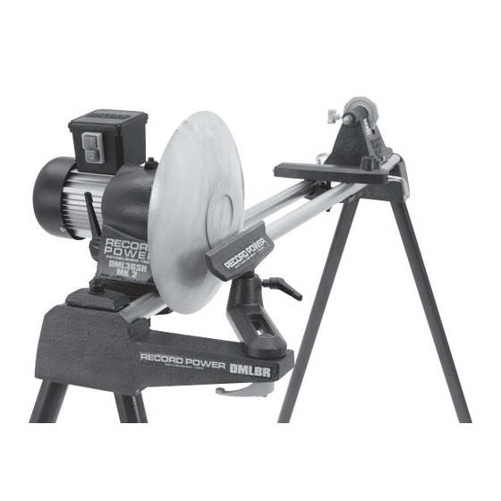
Page 30: Dml-Br Bowl Turning Attachment Assembly
14. DML-BR Bowl Turning Attachment Assembly Fig.15.1 M12 x 50mm Bolt Part No. (AUXB) Warning: Ensure that the power supply to the lathe is turned off and disconnected before starting the conversion of your Bowl Rest existing lathe. Banjo Part No. (CKBJ) 1. -
Page 31: Eu Declaration Of Conformity
EU Declaration of Conformity Cert No: EU / DML36SH-CAM / 1 RECORD POWER LIMITED, Unit B, Adelphi Way, Ireland Industrial Estate, Staveley, Chesterfield, Derbyshire S43 3LS declares that the machinery described:- 1. Type: Professional Woodturning Lathe 2. Model No: DML36SH-CAM 3. - Page 32 Woodworking Machinery & Accessories United Kingdom Eire Australia New Zealand Record Power Ltd Record Power Ltd Tools 4 Industry Tools 4 Industry Unit B Adelphi Way, Ireland Unit B Adelphi Way, Ireland Po Box 3844 Po Box 276079 Industrial Estate, Staveley,...
Need help?
Do you have a question about the DML36SH-CAM and is the answer not in the manual?
Questions and answers