Table of Contents
Advertisement
Quick Links
Original Instruction Manual
MAXI-1 Heavy
Cast Iron Swivel
Head Variable
Speed Lathe
Version 3.2
January 2015
It is important to register your product as soon as possible in order to receive efficient after sales
support and be entitled to the full 5 year guarantee. Your statutory rights are not affected.
Kg
Always wear safety glasses when
using woodworking equipment.
To register this product please visit
www.recordpower.info
Please see back cover for contact details.
Important
i
For your safety read instructions carefully before
assembling or using this product.
Always read the instructions
provided before using
Save this manual for future reference.
woodworking equipment.
Advertisement
Table of Contents

Related Manuals for Record Power MAXI-1


Summary of Contents for Record Power MAXI-1
- Page 1 Original Instruction Manual MAXI-1 Heavy Cast Iron Swivel Head Variable Speed Lathe Version 3.2 January 2015 To register this product please visit www.recordpower.info It is important to register your product as soon as possible in order to receive efficient after sales support and be entitled to the full 5 year guarantee.
-
Page 2: Table Of Contents
Contents 1. Health & Safety & Guarantee Information Explanation of Symbols General Health & Safety Guidance Additional Health & Safety for Woodturning Lathes Record Power Guarantee 2. Machine Description Machine identification Getting to know your machine Technical specification 3. Assembly... -
Page 3: Explanation Of Symbols
1.1 Explanation of Symbols The symbols and their meanings shown below may be used throughout this manual. Please ensure that you take the appropriate action wherever the warnings are used. Mandatory Instructions Read and fully understand the instruction manual before attempting to use the machine. -
Page 4: General Health & Safety Guidance
1.2 General Health & Safety Guidance Ensure that you carefully read and fully understand the 6. The machine should be level and stable at all times instructions in this manual before assembly, installation and use • When using a leg stand or cabinet base that is designed to be fitted to the of this product. - Page 5 1.2 General Health & Safety Guidance complete stop. enough to tip when not held down to the table top. • If the work area is to be left unattended, all machinery should be switched • Do not use another person as a substitute for a table extension, or as ‘OFF’...
-
Page 6: Additional Health & Safety For Woodturning Lathes
1.2 General Health & Safety Guidance determine that it will operate properly and perform its a risk of personal injury or damage to the machine and invalidation of the intended function. warranty. • Check for alignment of moving parts, binding of moving parts, breakage 32. -
Page 7: Record Power Guarantee
Guarantee should be made directly to Record Power or its Authorised Distributor Record Power guarantees that for a period of 5 years from the date (for details of the Authorised Distributor in your country please see of purchase the components of qualifying Products (see clauses 1.2.1 your Product manual or check www.recordpower.info for details). -
Page 8: Machine Description
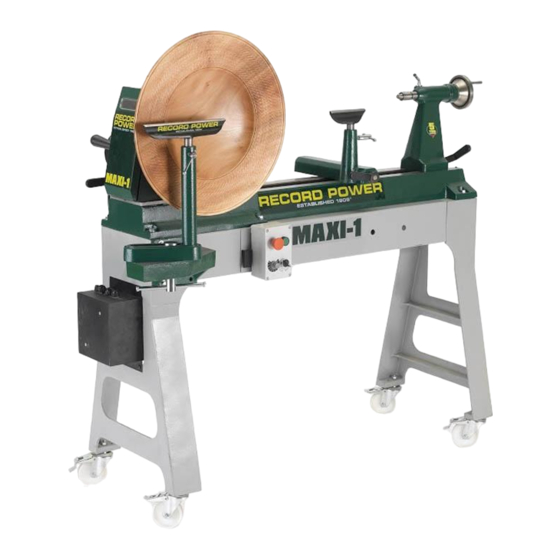
2. Machine Description 2.1 Machine identification There is an identification label fixed to the machine, containing the manufacturer's details, year of construction, serial number and specifications. 2.2 Getting to Know Your Machine Stand Leg Tool rest Stand Body Spur centre Lathe Bed M. -
Page 9: Assembly
3. Assembly A 1 x lathe bed including motor, transducer and control switch. B 2 x stand body C 2 x stand leg D Wrench E Knockout bar F 12” tool rest G 6” tool rest H Loose parts bag Instruction manual... -
Page 10: Lifting
3. Assembly Sling 2000 kgs Fig.3.1 MAXI-1 Packing Box Caution: Many of the items are very heavy. We recommend that assistance is sought before trying to lift the larger components. Note: The machine must not be plugged in and the power switch must be in the OFF position until assembly is complete. - Page 11 3. Assembly 3.6 Mounting the Switch box to the Stand Fig.3.6 Insertion Pegs 1. Place the switch box insertion pegs (Fig.3.6) into the mounting holes on the main body of the stand (Fig.3.7). 2. Ensuring that the power cable is free to hang down from the switch box, push the two locking catches down to secure the switch box in place (Fig.3.8).
-
Page 12: Adjustment
4. Adjustment Fig.4.1 4.1 Inserting Spur Centre into the Headstock Insert Insert the spur centre into the headstock - ensure that the shank is clean knockout and free from dust or debris and place in position. Gently tap the front face bar here of the spur centre with a mallet to ensure that it is correctly seated in the headstock spindle. -
Page 13: Swiveling Headstock
4. Adjustment Fig.4.7 4.6 Swivelling the headstock Pull the position pin out with your right hand, at the same time loosen the locking handle by rotating it anti-clockwise and swivel the headstock with your left hand. Engage the position pin and then rotate the locking handle clockwise to lock the headstock (Fig.4.7). -
Page 14: Variable Speed Switch
4. Adjustment 4.10 Variable Speed Switch Fig.4.12 1. In conjunction with the six speed pulley system, the lathe also features a variable speed control. To use with in a specific belt speed range, simply turn the lathe on by pressing the green button (A-Fig.4.12) and rotate the variable speed control knob (B-Fig.4.12) clockwise to increase the speed, and counter clockwise to decrease the speed. -
Page 15: Spur Drive Centre - Headstock
4. Adjustment 4.11 Indexing Lock Faceplate Fig.4.14 1. The indexing lock (A-Fig.4.14) is positioned on the front of the headstock for ease of use. The headstock indexing feature has 24 equally spaced positions. The spring loaded locking pin assembly is engaged by turning the knob a quarter turn allowing it to drop into the desired position. -
Page 16: Intended Use Of The Lathe & Basic Woodturning Instructions
5. Intended Use of the Lathe & Basic Woodturning Instructions Intended Use of the Lathe Fig.8.1 This lathe is designed for turning wood between centres or on the headstock (using appropriate accessories), for sanding and applying finishes to wood. It is not to be used for any other purpose. Doing so will invalidate the warranty and may cause serious harm to the user. - Page 17 There are a wide variety of specialised chisels and many complementary accessories available for Record Power lathes which enable a huge variety of work to be created. For further instructions on more advanced safe and effective woodturning, please seek professional training.
-
Page 18: Troubleshooting
6. Troubleshooting Fig.17 Symptom Possible Causes Solutions Excessive vibration Out of balance work. Reduce spindle speed. Prepare wood to a true circle before loading into lathe. Point of holding may not be centralised. Holding method may not be sufficiently tight. Drive belt has been over tensioned or Weight of motor should be sufficient prior to locking. -
Page 19: Dust Extraction
Record Power Extractors for 20 minutes every hour. 0.5 micron filtration Record Power offer a range of high quality dust extractors, we offer both drum and bag type extractors which filter down 0.5 micron providing CX2000 Compact Chip Extractor protection from harmful fine dusts. -
Page 20: Electrical Connection & Wiring Diagram
8. Electrical Connection & Wiring Diagram Machines supplied for use in the UK are fitted with a 3 pin plug conforming machine. If replacing the original fuse, always fit a fuse of equivalent rating to BS1363, fitted with a fuse conforming to BS1362 and appropriate to the to the original. -
Page 21: Diagrams & Components
9. Diagrams & Components... - Page 22 9. Diagrams & Components 100 101...
- Page 23 9. Diagrams & Components Description Description Key No. Part No. Part No. Tailstock spindle locking arm Motor JL91020004 F8040504 Semicircular plate Carriage bolt JL91020005 JL94010115 Set screw M6X8 Mounting plate M6X8GB80B JL94010301A Tailstock spindle Set screw M8X30 JL91020002 M8X30GB70D3Z Tailstock handwheel Handwheel JL91022002 JL94010105A...
-
Page 24: Eu Declaration Of Conformity
EU Declaration of Conformity Cert No: EU / MAXI-1 / 1 RECORD POWER LIMITED, Centenary House, 11 Midland Way, Barlborough Links, Chesterfield, Derbyshire S43 4XA declares that the machinery described:- 1. Type: Heavy Duty Variable Speed Swivel Head Lathe 2. Model No: MAXI-1 3. - Page 28 Woodworking Machinery & Accessories United Kingdom Eire Australia New Zealand France Record Power Ltd Record Power Ltd Tools 4 Industry Tools 4 Industry Robland France Polybois Centenary House, Centenary House, Po Box 3844 Po Box 276079 3 Avenue des Violettes...
Need help?
Do you have a question about the MAXI-1 and is the answer not in the manual?
Questions and answers