Table of Contents
Advertisement
Original Instructions
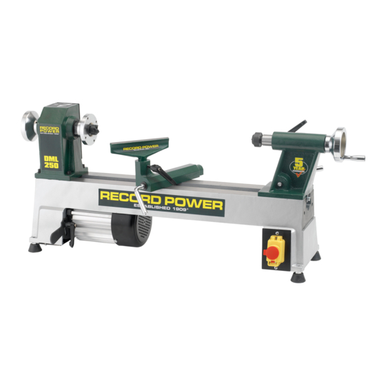
DML250 10" 5 Speed Cast Iron
Mini Lathe
15001 (UK version)
15002 (EP version)
Version 3.3
October 2016
It is important to register your product as soon as possible in order to receive efficient after sales
support and be entitled to the full 5 year guarantee. Your statutory rights are not affected.
Kg
Always wear safety glasses when
using woodworking equipment.
To register this product please visit
www.recordpower.info
Please see back cover for contact details.
Important
i
For your safety read instructions carefully before
assembling or using this product.
Always read the instructions
provided before using
Save this manual for future reference.
woodworking equipment.
1
Advertisement
Chapters
Table of Contents

Related Manuals for Record Power DML250


Summary of Contents for Record Power DML250
- Page 1 Original Instructions DML250 10” 5 Speed Cast Iron Mini Lathe 15001 (UK version) 15002 (EP version) Version 3.3 October 2016 To register this product please visit www.recordpower.info It is important to register your product as soon as possible in order to receive efficient after sales support and be entitled to the full 5 year guarantee.
-
Page 2: Table Of Contents
Contents of the Package Getting to Know Your Lathe Assembly Assembly of the Optional DML305/A Leg Stand 10 Assembly of the Optional DML305/L Extension Support and DML250 Bed Extension 11 Operation 12 Maintenance 13 Intended Use of the Lathe and Basic Woodturning Instructions... -
Page 3: Explanation Of Symbols
1. Explanation of Symbols The symbols and their meanings shown below may be used throughout this manual. Please ensure that you take the appropriate action wherever the warnings are used. Mandatory Instructions Read and fully understand the instruction manual before attempting to use the machine. -
Page 4: General Power Tool Safety Warnings
2. General Power Tool Safety Warnings WARNING: Read all safety warnings, instructions, illustrations e) Do not overreach. Keep proper footing and balance at all and specifications provided with this power tool. Failure to follow times. This enables better control of the power tool in unexpected all instructions listed below may result in electric shock, fire and/or serious situations. -
Page 5: Woodturning Lathe Safety Warnings
3. Woodturning Lathe Safety Warnings Safe Operation • Do not remount a work piece that has been turned between centres if the original centres have been altered or removed, unless you are deliberately Familiarise yourself with the machine turning eccentric work. •... -
Page 6: Record Power Guarantee
Guarantee should be made directly to Record Power or its Authorised Distributor Record Power guarantees that for a period of 5 years from the date (for details of the Authorised Distributor in your country please see of purchase the components of qualifying Products (see clauses 1.2.1 your Product manual or check www.recordpower.info for details). -
Page 7: Specifications
5. Specifications Voltage: 230 V Taper: 2 Morse Taper Frequency: 50 Hz Spindle travel: 44.5 mm Motor input P1: 0.375 kW Size: L902 x D267 x H375 mm Motor output P2: 0.25 kW Weight: 34 kg Motor speed: 1400 rpm Spindle Thread: M33 x 3.5 Full load current: 1.6 A Sound Pressure Level: No load 59.3 dB(A) -
Page 8: Getting To Know Your Lathe
7. Getting to Know Your Lathe 12 Tool rest holder Motor 13 Tool rest holder locking lever Motor securing lever 14 Tool rest locking lever Motor positioning lever Motor pulley access hatch 15 Revolving centre Headstock 16 Tailstock barrel Hand wheel 17 Tailstock Spindle pulley access hatch 18 Tailstock barrel locking lever... -
Page 9: Assembly
Securing the Lathe to a Solid Work Surface or Suitable Stand The DML250 can be used freestanding on a bench. If required, the lathe can be attached either to a solid work surface at least 25 mm thick, or a suitable stand, using the 4 mounting holes located at the base of the lathe as show in Figs 8.2 and 8.3. - Page 10 8. Assembly Fig 8.6 If the lathe is to be attached to a bench, spacers of at least 25 mm (1”) depth must be used at each end of the lathe to raise it from the bench surface and allow for movement of the motor, see Fig 8.6.
-
Page 11: Assembly Of The Optional Dml305/A Leg Stand
9. Assembly of the Optional DML305/A Leg Stand Contents of the Package Item Description Quantity Upright plinths Male cross brace Female cross brace M10 x 25 mm hex head screws M8 x 35 mm bolts, nuts and washers M10 x 80 mm bolts, nuts and washers Upright columns Bases... -
Page 12: Upright Plinths
9. Assembly of the Optional DML305/A Leg Stand Using an 18 mm wrench (not supplied) attach the upright column to the Fig 9.1 base using 2 M10 x 80 mm bolts, ensuring that there is an M10 washer between each bolt and the upright column and another M10 washer between each M10 nut and the base, Fig 9.1. -
Page 13: Assembly Of The Optional Dml305/L Extension Support And Dml250 Bed Extension
6 M10 x 80 mm bolts, nuts and washers x 6 7 Upright column 8 Base Contents of the DML250 Bed Extension Package 1 M10 x 30 mm bolts x 2 2 Washers x 2 3 Spring washers x 2... -
Page 14: Upright Columns
10. Assembly of the Optional DML305/L Extension Support and DML250 Bed Extension Assembly of the DML305/L Extension Support Fig 10.1 Attach the upright column to the base using 2 M10 x 80 mm bolts, ensuring that there is an M10 washer between each bolt and the upright column and another M10 washer between each M10 nut and the base, Fig 10.1. - Page 15 10. Assembly of the Optional DML305/L Extension Support and DML250 Bed Extension Assembly of the DML250 Bed Extension Fig 10.6 Before fitting the bed extension the retaining washer and bolt must be removed from the end of the lathe bed, as shown in Fig 10.6 using a 5 mm Retaining washer hex wrench.
-
Page 16: Operation
11. Operation Using the Faceplate Fig 11.1 The DML250 is supplied with an 83 mm (3 1/4”) faceplate which is already assembled to the machine as shown in Fig 11.1. The faceplate is designed for turning small to medium sized bowls. - Page 17 11. Operation Fitting the 4 Prong Drive Centre to the Headstock Fig 11.6 When turning between centres the 4 prong drive centre should be used in conjunction with the revolving centre. For details on turning between centres, Flat area please refer to the Intended use of the Lathe and Basic Woodturning of spindle Instructions chapter of the manual.
- Page 18 Please see the Maintenance section of the manual for full details. Changing the Spindle Speed The DML250 features a 5 step pulley system. The drive belt must be Fig 11.13 Tailstock spindle positioned on the corresponding pulleys as shown in Fig 11.14 to achieve...
- Page 19 11. Operation To access the motor pulley remove the cross head screw from the motor Fig 11.16 pulley access hatch cover using a cross head screwdriver (not supplied) and Screw remove the cover, Fig 11.16. washer Loosen the motor securing lever and raise the motor to its highest position using the motor positioning lever, Fig 11.17, and re-tighten the motor securing lever to hold it in place.
- Page 20 11. Operation Operating the Lathe Fig 11.20 To turn the lathe on, press the green switch marked ‘I’ on the switch situated on the lathe bed at the opposite end to the headstock, as shown in Fig 11.20. To stop the machine, press the red button marked ‘O’ on the control panel as shown in Fig 11.20.
-
Page 21: Maintenance
12. Maintenance Cleaning the Machine Fig 12.1 Avoid build up of wood shavings and dust by regularly cleaning the lathe with a soft cloth or brush. Retaining washer Adjustment of the Tool Rest Holder If the movement of the tool rest is unsatisfactory, either due to being too stiff and difficult to move or too easy to move and giving inadequate locking, the clamping action can be adjusted. - Page 22 12. Maintenance Fig 12.6 Screw and washer The machine must be unplugged from the power source while carrying out this procedure. Headstock Changing the Belt cover To replace the belt, the spindle shaft must be removed from the headstock. To access the spindle pulley remove the cross head screw and washer from the headstock cover using a cross head screwdriver (not supplied), and remove the cover, Fig 12.6.
- Page 23 12. Maintenance Once the spindle pulley is loose, carefully knock the spindle out of the Fig 12.11 headstock using a soft headed mallet as shown in Fig 12.11 by knocking firmly towards the tailstock end. Please note: The headstock features a circlip inside each recess that houses the bearings as shown in Fig 12.12.
- Page 24 12. Maintenance Cleaning the Tailstock Barrel Fig 12.16 It is advisable to periodically check the thread of the tailstock barrel lead screw for build up of residue and dust which could impair its movement. To access the lead screw, first remove the blind set screw of the handwheel using a 3 mm hex wrench as shown in Fig 12.16 and remove the hand- wheel to expose the rear of the lead screw, Fig 12.17.
- Page 25 12. Maintenance Push the tailstock barrel in as far as possible and re-attach the handwheel, Fig 12.21 ensuring the blind set screw is secured to the flattened area of the shaft as shown in Fig 12.21. Flattened area Blind set screw...
-
Page 26: Intended Use Of The Lathe And Basic Woodturning Instructions
13. Intended Use of the Lathe and Basic Woodturning Instructions Intended Use of the Lathe Fig 13.1 This lathe is designed for turning wood between centres or on the headstock (using appropriate accessories), for sanding and applying finishes to wood. It is not to be used for any other purpose. Doing so will invalidate the warranty and may cause serious harm to the user. - Page 27 13. Intended Use of the Lathe and Basic Woodturning Instructions Positioning the Tool Rest Fig 13.6 It is extremely important to ensure the tool rest is correctly positioned before turning on the lathe. Place the tool rest close to the timber, allowing enough room to manoeuvre the chisel with ease.
- Page 28 The guidelines above give basic instructions on some of the most common woodturning procedures. There are a wide variety of specialised chisels and many complementary accessories available for Record Power lathes which enable a huge variety of work to be created. For further instructions on more advanced safe and effective woodturning, please seek professional training.
-
Page 29: Dust Extraction
Record Power Extractors for 20 minutes every hour. 0.5 micron filtration Record Power offer a range of high quality dust extractors, we offer both drum and bag type extractors which filter down 0.5 micron providing protection from harmful fine dusts. All Record Power dust extractors and chip CX2000 Compact Chip Extractor collectors have 100 mm inlets and hoses. -
Page 30: Troubleshooting
15. Troubleshooting Warning: For your own safety, always turn off and unplug the machine before carrying out any troubleshooting. Problem Cause Solution Machine will not start, develop full power 1. Machine not plugged in. 1. Plug the machine in. or stalls. 2. -
Page 31: Electrical Connection And Wiring Diagram
It is important that the machine is effectively earthed. 230 V (Single Phase) Brown: Live (L) Replacement of a faulty power cord must be carried out by Record Power or Blue: Neutral (N) an approved qualified electrician. Green and Yellow:... -
Page 32: Parts Diagram And List
17. Parts Diagram and List... - Page 33 17. Parts Diagram and List Description Quantity Description Quantity Screw M5 x 10 mm Locking handle Headstock cover handle Motor Headstock cover retaining screw Switch Headstock cover Screw 4 x 30 mm Washer 6 mm Screw 4 x 25 mm Spring washer 6 mm Plate Hex.
-
Page 34: Eu Declaration Of Conformity
At: TUV Rheinland LGA Products GmbH, Tillystrasse 2, 90431, Nürnberg, Germany and complies with the relevant essential health and safety requirements. Signed............Dated: 01/06/2016 Andrew Greensted Managing Director Technical file held by Andrew Greensted, Record Power Ltd, Centenary House, 11 Midland Way, Barlborough Links, Chesterfield, Derbyshire, S43 4XA, United Kingdom... - Page 36 Woodworking Machinery and Accessories United Kingdom Eire Australia New Zealand Record Power Ltd Record Power Ltd Tools 4 Industry Tools 4 Industry Centenary House, 11 Midland Way Centenary House, 11 Midland Way Po Box 3844 Po Box 276079 Barlborough Links, Chesterfield...
Need help?
Do you have a question about the DML250 and is the answer not in the manual?
Questions and answers