Table of Contents
Advertisement
Original Instruction Manual
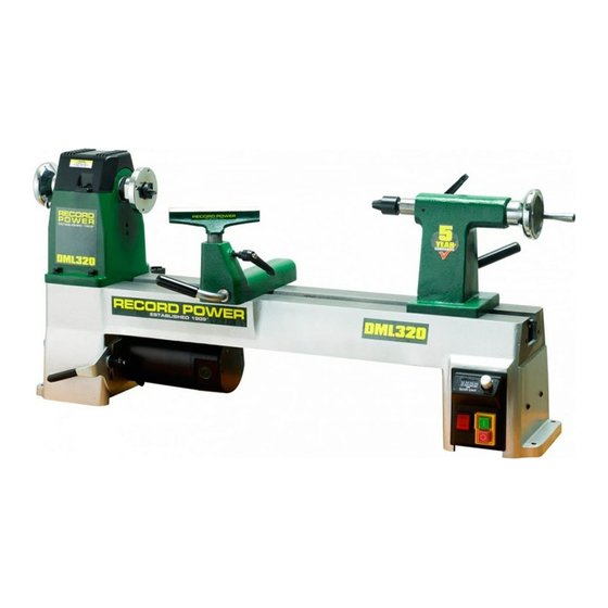
DML320 Cast Iron Electronic
Variable Speed Lathe
Version 3.3
December 2016
It is important to register your product as soon as possible in order to receive efficient after sales
support and be entitled to the full 5 year guarantee. Your statutory rights are not affected.
Kg
Always wear safety glasses when
using woodworking equipment.
To register this product please visit
www.recordpower.info
Please see back cover for contact details.
Important
i
For your safety read instructions carefully before
assembling or using this product.
Always read the instructions
provided before using
Save this manual for future reference.
woodworking equipment.
1
Advertisement
Table of Contents

Related Manuals for Record Power DML320


Summary of Contents for Record Power DML320
- Page 1 Original Instruction Manual DML320 Cast Iron Electronic Variable Speed Lathe Version 3.3 December 2016 To register this product please visit www.recordpower.info It is important to register your product as soon as possible in order to receive efficient after sales support and be entitled to the full 5 year guarantee. Your statutory rights are not affected.
-
Page 2: Table Of Contents
Contents Explanation of Symbols General Health and Safety Guidance Additional Health and Safety Guidance for Woodturning Lathes Record Power Guarantee Specifications Contents of the Package Getting to Know Your Lathe Assembly Assembly of the Optional DML305/A Leg Stand 10 Operation... -
Page 3: Explanation Of Symbols
1. Explanation of Symbols The symbols and their meanings shown below may be used throughout this manual. Please ensure that you take the appropriate action wherever the warnings are used. Mandatory Instructions Read and fully understand the instruction manual before attempting to use the machine. -
Page 4: General Health And Safety Guidance
2. General Health and Safety Guidance Ensure that you carefully read and fully understand the 6. The machine should be level and stable at all times instructions in this manual before assembly, installation and use • When using a leg stand or cabinet base that is designed to be fitted to of this product. - Page 5 2. General Health and Safety Guidance • If the work area is to be left unattended, all machinery should be switched additional support for a work piece that is longer or wider than the basic ‘OFF’ and isolated from the mains power supply. table, or to help feed, support, or pull the work piece.
-
Page 6: Additional Health And Safety Guidance For Woodturning Lathes
2. General Health and Safety Guidance the machine. 32. Have your machine repaired by a qualified person • This machine complies with the relevant safety rules and standards • A guard or other part that is damaged should be properly repaired appropriate to its type when used in accordance with these instructions or replaced by a qualified person unless otherwise indicated in this and with all of the standard safety guards and equipment in place. -
Page 7: Record Power Guarantee
Guarantee should be made directly to Record Power or its Authorised Distributor Record Power guarantees that for a period of 5 years from the date (for details of the Authorised Distributor in your country please see of purchase the components of qualifying Products (see clauses 1.2.1 your Product manual or check www.recordpower.info for details). -
Page 8: Specifications
5. Specifications Voltage: 230 V Spindle speeds: 250 - 3850 rpm Frequency: 50 Hz Taper: 2 Morse Taper Motor input P1: 0.75 kW Spindle travel: 63 mm Motor output P2: 0.55 kW Size: L1035 x W305 x D449 mm Motor speed: 2900 rpm Weight: 52 kg Full load current: 3 A Spindle Thread: M33 x 3.5... -
Page 9: Getting To Know Your Lathe
7. Getting to Know Your Lathe 9 10 Motor 14 Tool rest locking lever Motor securing lever 15 Revolving centre 16 Tailstock Motor positioning lever Motor pulley access hatch 17 Digital spindle speed readout Headstock 18 Spindle speed control knob Indexing lock 19 On / off switch 20 Forward / reverse switch... -
Page 10: Assembly
8. Assembly Fig 8.1 The machine must be unplugged and the power switch must be in the OFF position until the machine is assembled. Installing the Tool Rest to the Tool Rest Holder Loosen the locking lever and insert the tool rest into tool rest holder, Fig 8.1, adjust the height as required and tighten the locking lever, Fig 8.2. - Page 11 8. Assembly Secure the Lathe to a Solid Work Surface or Suitable Stand Fig 8.6 The lathe must be attached to a solid work surface at least 25 mm thick, or a suitable stand. Four mounting holes are located at the base of the lathe, 2 to the left of the headstock, Fig 8.6, and 2 to the right of the tailstock, Fig 8.7.
-
Page 12: Assembly Of The Optional Dml305/A Leg Stand
9. Assembly of the Optional DML305/A Leg Stand Contents of the Package Item Description Quantity Upright plinths Male cross brace Female cross brace M10 x 25 mm hex head screws M8 x 35 mm bolts, nuts and washers M10 x 80 mm bolts, nuts and washers Upright columns Bases... - Page 13 9. Assembly of the Optional DML305/A Leg Stand Using an 18 mm wrench (not supplied) attach the upright column to the Fig 9.1 base using 2 M10 x 80 mm bolts, ensuring that there is an M10 washer between each bolt and the upright column and another M10 washer between each M10 nut and the base, Fig 9.1.
-
Page 14: Operation
10. Operation Using the Faceplate Fig 10.1 The DML320 is supplied with an 81 mm (3”) faceplate which is already assembled to the machine as shown in Fig 10.1. The faceplate is designed for turning small to medium sized bowls. - Page 15 10. Operation Fitting the 4 Prong Drive Centre to the Headstock Fig 10.5 When turning between centres, the 4 prong drive centre should be used in conjunction with the revolving centre. For details on turning between centres, please refer to the Intended use of the Lathe and Basic Woodturning Flat area Instructions chapter of the manual.
- Page 16 10. Operation Fitting the Revolving Centre to the Tailstock Fig 10.9 When turning between centres, the revolving centre should be used in Tailstock spindle conjunction with the 4 prong drive centre. For details on turning between locking lever centres, please refer to the Intended use of the Lathe and Basic Woodturning Instructions chapter of the manual.
- Page 17 10. Operation Fig 10.14 Changing the Spindle Speed The DML320 features a 3 step pulley system. The drive belt should be SPINDLE PULLEY positioned on the corresponding pulleys as shown in Fig 10.14 to achieve the speed range required. Position...
- Page 18 Indexing Lock Fig 10.19 Indexing is a useful feature of the DML320 lathe, allowing accurate pattern work on projects such as straight fluting, grooving, drilling, lay out and more. The indexing system must only be used when the lathe is stationary and the power is turned off.
- Page 19 10. Operation Spindle Indexing Reference Chart Number of Index Angle Between Spindle Index The chart opposite gives a useful reference Positions Positions Numbers guide to basic indexing, showing the standard 360º 8 divisions of the indexing system, the angle 180º 1, 13 between positions and also the spindle index 120º...
- Page 20 10. Operation Error Codes Under certain conditions the digital display will show error codes to indicate the nature of a particular error with the machine or its use. Error Code Error Action Hardware Protection Mode Turn off the machine and re-start once the digital display has cleared.
-
Page 21: Maintenance
11. Maintenance Cleaning the Machine Fig 11.1 Avoid build up of wood shavings and dust by regularly cleaning the lathe with a soft cloth or brush. Adjustment of the Tool Rest Holder If the movement of the tool rest is unsatisfactory, either due to being too stiff and difficult to move or too easy to move and giving inadequate locking, the clamping action can be adjusted. - Page 22 11. Maintenance Changing the Belt Fig 11.6 To replace the belt, the spindle shaft must be removed from the headstock. This will allow the old belt to be removed and the new one installed. The machine must be unplugged and the power switch must be in the OFF position while carrying out this procedure.
- Page 23 11. Maintenance Using circlip pliers, remove the circlip positioned on the left of the spindle on Fig 11.11 the outside of the headstock as shown in Fig 11 .11. The spindle is held in place by 2 bearings, one can be seen on the outside left of the headstock as shown in Fig 11 .11 and the second is on the inside right of the headstock.
-
Page 24: Intended Use Of The Lathe And Basic Woodturning Instructions
12. Intended Use of the Lathe and Basic Woodturning Instructions Intended Use of the Lathe Fig 12.1 This lathe is designed for turning wood between centres or on the headstock (using appropriate accessories), for sanding and applying finishes to wood. It is not to be used for any other purpose. Doing so will invalidate the warranty and may cause serious harm to the user. - Page 25 12. Intended Use of the Lathe and Basic Woodturning Instructions Positioning the Tool Rest Fig 12.6 It is extremely important to ensure the tool rest is correctly positioned before turning on the lathe. Place the tool rest close to the timber, allowing enough room to manoeuvre the chisel with ease.
- Page 26 The guidelines above give basic instructions on some of the most common woodturning procedures. There are a wide variety of specialised chisels and many complementary accessories available for Record Power lathes which enable a huge variety of work to be created. For further instructions on more advanced safe and effective woodturning, please seek professional training.
-
Page 27: Dust Extraction
Record Power Extractors for 20 minutes every hour. 0.5 micron filtration Record Power offer a range of high quality dust extractors, we offer both drum and bag type extractors which filter down 0.5 micron providing protection from harmful fine dusts. All Record Power dust extractors and chip CX2000 Compact Chip Extractor collectors have 100 mm inlets and hoses. -
Page 28: Troubleshooting
14. Troubleshooting Warning: For your own safety, always turn off and unplug the machine before carrying out any troubleshooting. Problem Cause Solution 1. Machine not plugged in. 1. Plug the machine in. Machine will not start, develop full power or stalls. 2. -
Page 29: Electrical Connection And Wiring Diagram
15. Electrical Connection and Wiring Diagram Machines supplied for use in the UK are fitted with a 3 pin plug conforming fitted with a fuse conforming to BS1362 appropriate to the rating of the to BS1363, fitted with a fuse conforming to BS1362 and appropriate to the machine. -
Page 30: Parts Diagram And List
16. Parts Diagram and List... - Page 31 16. Parts Diagram and List Description Part Number Quantity Description Part Number Quantity JMWL1203010002A Tapping screw ST2D9X6D5GB845Z Hexagon socket cap screw M6X30GB70B Support bracket JMWL1203020012 Flat washer WSH6GB97D1B Speed sensor JMWL1203091001 Lock washer WSH6GB93B Headstock JMWL1203020005A Tool holder JL93010017-001S Spindle pulley JMWL1203020006A Cross pan head screw M6X12GB818B...
-
Page 32: Eu Declaration Of Conformity
EU Declaration of Conformity Cert No: EU / DML320 / 1 Record Power Ltd, Centenary House, 11 Midland Way, Barlborough Links, Chesterfield, Derbyshire, S43 4XA, United Kingdom declares that the machinery described:- 1. Type: Electronic Variable Speed Lathe 2. Model No: DML320 3. - Page 36 Woodworking Machinery and Accessories United Kingdom Eire Australia New Zealand Record Power Ltd Record Power Ltd Tools 4 Industry Tools 4 Industry Centenary House, 11 Midland Way Centenary House, 11 Midland Way Po Box 3844 Po Box 276079 Barlborough Links, Chesterfield...
Need help?
Do you have a question about the DML320 and is the answer not in the manual?
Questions and answers