Table of Contents
Advertisement
Original Instruction Manual
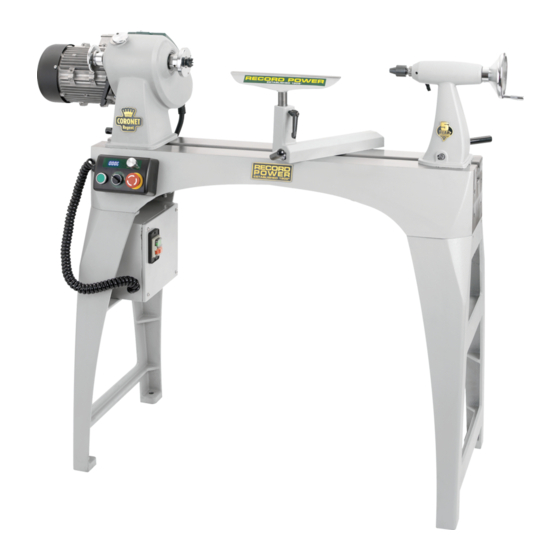
Coronet Envoy 16" Heavy-Duty Swivel-Head Cast Iron Variable Speed Lathe
Coronet Regent 18" Heavy-Duty Swivel-Head Cast Iron Variable Speed Lathe
Version 3.1
August 2019
Coronet Envoy shown
It is important to register your product as soon as possible in order to receive efficient after sales
support and be entitled to the full 5 year guarantee. Your statutory rights are not affected.
Kg
Always wear safety glasses when
using woodworking equipment.
To register this product please visit
www.recordpower.info
Please see back cover for contact details.
Important
i
For your safety read instructions carefully before
assembling or using this product.
Always read the instructions
provided before using
Save this manual for future reference.
woodworking equipment.
1
Advertisement
Table of Contents

Related Manuals for Record Power Coronet Series


Summary of Contents for Record Power Coronet Series
- Page 1 Original Instruction Manual Coronet Envoy 16" Heavy-Duty Swivel-Head Cast Iron Variable Speed Lathe Coronet Regent 18" Heavy-Duty Swivel-Head Cast Iron Variable Speed Lathe Version 3.1 August 2019 Coronet Envoy shown To register this product please visit www.recordpower.info It is important to register your product as soon as possible in order to receive efficient after sales support and be entitled to the full 5 year guarantee. Your statutory rights are not affected. Please see back cover for contact details. Important For your safety read instructions carefully before assembling or using this product. Always wear safety glasses when Always read the instructions using woodworking equipment. provided before using Save this manual for future reference. woodworking equipment.
-
Page 2: Table Of Contents
Contents Explanation of Symbols General Health and Safety Guidance Additional Health and Safety Guidance for Woodturning Lathes Record Power Guarantee Specifications Contents of the Package Getting to Know Your Lathe Assembly Assembly of the Optional Bed Extension 10 Assembly of the Optional Outrigger 11 Operation 12 Maintenance 13 Intended Use of the Lathe and Basic Woodturning Instructions 14 Dust Extraction 15 Troubleshooting 16 Electrical Connection and Wiring Diagram 17 Parts Lists and Diagrams EU Declaration of Conformity... -
Page 3: Explanation Of Symbols
1. Explanation of Symbols The symbols and their meanings shown below may be used throughout this manual. Please ensure that you take the appropriate action wherever the warnings are used. Mandatory Instructions Read and fully understand the instruction manual before attempting to use the machine. Indicates an instruction that requires particular attention Wear protective eyewear Use respiratory protective equipment Use hearing protection Use suitable protective footwear Use protective work gloves Warnings Indicates a risk of severe personal injury or damage to the machine Indicates a risk of severe personal injury... -
Page 4: General Health And Safety Guidance
2. General Health and Safety Guidance Ensure that you carefully read and fully understand the 6. The machine should be level and stable at all times instructions in this manual before assembly, installation and use • W hen using a leg stand or cabinet base that is designed to be fitted to of this product. Keep these instructions in a safe place for the machine, always ensure that it is securely fastened to the machine future reference. - Page 5 2. General Health and Safety Guidance • I f the work area is to be left unattended, all machinery should be switched additional support for a work piece that is longer or wider than the basic ‘OFF’ and isolated from the mains power supply. table, or to help feed, support, or pull the work piece. 13. Store machines safely when not in use • Do not attempt to machine more than one work piece at a time. • W hen not in use, machines should be stored in a dry place, out of reach of • W hen feeding the work piece towards the blade or cutting tool never children. Do not allow persons unfamiliar with these instructions or with position your hands in direct line of the cutting path. Avoid awkward the machine to operate it. operations and hand positions where a sudden slip could cause your hand 14. Do not overreach or fingers to move into the machining area. • C hoose a working position that allows your body to remain balanced and 23. Stay alert feed the work piece in to the machine without overreaching.
-
Page 6: Additional Health And Safety Guidance For Woodturning Lathes
2. General Health and Safety Guidance the machine. 32. Have your machine repaired by a qualified person • T his machine complies with the relevant safety rules and standards • A guard or other part that is damaged should be properly repaired appropriate to its type when used in accordance with these instructions or replaced by a qualified person unless otherwise indicated in this and with all of the standard safety guards and equipment in place. Only instruction manual. qualified persons using original spare parts should carry out repairs. • D o not use the machine if the switch does not turn the machine ‘ON’ Failure to do this may result in considerable danger to the user and and ‘OFF’. invalidation of warranty. • Have defective switches replaced by a qualified person. 33. Caution! Motor may become hot during use 31. -
Page 7: Record Power Guarantee
4. Record Power Guarantee Claims Procedure “Products” means the Products sold by Record Power subject to these terms and conditions; 2.1 I n the first instance please contact the Authorised Dealer who “Record Power” is Record Power Limited, whose company registration supplied the Product to you. In our experience many initial problems number is 4804158 and registered office address is Centenary House, 11 with machines that are thought to be due to faulty parts are actually Midland Way, Barlborough Links, Chesterfield, Derbyshire S43 4XA and sells solved by correct setting up or adjustment of the machines. A good through a network of Authorised Dealers; Authorised Dealer should be able to resolve the majority of these issues much more quickly than processing a claim under “Authorised Distributor” is the nominated importer for your region the guarantee. who will generally sell through a network of Authorised Dealers. Details of Authorised Distributors for specific countries can be found in the Product 2.2 A ny damage to the Product resulting in a potential claim under the manual or at www.recordpower.info; guarantee must be reported to the Authorised Dealer from which it was purchased within 48 hours of receipt. “Authorised Dealer” is a retailer or business authorised to sell Record 2.3 Power Products to end users. I f the Authorised Dealer who supplied the Product to you has been unable to satisfy your query, any claim made under this Guarantee Guarantee should be made directly to Record Power or its Authorised Distributor 1.1 R ecord Power guarantees that for a period of 5 years from the date... -
Page 8: Specifications
5. Specifications Coronet Envoy Voltage: 230 V Max. bowl diameter: 1000 mm (39”) Quill travel: 90 mm Frequency: 50 Hz Max. between centres: 610 mm (24”) Size: W1435 x D540 x H1190 mm Motor input P1: 1.5 kW Max. swing over bed: 410 mm (16”) Weight: 140 kg Motor output P2: 1.1 kW Spindle speeds: 250 - 3800 rpm Sound Pressure Level: No load < 83 dB(A) Motor speed: 1400 rpm Taper: 2 Morse Taper Sound Power Level: No load < 83 dB(A) Full load current: 4.5 A Spindle Thread: M33 x 3.5 Weight: 140 kg Coronet Regent... -
Page 9: Getting To Know Your Lathe
6. Contents of the Package Unpacking and Cleaning Tools Needed for Assembly (Not supplied) 1. C arefully lift the lathe from the carton and check that all of the components and contents have been included. Place parts on a protected surface. 24 mm wrench 2. C lean all rust protected surfaces with white spirit. Do not use gasoline, paint thinner, mineral spirits, etc. These may damage painted surfaces. Make sure the area is well ventilated and that there are no naked flames or sources of ignition. 3. S et packaging materials aside and do not discard until the machine has been set up and is running correctly. 7. Getting to Know Your Lathe Coronet Envoy shown 1 Control unit 8 4-prong drive centre 15 Tailstock hand wheel 2 Headstock locking shaft 9 Tool rest 16 Tailstock locking lever 10 Tool rest holder 17 Tailstock quill locking lever Motor... -
Page 10: Assembly
8. Assembly Fig 8.1 The machine must be unplugged and the power switch must be in the OFF position until the machine is assembled. The lathe is heavy and must be assembled by two people. Before mounting the lathe to the legs the tailstock, tool rest holder and headstock must be removed. Fig 8.2 Remove the end stop screws shown in Fig 8.1 using an 8 mm hex wrench. These are placed at both ends of the bed to stop accidental removal of the headstock, tailstock and tool rest holder. - Page 11 8. Assembly Place one of the legs on the bed as shown in Fig 8.6 and secure in place Fig 8.6 using 5 M10 x 30 mm screws, washers and spring washers as shown in Fig 8.7. Ensure the spring washer is placed between the washer and the screw head as shown in Fig 8.7. Repeat the process to assemble the remaining leg to the other end of the lathe bed, Fig 8.8. Place the assembled bed and legs upright as shown in Fig 8.9. Secure the lathe to a level floor using suitable fixings through the 4 fixing holes on the legs. Re-install the tool rest holder, tailstock and headstock, ensuring the locking levers and shafts are loosened to allow the clamping plates to be refitted to Fig 8.7 the bed as shown in Fig 8.10. Fig 8.8 Fig 8.9 Fig 8.10 Clamping plate Lathe bed...
- Page 12 8. Assembly Using the holes in the leg closest to the headstock as shown in Fig 8.11, Fig 8.11 attach the electrical enclosure box using 4 M6 x 25 mm socket pan head screws as shown in Fig 8.12 using a 4 mm hex wrench. Place the magnetic control unit in the desired position as shown in Fig 8.13. Fig 8.12 Fig 8.13...
-
Page 13: Assembly Of The Optional Bed Extension
9. Assembly of the Optional Bed Extension Contents of the Package Fig 9.1 Item Description Quantity C oronet Envoy / Regent bed extension M10 x 30 mm hex head socket screws M10 washers M10 spring washers Untapped holes Tapped holes Due to the weight of the bed extension it is recommended that one person holds the extension while a second threads Fig 9.2 the screws. -
Page 14: Assembly Of The Optional Outrigger
10. Assembly of the Optional Outrigger Contents of the Package Item Description Quantity Outrigger bracket Outrigger elbow Outrigger tool rest Curved tool rest Large ratchet handle Tool rest holder ratchet handle Outrigger bracket fixing plate Outrigger tool rest holder screw M12 x 80 hex head screw M10 x 60 hex head screw Washers Large washers Spring washers Attach the outrigger bracket fixing plate to the end of the bed using 2 M10 x Fig 10.1 60 screws, washers and spring washers as shown in Fig. 10.1. Leave a gap large enough to slide the outrigger bracket over. Ensure the spring washers are placed next to the screw head as shown. Slide the outrigger bracket over the screws as show in Fig 10.2, ensuring the fixing plate is on the inside of the bracket. Lathe bed Fig 10.2... - Page 15 10. Assembly of the Optional Outrigger Tighten the screws using a 17 mm wrench to secure the bracket in place. Fig 10.3 Ensure the protruding section of the bed sits within the recess of the bracket as shown in Fig 10.3. Lathe bed Place the outrigger elbow over the bracket as shown in Fig 10.4. Secure in place by passing the M12 x 80 screw through the top of the elbow and threading into a large ratchet handle as shown in Fig 10.4. Place a washer onto the screw before attaching the ratchet handle. Outrigger bracket Place the tool rest holder onto the elbow as shown in Fig 10.5 and secure in place using the tool rest holder screw, large ratchet handle and large washer as shown. Fig 10.4 Ensure the tool rest holder screw is located inside the recess as shown in Fig 10.6. Attach the tool rest holder ratchet handle as shown in Fig 10.7. Place the tool rest inside the holder and secure in place using the ratchet handle. Fig 10.5 Fig 10.6 Fig 10.7...
-
Page 16: Operation
11. Operation Using the Faceplate Fig 11.1 The Coronet Envoy and Regent are supplied with an 82 mm (3 ”) faceplate which is already assembled to the machine as shown in Fig 11.1. The faceplate is designed for turning small to medium sized bowls. Find the centre of the bowl blank and using dividers as shown in Fig 11.2, mark an 82 mm diameter circle from the centre of the blank. Place the faceplate over the scribed circle and attach it to the blank using 4 wood screws as shown in Fig 11.3. The length of wood screws used will vary depending on the size of bowl blank and intended finished thickness of Faceplate the base but the largest possible screws should be used to give maximum hold. Screw the faceplate onto the lathe spindle as shown in Fig 11.4. When beginning to turn the bowl, proceed with caution and ensure the blank is securely held to the faceplate. Fig 11.2 Fur further details on using the faceplate please refer to the Intended use of the Lathe and Basic Woodturning Instructions chapter of the manual. Before inserting tapered attachments into the headstock or quill ensure that the taper is clean and free of any waste material that may cause misalignment or vibration. - Page 17 11. Operation Firmly hold the hand wheel and turn the face plate anti-clockwise to remove Fig 11.6 as shown in Fig 11.6. Insert the drive centre into the headstock spindle, Fig 11.7. Removing the 4-Prong Drive Centre from the Headstock The operating bar is used to remove the drive centre from the headstock spindle. Place it into the hole positioned centrally in the hand wheel, at the opposite side of the headstock from the drive centre and give the drive centre a sharp knock to dislodge it, Fig 11.8. It is advisable to hold the drive centre to eliminate the risk of it being ejected with force and causing injury. Fitting the Revolving Centre to the Tailstock When turning between centres the revolving centre should be used in Fig 11.7 conjunction with the 4-prong drive centre. For details on turning between centres, please refer to the Intended use of the Lathe and Basic Woodturning Instructions chapter of the manual.
- Page 18 11. Operation Adjusting the Tool Rest Fig 11.11 To move the tool rest across the lathe bed, loosen the tool rest holder locking lever by turning it anti-clockwise, slide the tool rest holder to the desired Tool rest position and tighten the locking lever in a clockwise direction. locking lever To adjust the height of the tool rest loosen the tool rest locking lever, position the tool rest as required and re-tighten, Fig 11.11. Adjusting the Tailstock Loosen the tailstock locking lever to move the tailstock along the lathe bed Tool to the desired position and tighten the lever, Fig 11.12. rest holder locking lever To adjust the quill position, loosen the quill locking lever and turn the hand wheel. When the quill is in the desired position, re-tighten the locking lever, Fig 11.12. Fig 11.12 Hand wheel Adjustment of the Clamping Action of the Tool Rest Holder If movement of the tool rest holder or tailstock is unsatisfactory, either due to being too stiff and difficult to move or too easy to move and giving inadequate locking, the clamping action can be adjusted. Please see the...
- Page 19 11. Operation Loosen the motor tension lever and raise the motor to its highest position, Fig 11.16 Fig 11.16, and re-tighten to hold the motor in place. The drive belt will now be loose enough to move, Fig 11.17. Place the belt in the desired position, release the tension lever and carefully lower the motor. Turn the hand wheel by hand to check the grooves of the belt and pulleys are located correctly, Fig 11.18. The weight of the motor should give sufficient tension to the drive belt. Once the motor has been lowered, tighten the tension lever. If the belt slips during Tension lever operation it may be necessary to apply a little more tension. Indexing Indexing is a useful feature of the Coronet Enjoy and Regent, allowing accurate pattern work on projects such as straight fluting, grooving, drilling, Fig 11.17 lay out and more. The indexing system must only be used when the lathe is stationary and the power is turned off. The indexing system must not be used as a method of holding the spindle when removing accessories such as faceplates and chucks.
- Page 20 11. Operation Disengage the spindle lock by lifting the indexing dial and rotating to a Fig 11.21 Indexing dial position where it is not located in the recess then lowering, Fig 11.21. Spindle Indexing Reference Chart The chart opposite gives a useful reference guide to basic indexing, showing the standard 8 divisions of the indexing system, the angle between positions and also the spindle index positions to use. Recess Operating the Lathe Before turning the lathe on, ensure the off switch has been rotated clockwise and is in the raised position. To turn the lathe on, press the on switch as shown in Fig 11.22. Number of Index Angle Between Spindle Index To turn the lathe off, press the off switch. Positions Positions Numbers 360º To cut off power from the control box, press the off switch on the electrical 180º 1, 13 enclosure box as shown in Fig 11.23. 120º...
-
Page 21: Maintenance
12. Maintenance Cleaning the Machine Fig 12.1 Avoid build up of wood shavings and dust by regularly cleaning the lathe with a soft cloth or brush. Nylon locking nut Adjustment of Clamping Action of the Tool Rest Holder, Tailstock and Headstock If movement of any of these items is unsatisfactory, either due to being too stiff and difficult to move or too easy to move and giving inadequate locking, the clamping action can be adjusted. Remove the required item from the lathe bed by loosening the locking mechanism and sliding it off the bed. On the underside of the item is a bolt with a nylon locking nut which holds the clamp in place, Fig 12.1 (tool rest holder illustrated). If the clamping action is too low, turn the nut clockwise with 16 mm wrench Fig 12.2 and re-fit the tool rest holder to the lathe. If the clamping action is too high, turn the nut anti-clockwise and re-fit the tool rest holder to the lathe. Stiffness may also be caused by timber residue or other debris on the lathe bed. Changing the Belt The machine must be unplugged and the power switch must be in the OFF position when carrying out this procedure. - Page 22 12. Maintenance To remove the belt from the spindle pulley the spindle must be detached Fig 12.6 from the headstock. Pulley Spindle Sensor plate The spindle assembly is shown in Fig 12.6. Wave Remove the circlip shown in Fig 12.7 from the outside of the headstock using circlip pliers. washer Remove the two blind set screws of the sensor plate using a 3 mm hex wrench as shown in Fig 12.8. The spindle pulley features 4 blind set screws as shown in Fig 12.9. In each position there are 2 screws. Remove all 4 screws from the pulley. Bearings The sensor plate and pulley are now loose on the spindle, reducing risk of damage when the spindle is removed. Remove the hand wheel by unscrewing it clockwise. Fig 12.7 Circlip NOTE: The hand wheel features a left-hand thread. It may be necessary to hold the spindle in place using the 38 mm wrench as shown in Fig 12.10 and use the operating bar fitted to the hand wheel. Use a soft-headed mallet to carefully knock the spindle from the headstock housing.
- Page 23 12. Maintenance Fig 12.11 CAUTION: When re-fitting the spindle pulley, ensure it aligns with the motor pulley. Misaligned pulleys will wear the drive belt very quickly. Fig 12.11 shows the pulley misaligned. Fig 12.12 shows the pulley correctly aligned, To aid alignment, a rule can be placed flush against the side of the motor pulley as reference for the position of the spindle pulley. See Fig 12.13. The motor can now be locked back in position to place tension on the drive Fig 12.12 belt. Cleaning the Tailstock Barrel Remove the quill locking lever as shown in Fig 12.14.
- Page 24 12. Maintenance Remove the blind set screw from the hand wheel using a 3 mm hex wrench Fig 12.16 as shown in Fig 12.16. Remove the quill by pulling it forward out of the tailstock casting as shown in Fig 12.17. Unscrew the lead screw as shown in Fig 12.18. Remove all debris from the lead screw and quill to ensure optimum performance. Reassemble the tailstock assembly, ensuring the measurement scale on the quill faces upwards, Fig 12.19 and the recess is aligned with the blind set screw hole, Fig 12.20. Fig 12.17 NOTE: When refitting the hand wheel the blind set screw must be located on the flat area of the quill shaft as shown in Fig 12.19. Fig 12.18 Lead screw Quill...
-
Page 25: Intended Use Of The Lathe And Basic Woodturning Instructions
13. Intended Use of the Lathe and Basic Woodturning Instructions Intended Use of the Lathe Fig 13.1 This lathe is designed for turning wood between centres or on the headstock (using appropriate accessories), for sanding and applying finishes to wood. It is not to be used for any other purpose. Doing so will invalidate the warranty and may cause serious harm to the user. Health and Safety Please read the health and safety instructions contained in this manual and the specific health and safety instructions relating to woodturning. In addition, it is recommended to ensure your work area is adequately equipped with dust extraction and air filtration equipment. Fig 13.2 Respiratory equipment should also be used to greatly reduce lung exposure to harmful fine dust. Always establish the properties of the timber being turned and take extra care when working with harmful and carcinogenic materials. Eye protection must always be worn. Due to the nature of woodturning, shavings, dust and splinters can be thrown at fast speeds, making adequate eye protection essential. Mounting Timber to a Faceplate or Chuck Fig 13.3 Before mounting the workpiece to a faceplate or chuck, it is advisable to shape the timber into as cylindrical a profile as possible, see Fig 13.1. Turning unbalanced timber increases lathe vibration, the risk of it being thrown from the lathe, increased risk of chisel dig in and makes correct positioning of the tool rest difficult due to variable distances. - Page 26 13. Intended Use of the Lathe and Basic Woodturning Instructions Positioning the Tool Rest Fig 13.6 It is extremely important to ensure the tool rest is correctly positioned before turning on the lathe. Place the tool rest close to the timber, allowing enough room to manoeuvre the chisel with ease. Spin the timber by hand to ensure it does not come into contact with the tool rest. If the lathe is started without checking this and the timber hits the tool rest, there is a risk the timber could be thrown from the lathe and cause injury. Never attempt to reposition the tool rest while the lathe is in motion. Tool rest height is also important and varies depending on the chisel being used. When using a roughing gouge, the cutting edge should come into contact with the centre of the workpiece, see Fig 13.6. If using a skew chisel, the cutting edge should be applied approximately 3/8" (10 mm) above the centre height, see Fig 13.7. A spindle gouge's cutting edge should come into contact with the workpiece approximately 3/8" (10 mm) Fig 13.7 below its centre, see Fig 13.8. Using the Roughing Gouge The first step when turning between centres is invariably to 'rough out' the blank. This involves taking a square section blank and paring it down with a roughing gouge to a cylindrical profile, ready to shape into the final piece. Roughing gouges are usually sharpened to have the bevel at a 45º angle. Using the tool rest to support the blade, offer the blade to the workpiece at an angle, see Fig 13.9. When offering the roughing gouge to the workpiece, the bevel should be rubbing it, without cutting. To make a cut, gently raise the handle of the tool in order to bring the cutting edge into contact with the timber. Using light passes, move the blade outwards towards the same edge of the timber which the blade is facing, Fig 13.9. Never move the tool backwards, as this introduces the risk of splintering the wood and causing...
- Page 27 13. Intended Use of the Lathe and Basic Woodturning Instructions Using the Skew Chisel Fig 13.11 Skew chisels are available in both flat and oval profiles. The curved profile is favoured by many as it gives better results more easily. Skew chisels are ideal for creating beads, refining the profiles and can be used to create a final smooth finish to the workpiece. The skew chisel should be applied to the workpiece horizontally with the blade resting on the tool rest, Fig 13.11, again with the bevel rubbing the workpiece and raising the handle to take careful, controlled cuts. Further Operations The guidelines above give basic instructions on some of the most common woodturning procedures. There are a wide variety of specialised chisels and many complementary accessories available for Record Power lathes which enable a huge variety of work to be created. For further instructions on more advanced safe and effective woodturning, please seek professional training. Speeds of the Lathe To ensure the safest possible use of the lathe, it is important to understand which speeds are suited to which tasks. In general, the slower speeds should be used for the initial turning and roughing out of large pieces and the slowest speed should be used when large pieces are out of balance. This will reduce the possibility of the workpiece being thrown from the lathe. Medium speeds are ideally suited for general purpose work which doesn’t place heavy loads on the spindle of the lathes, for example when creating the profiles of spindles and some smaller bowl turning. The fastest speeds should be used only for small diameter work, where the size of workpiece is relatively small and therefore poses a lower risk of causing damage. Extra care should be taken when turning at the fastest speeds, using only a relatively light touch. When sanding, care should be taken to not burn the operator’s hands or the workpiece. It is recommended to not exceed the speed used for the last turning operation. If in doubt, use a slow speed.
-
Page 28: Dust Extraction
200 litre capacity, 2 x 1 kW motors, 0.5 micron filtration. Includes hose. problems related to wood dust. It is also necessary in order to ensure the waste producing machine performs safely and effectively. Some woods are CGV286 CamVac Series Compact Extractor extremely toxic and in addition to suitable dust extraction machines it is 36 litre capacity, 1 kW motor single or twin, 0.5 micron filtration. recommended that PPE such as respirators are also used. CGV286-WALL CamVac Series Wall Mounted Extractor Record Power Dust Extraction Machines 150 litre capacity, 1 kW motor single or twin, 0.5 micron filtration. Below is a summary of the Record Power range. Please visit your local stock- ist or go online for full details. CGV336 CamVac Series Medium Extractor 55 litre capacity, 1 kW motor single or twin, 0.5 micron filtration. DX1000 Fine Filter 45 Litre Extractor 45 litre capacity, 1 kW motor, 0.5 micron filtration. Includes hose. CGV386 CamVac Series Large Extractor 90 litre capacity, 1 kW motor twin or triple, 0.5 micron filtration. -
Page 29: Troubleshooting
15. Troubleshooting Warning: For your own safety, always turn off and unplug the machine before carrying out any troubleshooting. Problem Cause Solution 1. Machine not plugged in. 1. Plug the machine in. Machine will not start, develop full power or stalls. 2. Low voltage. 2. Check power supply to the machine. 3. Loose connection. 3. Check all external connections. 4. Circuit overloaded with electrical appliances. 4. Decrease the load on the circuit. 5. Circuit too long or undersized wires. 5. R educe the length of the wire or use a suitable diameter of cable. 6. C ircuit breaker does not have 6. H ave a qualified electrician install proper sized sufficient capacity. -
Page 30: Electrical Connection And Wiring Diagram
16. Electrical Connection and Wiring Diagram Machines supplied for use in the UK are fitted with a 3 pin plug conforming Never modify the fuse or fuse holder to accept fuses of a different type or to BS1363, fitted with a fuse conforming to BS1362 and appropriate to the size. current rating of the machine. Where the current rating of the machine exceeds 13 A at 230 V, or if the Machines supplied for use in other countries within the European Union are machine is designated for use on a 400 V 3 phase supply a connector fitted with a 2 pin Schuko plug conforming to CEE 7/7. conforming to BS4343 (CEE17 / IEC60309) will be used. Machines supplied for use in Australia and New Zealand are fitted with a 3 230 V machines will be fitted with a blue 3 pin connector. The wiring for this pin plug conforming to AS/NZS3112. type of this connector will be the same as shown above. In all cases, if the original plug or connector has to be replaced for any 400 V, 3 phase machines will be fitted with a red 4 or 5 pin connector. The reason, the wires within the mains power cable are colour coded as follows: wiring for this type of connector is as shown below: 230 V (Single Phase) Installation requirement for electrical system: Brown: Live (L) Electrical system providing a RCD with a maximum residual current of 0.03A should be provided. Installation of over voltage protection is needed. Blue: Neutral (N) Steady state voltage: 0.9-1.1 of nominal voltage (230V~). Green and Yellow: Earth (E) Frequency: 0.99-1.01 of nominal frequency continuously; 0.98-1.02 short time. The wire coloured brown must always be connected to the terminal marked HVF: ≤0.02 ‘L’ or coloured red. Site Operating Conditions The wire coloured blue must always be connected to the terminal marked ‘N’ or coloured black. a. A ltitude are not exceeding 1000m, The wire coloured green and yellow must always be connected to the b. M aximum ambient air temperature is +40 ºC, minimum ambient air terminal marked ‘E’ or with the earth symbol:... -
Page 31: Parts Lists And Diagrams
17. Parts Lists and Diagrams RCWL1601020000 机头箱组件 Sheet 10 11 18 19 25 26 27 28 Coronet Envoy and Regent Headstock Assembly No. Code Description No. Code Description JL93011100 Drive centre 31 YSH800114 Motor (Envoy) JMWL1203020010A 82 mm (3 ") faceplate 31 YSH900154 Motor (Regent) M6X8GB80B M6 x 8 hexagon set screw 32 RCWL1601020014 Locking handle RCWL1601020002 Spindle 33 RCWL1601020008... - Page 32 17. Parts Lists and Diagrams Coronet Envoy and Regent Bed Assembly No. Code Description M10X30GB70D1Z M10 x 30 hexagon socket head screw M10GB6170Z M10 hex nut RCWL1601010001 Lathe bed 铸铁支腿组件 Sheet 爆炸图明细表 序号 代号 名称 平垫圈 A级 WSH10GB97D1Z WSH10GB93Z 标准型弹性垫圈 M10X30GB70D1Z 内六角圆柱头螺钉 RCWL1601101007 铸铁支腿 WL3040A100102 地脚 Coronet Envoy and Regent Leg Stand Assembly No.
- Page 33 17. Parts Lists and Diagrams Coronet Envoy and Regent Tailstock Assembly No. Code Description JL93031000A Revolving centre JMWL1203041100 Tailstock barrel JMWL1203041000 Ratchet handle RCWL1601040002 Cam lock handle CLP18GB894D1B Circlip ZTSL-D120-d15A Tailstock hand wheel M6X8GB80B M6 x 8 Hexagon socket set screw JL93030007 Hand wheel handle JMWL1203040007 Spring washer 10 JL93030008 Screw 11 M10GB889D1ZF M10 Hexagon lock nut 12 RCWL1601040004 Tailstock clamp 13 JL93030011 Compression spring 14 RCWL1601040003 Bolt 15 CLP14GB894D1B...
- Page 34 17. Parts Lists and Diagrams Coronet Regent Electrical Enclosure Box Assembly No. Code Description RCWL1601092100 Controller box ADD15D8 Bellows joint (M16) RCWL1801091000 控制器组件 Sheet JL91046100 M20 cable gland RCWL1601090003 Pan head club screw RCWL1601090001 Cover plate DV1-128D0FB-C20C Transducer M6X20GB70D2Z M6 x 20 Hexagon socket button head screw JL91046100A M20 Cable gland M4X10GB823Z M4 x 10 cross pan head screw 10 KJD12-10F-230V Electromagnetic switch RCWL1601091000 开关盒组件 Sheet Coronet Envoy and Regent Control Unit Assembly No.
- Page 35 17. Parts Lists and Diagrams Coronet Envoy and Regent Optional Bed Extension No. Code Description M10X30GB70D1Z M10 x 30 hexagon socket head screw WSH10GB93Z Spring washer WSH10GB97D1Z Flat washer RCWL1601030001 Extension bed WSH6GB96D1Z Large washer M6X16GB70D1Z M6 x 16 hexagon socket head screw M8X10GB77B M8 x 10 hexagon socket set screw M5X25GB77B M5 x 25 hexagon socket set screw M8X20GB70D2Z M8 x 20 hexagon socket button head screws 10 RCWL1601030002 Supporting plate 050000 后旋组件 Sheet 爆炸图明细 序号 代号 M12X80GB5783Z RCWL1601050003 RCWL1201030100 JMWL1203041000 Coronet Envoy and Regent Optional Outrigger...
-
Page 36: Eu Declaration Of Conformity
EU Declaration of Conformity Cert No: EU / Coronet Envoy and Coronet Regent / 1 Record Power Ltd, Centenary House, 11 Midland Way, Barlborough Links, Chesterfield, Derbyshire, S43 4XA, United Kingdom declares that the machinery described:- 1. Type: Wood Lathe 2. Model No: Coronet Envoy and Coronet Regent 3. Serial No ..............Will conform with the following standards: MACHINERY DIRECTIVE 2006/42EC ADDITIONAL USED EC DIRECTIVES: EMC Directive 2014/30/EU USED HARMONIZED STANDARDS: EN 60204-1:2018 EN ISO 12100: 2010 EN 55014-1:2017 EN 55014-2:2015 EN 61000-3-2: 2014 EN 61000-3-3: 2013 and complies with the relevant essential health and safety requirements and conforms to the machinery example for which the EC Type-Examination Certificate Numbers AE50443426 0001 and AM50442976 0001 has been issued. Signed............Dated: 01/08/2019 Andrew Greensted Managing Director Technical file held by Andrew Greensted, Record Power Ltd, Centenary House, 11 Midland Way, Barlborough Links, Chesterfield, Derbyshire, S43 4XA,... - Page 38 Woodworking Machinery and Accessories Record Power Ltd, Centenary House, 11 Midland Way, Barlborough Links, Chesterfield, Derbyshire S43 4XA Tel: +44 (0) 1246 571 020 Fax: +44 (0) 1246 571 030 www.recordpower.co.uk To register a product and find your local stockist visit recordpower.info Made in China...
Need help?
Do you have a question about the Coronet Series and is the answer not in the manual?
Questions and answers