
Related Manuals for Brother FAX-545


Summary of Contents for Brother FAX-545
- Page 1 FACSIMILE EQUIPMENT SERVICE MANUAL MODELS: FAX-575 FAX-T102/T104/T106 FAX-817/827/837MC FAX-878 Confidential...
- Page 2 © Copyright Brother 2008 All rights reserved. No part of this publication may be reproduced in any form or by any means without permission in writing from the publisher. All product and company names mentioned in this manual are trademarks or registered trademarks of their respective holders.
- Page 3 Preface This Service Manual is intended for use by service personnel and details the specifications, construction, theory of operation, and maintenance for the Brother machines noted on the front cover. It includes information required for troubleshooting and service--disassembly, reassembly, and lubrication--so that service personnel will be able to understand machine functions, repair the machine in a timely manner and order spare parts as necessary.
- Page 4 (EEPROM) mounted on the main PCB. If the main PCB is replaced, therefore, you will need to set up the proper customizing code with the machine in the maintenance mode. Customizing codes come with the firmware data provided by Brother Industries. Appendix 4...
- Page 5 If the machine becomes hot, releases smoke, or generates any strong smells, immediately unplug the machine from the electrical socket. Call your Brother dealer or Brother Customer Service. If metal objects, water or other liquids get inside the machine, immediately unplug the machine from the electrical socket.
- Page 6 DO NOT use the machine if the power cord is frayed or damaged, doing so may cause a fire. IMPORTANT SAFETY INSTRUCTION When using your telephone equipment, basic safety precautions should always be followed to reduce the risk of fire, electric shock and injury to persons, including the following: 1.
- Page 7 CHAPTER PARTS NAMES & FUNCTIONS Confidential...
- Page 8 CHAPTER 1 PARTS NAMES & FUNCTIONS This chapter contains external views and names of components and describes their functions. Information about the keys on the control panel is included to help you check operation or make adjustments. CONTENTS OUTLINE ......................... 1-1 CONTROL PANEL ......................
-
Page 9: Outline
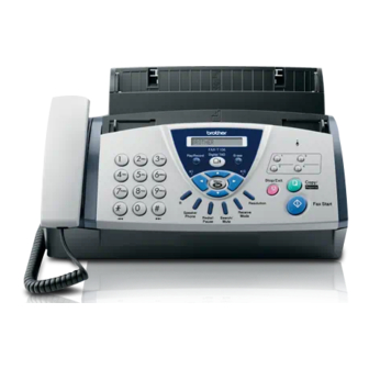
1.1 OUTLINE Front view FAX-575/FAX-T102/FAX-T104/FAX-T106/FAX-817/FAX-827/FAX-837MC FAX-878 1 - 1 Confidential... -
Page 10: Control Panel
Rear view (11) AC power connector (12) External telephone line socket (not for UK) (13) Telephone line socket Name Description Power cord Use to connect the fax machine to the electrical socket. Telephone line cord Connect the fax machine to a telephone wall socket. Telephone handset Use when receiving or making voice calls. -
Page 11: Control Panel
1.2 CONTROL PANEL FAX-T106/FAX-837MC The model of Fax-T106 is represented to indicate the illustration and description 1. LCD (Liquid Crystal Display) 4. R Displays messages on the screen to help you set up Use this key to gain access to an outside line and/or and operate your fax machine. - Page 12 7. Search/Mute 14. Erase Lets you look up numbers stored in the dialing Lets you delete voice messages, all fax messages or memory, lets you put calls on hold and lets you dial all messages. stored numbers by pressing # and a two-digit number.
- Page 13 FAX-575/FAX-T102/FAX-T104/FAX-817/FAX-827 The model of Fax-T104 is represented to indicate the illustration and description 1. LCD (Liquid Crystal Display) 4. Tel Displays messages on the screen to help you set up Use to toggle the line between handset and monitor and use your fax machine. speaker.
- Page 14 7. Receive Mode 13. Navigation Keys Use to select how your fax machine will handle Menu/Set incoming calls. The same key is used for menu and set operations. Lets you access the menu to program and store your settings in the fax machine. 8.
- Page 15 FAX-878 The model of Fax-878 is represented to indicate the illustration and description 1. LCD (Liquid Crystal Display) 4. Dial Pad Displays messages on the screen to help you set up Use these keys to dial telephone and fax numbers and use your fax machine.
- Page 16 7. Stop/Exit 13. Redial/Pause Stops a fax, cancels an operation or exits from the Redials the last number you called. It also inserts a menu. pause in Quick-Dial numbers. 8. Copy/Reports 14. Navigation Keys: With document in the ADF: Makes a copy. Menu/Set Without document in the ADF: Lets you access the The same key is used for menu and set operations.
- Page 17 1.3 COMPONENTS The machine consists of the following major components: *1 Not provided on the FAX-T102. *2 FAX-T102 *3 FAX-837MC/FAX-T106 1 - 9 Confidential...
-
Page 18: Specifications
CHAPTER SPECIFICATIONS Confidential... - Page 19 CHAPTER 2 SPECIFICATIONS This chapter lists the specifications of each model, which enables you to make a comparison of different models. CONTENTS GENERAL........................2-1 2.1.1 General Specifications..................2-1 2.1.2 Paper Specifications for the Paper Tray.............. 2-2 SPECIFICATIONS LIST ....................2-3 Confidential...
-
Page 20: General
2.1 GENERAL 2.1.1 General Specifications Desktop facsimile transceiver Type 512 KB Memory Capacity 64 g/m – 90 g/m : Up to 30 sheets Paper Tray 64 g/m – 90 g/m : Up to 20 sheets Paper Output Line Thermal with Ribbon Printer Type 16 characters x 1 Line LCD (Liquid Crystal Display) -
Page 21: Paper Specifications For The Paper Tray
FAX-878 FAX-T104: 2.7 kg (incl. accessories) Weight FAX-T106: 2.8 kg (incl. accessories) FAX-878: 2.8 kg (incl. accessories) 2.1.2 Paper Specifications for the Paper Tray : Letter/Legal Size Paper capacity of paper tray Paper weight Number of sheets 17 lb to 20 lb Up to 50* sheet 24 lb Up to 30 sheet... -
Page 22: Specifications List
2.2 SPECIFICATIONS LIST (1/4) FAX-T102 (w/o HS) Model Name FAX-575 FAX-T106 FAX-T104 GENERAL Print Engine Thermal Transfer Thermal Transfer Thermal Transfer Back up Clock 9 hours 15 hours 10-35 10-35 10-35 Operating Environment Temperature degree centigrade degree centigrade degree centigrade Humidity 20-80% 20-80%... - Page 23 (2/4) FAX-T102 (w/o HS) Model Name FAX-575 FAX-T106 FAX-T104 Modem Speed 9600 9600 14400 Transmission Speed Approx.15 sec. Approx.15 sec. Approx. 9 sex. ITU-T Group Coding Method Fax/Tel Switch Super Fine Gray Scale 64 levels 64 levels 64 levels Contrast Auto/Light/Dark Auto/Light/Dark Auto/Light/Dark...
-
Page 24: Table Of Contents
(3/4) FAX-817 Model Name FAX-837MC FAX-878 FAX-827 GENERAL Print Engine Thermal Transfer Thermal Transfer Thermal Transfer 48 hours 48 hours Back up Clock 48 hours *9 hours for TUR *15 hours for TUR 5-35 5-35 5-35 Operating Environment Temperature degree centigrade degree centigrade degree centigrade Humidity... - Page 25 (4/4) FAX-817 Model Name FAX-837MC FAX-878 FAX-827 Modem Speed 9600 14400 9600 Transmission Speed Approx.15 sec. Approx. 9 sex. Approx.15 sec. ITU-T Group Coding Method Fax/Tel Switch Super Fine Gray Scale 64 levels 64 levels 64 levels Contrast Auto/Light/Dark Auto/Light/Dark Auto/Light/Dark Smoothing Dual Access...
-
Page 26: Theory Of Operation
CHAPTER THEORY OF OPERATION Confidential... - Page 27 CHAPTER 3 THEORY OF OPERATION This chapter gives an overview of the scanning and printing mechanisms as well as the sensors, actuators, and control electronics. It aids in understanding the basic principles of operation as well as locating defects for troubleshooting. CONTENTS OVERVIEW ........................
-
Page 28: Overview
3.1 OVERVIEW *1: Not provided on the FAX-T102. *2: Model with battery: FAX-T106/FAX-837MC Confidential... -
Page 29: Mechanical Components
3.2 MECHANICAL COMPONENTS This machine consists of the following mechanisms and uses a single motor and various sensors. Scanning Mechanism - Document feeding & ejecting mechanism - Document scanning mechanism Printing Mechanism - Paper feeding and registration mechanism - Printing and paper ejecting mechanism Power Transmission Switching Mechanism Sensors and Actuators Recording paper... -
Page 30: Scanning Mechanism
3.2.1 Scanning Mechanism The scanning mechanism consists of the automatic document feeder (ADF), document separation roller, CIS unit (scanner), document ejection roller, and document sensors. (For details about the sensors, refer to Section 3.2.4.) Document feeding and ejecting mechanism Placing documents face down in the ADF and starting the scanning operation activate the drive motor so that the ADF (consisting of the document separation roller and ADF parts) feeds the documents into the machine, starting from the bottom (first page), page by page. -
Page 31: Power Transmission Switching Mechanism
3.2.3 Power Transmission Switching Mechanism This machine has a single drive motor whose power transmission route can be switched by the planetary gear system and by changing the motor rotation direction. This switching allows the machine to function in five operation modes—scanning, paper feeding, recording, paper ejecting, and copying modes. -
Page 32: Sensors And Actuators
3.2.4 Sensors and Actuators This machine uses the following photosensors and microswitches. Sensor Name Sensor Type Location Document front sensor Microswitch (SEN2) On the control panel PCB Document rear sensor Photosensor (SEN1) Cover open sensor Microswitch (SW2) On the sensor PCB Hook switch* Microswitch (SW1) Registration sensor... - Page 33 *Not provided on the FAX-T102. Sensors and Actuators Locations Confidential...
-
Page 34: Control Electronics
3.3 CONTROL ELECTRONICS 3.3.1 Components The following illustration shows the hardware components for this machine. The corresponding connection diagram appears in Appendix 5. Handset 4-pin Line 2-pin MJ NCU PCB External telephone 2-pin MJ 9-pin 15-pin Ribbon switch 2-pin Recording head 9-pin Speaker 2-pin... - Page 35 CHAPTER TRANSFER OF DATA LEFT IN THE MACHINE TO BE SENT FOR REPAIR Confidential...
- Page 36 CHAPTER 4 TRANSFER OF DATA LEFT IN THE MACHINE TO BE SENT FOR REPAIR This chapter describes how to transfer data left in the machine to be sent for repair. The service personnel should instruct end users to follow the transfer procedure given in this chapter if the machine at the user site cannot print received data due to the printing mechanism defective.
-
Page 37: Stations
4.1 TRANSFERRING RECEIVED FAX DATA When the machine at the user site requires to be repaired, unplugging the power cord from the wall socket for sending the machine for repair will lose received FAX data if unprinted and left in the machine. - Page 38 CHAPTER DISASSEMBLY/REASSEMBLY AND LUBRICATION Confidential...
- Page 39 CHAPTER 5 DISASSEMBLY/REASSEMBLY AND LUBRICATION This chapter details procedures for disassembling and reassembling the machine together with related notes. The disassembly order flow provided enables you to see at a glance the quickest way to get to component(s) involved. At the start of a disassembly job, you check the disassembly order flow that guides you through a shortcut to the object components.
- Page 40 5.1.14 Ribbon Switch and Grounding Plate..............5-38 5.1.15 Speaker......................5-39 5.1.16 Recorder Frame....................5-40 5.1.17 Routing of the Harnesses .................. 5-41 LUBRICATION ......................5-42 Confidential...
-
Page 41: Disassembly/Reassembly
5.1 DISASSEMBLY/REASSEMBLY Safety Precautions To prevent the creation of secondary problems by mishandling, observe the following precautions during maintenance work. (1) Before starting disassembly/reassembly jobs, unplug the power cord and telephone line. In particular, when having access to the power supply inside the machine, make sure that the power cord is unplugged from the electrical outlet;... -
Page 42: Tightening Torque
Tightening Torque Location of screw Screw type Q'ty Tightening torque N•m (kgf•cm) 0.69 ±0.2 (7 ±2) Cover stopper link Taptite, pan B M4x6D10 0.39 ±0.2 (4 ±2) Paper chute ASSY Taptite, cup B M3x8 0.39 ±0.2 (4 ±2) Document chute ASSY Taptite, cup B M3x8 0.39 ±0.2 (4 ±2) ADF parts... -
Page 43: Preparation
Preparation Prior to proceeding with the disassembly procedure, (1) Unplug - the power cord from the electrical outlet and the machine, - the modular jack of the telephone line from the machine, - the modular jack of the curled cord* (and remove the handset*), and - the modular jack of the external telephone set if connected (not shown below). -
Page 44: Disassembly Flowchart
Disassembly Flowchart 5.1.1 5.1.2 * For models except FAX-T102 Cover stopper link Handset mount ** For FAX-T102 Cover open sensor actuator Hook switch actuator Dummy mount Cover open sensor actuator 5.1.2 Top cover ASSY 5.1.3 Separation roller gear 29 5.1.3 Paper chute ASSY 5.1.4 5.1.4... -
Page 45: Handset Mount* (Dummy Mount**), Hook Switch Actuator, And Cover Open Sensor Actuator
5.1.1 Handset Mount* (Dummy Mount**), Hook Switch Actuator, and Cover Open Sensor Actuator *For models except FAX-T102, **For FAX-T102 (1) Open the top cover by lifting the cover open lever. (2) Press the inside of the handset mount* (or dummy mount**) to unlatch and twist it in the direction of the arrow shown below. - Page 46 (3) To remove the hook switch actuator* or cover open sensor actuator from the handset mount*, pull the corresponding actuator support outwards and lift up the actuator. The corresponding actuator spring also comes off. Cover open sensor actuator Hook switch actuator* Actuator spring* Actuator spring Actuator support Handset mount* Actuator support Reassembling Notes •...
-
Page 47: Cover Stopper Link And Top Cover Assy
5.1.2 Cover Stopper Link and Top Cover ASSY (1) Remove the screw from the cover stopper link. Pull the link outwards to release it from the top cover ASSY and then turn it to the front and release it from the boss on the main cover. Taptite, pan B M4x6D10 Top cover ASSY... - Page 48 (2) Disconnect the relay connector of the panel-main harnesses while supporting the top cover ASSY by hand. (3) Remove the top cover ASSY to the rear. Top cover ASSY Panel-main harness (upper) Panel-main harness (lower) Relay connector Panel-main harness (lower) Cable guide Main cover Routing the panel-main harness (lower) Reassembling Notes...
-
Page 49: Disassembly Of The Top Cover Assy (Separation Roller Gear 29, Paper Chute Assy, And Top Cover Sub Assy)
5.1.3 Disassembly of the Top Cover ASSY (Separation roller gear 29, paper chute ASSY, and top cover sub ASSY) (1) Place the top cover ASSY upside down. (2) Lightly press the lock arm and pull out the separation roller gear. (3) Remove the three screws from the paper chute ASSY. - Page 50 Reassembling Notes • When mounting the paper chute ASSY on the top cover sub ASSY, follow the steps below. 1) Lightly press the lock arm and pull out the separation roller gear 29 ( ) that should be temporarily mounted for correct positioning of the document separation roller when the document chute ASSY has been mounted in Section 5.1.5.
-
Page 51: Disassembly Of The Paper Chute Assy (Chute Film, Sheet Feeder Parts, Paper Ejection Roller Assy, Registration Sensor Actuator, Lock Bar & Levers, And Platen)
5.1.4 Disassembly of the Paper Chute ASSY (Chute film, sheet feeder parts, paper ejection roller ASSY, registration sensor actuator, lock bar & levers, and platen) Chute film (1) Remove the chute film from the paper chute ASSY only when it should be replaced. Attaching a new chute film Ribs Chute film... - Page 52 Sheet feeder parts (SF leaf spring, separation pad, film, support, plate, and coil spring) and paper ejection roller ASSY (2) Turn the paper chute ASSY rightside up. (3) Lightly pull the lock arm to the rear and push up the SF leaf spring with a flat screwdriver, taking care not to deform it.
- Page 53 (4) Press the both ends of the SF separation pad support inwards and take it out of the paper chute ASSY. The SF coil spring also comes off. (5) Remove the SF separation pad and film from its support. (6) Lightly press the lock arm and pull out the paper ejection roller ASSY. Also remove gear 10. NOTE: Take care not to lose gear 10.
- Page 54 Registration sensor actuator and gears 24 (8) Lightly press the lock arm, lift up the left end of the registration sensor actuator and take it out to the right. (9) Remove gears 24 by releasing their latches. Registration sensor actuator Paper chute ASSY (Rear) Lock arm Latches Gears 24...
- Page 55 Lock bar and levers (10) Release the latch of the lock lever R (dark gray) and pull it out. The lock spring also comes off. (11) Pull out the lock bar. (12) Release the latch of the lock lever L (white) and pull it out. Setting the lock spring Paper chute ASSY ...
-
Page 56: Disassembly Of The Top Cover Sub Assy (Paper Separation Roller, Document Chute Assy, Document Separation Roller, Adf Parts, White-Level Reference Film, Control Panel Assy, And Document Rear Sensor Actuator)
5.1.5 Disassembly of the Top Cover Sub ASSY (Paper separation roller, document chute ASSY, document separation roller, ADF parts, white-level reference film, control panel ASSY, and document rear sensor actuator) Paper separation roller (1) Lightly press the lock arm, slide the paper separation roller to the left and lift it up. Paper separation roller Lock arm (Front) - Page 57 Reassembling Note 1: Before mounting the document chute ASSY, be sure to slide the paper guides outwards to the A4 size position. Reassembling Note 2: Before mounting the document chute ASSY, temporarily engage the separation roller gear 29 with the right end of the document separation roller shaft for correct positioning of the document separation roller.
- Page 58 Document separation roller (3) Remove the document separation roller. (4) Unlatch the document support and push it down. Latches on the document support Document support Document chute Document support Document separation roller ADF parts (5) Remove the screw and disassemble the ADF parts as shown below. Taptite, pan B M3x6 Correct Wrong ADF leaf spring...
- Page 59 White-level reference film (6) Remove the white-level reference film from the top cover only when it should be replaced. Attaching a new white-level reference film Align the left and rear edges Top cover of the white-level reference White-level film with this rib. reference film (Front) (Front) Top cover (placed upside down) Reassembling Note: Once removed, the white-level reference film will become unusable and a new one will have to be put back in.
- Page 60 Control panel ASSY and document rear sensor actuator (7) Remove the screw from the top cover. (8) Unhook the top cover from the five latches* provided on the control panel ASSY. *FAX-878 has two latches. (9) Turn the document rear sensor actuator to the rear, slide it to the left, and take it out of the top cover.
-
Page 61: Disassembly Of The Control Panel Assy (Control Panel Pcb, Microphone*, Rubber Keypad, Control Panel, And Lcd)
5.1.6 Disassembly of the Control Panel ASSY (Control panel PCB, microphone*, rubber keypad, control panel, and LCD) *FAX-837MC/FAX-T106 FAX-575/FAX-T102/FAX-T104/FAX-T106/FAX-817/FAX-827/FAX-837MC (1) Disconnect the panel-main harness (upper) from the control panel PCB. (2) Unlock the LCD connector and disconnect the LCD flat cable. NOTE: After disconnecting the flat cable(s), check that each cable is not damaged at its end or short-circuited. - Page 62 (5) Pull the lock arms outwards and take out the LCD while pulling the LCD flat cable gently. Lock arm LCD flat cable Lock arm Reassembling Notes • Before setting the LCD back to the control panel, wipe fingerprints or dust off the LCD surface and control panel window with a soft cloth.
- Page 63 FAX-878 (1) Disconnect the panel-main harness (upper) from the control panel PCB. (2) Unlock the LCD connector and disconnect the LCD flat cable. (3) Unlatch the control panel PCB and remove the PCB. NOTE: After disconnecting the flat cable(s), check that each cable is not damaged at its end or short-circuited.
- Page 64 (4) Pull the lock arms outwards and take out the LCD while pulling the LCD flat cable gently. Reassembling Notes • Before setting the LCD back to the control panel, wipe fingerprints or dust off the LCD surface and control panel window with a soft cloth. •...
-
Page 65: Sensor Pcb
5.1.7 Sensor PCB (1) Remove the screw from the sensor PCB. (2) Disconnect the sensor-main harness from the sensor PCB. (3) Unlatch the sensor PCB from the main cover. Taptite, cup B M3x10 Sensor-main harness Sensor PCB Main cover Latch Confidential 5-25... -
Page 66: Recording Head Assy
5.1.8 Recording Head ASSY (1) While pressing the lock arms on the main cover, push down both ends of the recording head ASSY and move it to the rear to release the tabs from the cutouts provided in the recorder frame. NOTE: Do not press the center of the recording head ASSY. -
Page 67: Bottom Plate
5.1.9 Bottom Plate (1) Turn the main cover upside down. (2) Remove the six screws (five "a" screws and one "b" screw) from the bottom plate. (3) Slightly lift up the bottom plate and release the grounding wire (screw "c"). "a"... -
Page 68: Drive Unit And Motor
5.1.10 Drive Unit and Motor (1) Disconnect the motor harness and cam switch harness from the main PCB. (2) Turn the main cover rightside up. (3) Remove the two screws and lift the drive unit up and out of the main cover. Drive unit Taptite, cup B M3x10 Cam switch harness... - Page 69 (4) Remove two screws "d" to release the motor chassis. (5) Remove screw "e" to release the drive motor from the motor chassis. (6) Unlatch the cam switch. Drive gear frame "e" Latches "d" Cam switch "d" Motor chassis Bosses on the drive gear frame Drive motor Drive motor Motor chassis Bosses on the drive gear frame "d": Taptite, cup B M3x8 "e": Taptite, cup S M3x6...
- Page 70 Reassembling Notes • As shown below, route the cam switch harness on the drive gear frame. After that, check that its lead wires lie below the top of the guide bosses. • When mounting the drive motor to the motor chassis, face the harness side as shown on the previous page.
-
Page 71: Document Ejection Roller And Pinch Rollers
5.1.11 Document Ejection Roller and Pinch Rollers (1) While pulling the pawls on the pawl bushing outwards, shift the document ejection roller to the left and off the bushing. (2) Remove the ejection roller gear from the left end of the document ejection roller and then take the roller out of the main cover. -
Page 72: Cis Unit And Battery Assy
5.1.12 CIS Unit and Battery ASSY* *FAX837MC/FAX-T106 (1) Turn the main cover upside down. (2) Disconnect the CIS-main harness from the main PCB. NOTE: The CIS-main harness passes through a ferrite core (one turn). Take care not to lose the ferrite core. - Page 73 - There is a danger of explosion if the battery is incorrectly replaced. - When replacing the battery, use the spare part authorized by Brother Industries. - Batteries used should be disposed of in accordance with the local codes and regulations.
- Page 74 (9) Take the CIS holders off the CIS unit by removing the screws. CIS unit Taptite, bind B M3x8 CIS holder CIS holder Confidential 5-34...
-
Page 75: Ncu/Ps Enclosure, Ncu Pcb, Power Supply Pcb, And Main Pcb
5.1.13 NCU/PS Enclosure, NCU PCB, Power Supply PCB, and Main PCB (1) Turn the main cover upside down. (2) Disconnect the head-main harness (red) from the main PCB and take it from the cable guides on the NCU/PS enclosure. (3) Remove the screw from the NCU/PS enclosure. (4) Lightly pull up the power supply PCB and NCU PCB to disconnect them from the main PCB. - Page 76 (6) Unlatch the NCU PCB. (7) Remove the two screws from the power inlet and unlatch the power supply PCB. NCU PCB Power supply PCB Power inlet NCU/PS enclosure Latch Taptite, cup B M3x10 Grounding wire Latch Latch Latch (8) Disconnect the following harnesses from the main PCB. - Head-main harness (white) - Sensor-main harness - Ribbon switch harness...
- Page 77 FAX837MC/FAX-T106 Other models Reassembling Notes • When mounting the power inlet to the NCU/PS enclosure, face the grounding wire side down. See the illustration on the previous page. • After mounting the NCU/PS enclosure, route the head-main harness (red) through the cable guides on the NCU/PS enclosure.
-
Page 78: Ribbon Switch And Grounding Plate
5.1.14 Ribbon Switch and Grounding Plate (1) Turn the main cover rightside up. (2) Insert the spring hook or tweezers into the smallest hole (there are three square holes) to unhook the ribbon switch. (3) Turn the main cover upside down. (4) Remove the screw and lift up the grounding plate. -
Page 79: Speaker
5.1.15 Speaker (1) Turn the main cover rightside up. (2) Pull the speaker and its spring up and out of the main cover. Speaker spring Speaker Speaker Main cover Cutout Speaker harness Orienting the speaker and its harness Reassembling Notes • When mounting the speaker to the main cover, orient the speaker and its harness as shown above. Confidential 5-39... -
Page 80: Recorder Frame
5.1.16 Recorder Frame (1) Remove the two screws from the recorder frame and lift it up and out of the main cover. (2) Remove the head-main harnesses (red and white). Recorder frame Check that the top of the recorder frame is free from scratches or burrs. -
Page 81: Routing Of The Harnesses
5.1.17 Routing of the Harnesses (Power supply PCB) (NCU PCB) Head-main harness, white (9-pin) Ribbon switch harness (2-pin) (NCU/PS enclosure) Motor harness (5-pin) (Power inlet) Panel-main harness (lower) Battery harness (2-pin) (6-pin for FAX837MC/FAX-T106, (FAX837MC/FAX-T106) 5-pin for other models) Head-main harness, red (9-pin) (Main PCB) Sensor-main harness (5-pin) Speaker harness (2-pin) -
Page 82: Lubrication
5.2 LUBRICATION Apply the specified lubricants to the lubrication points as shown below. Lubricant type (Manufacturer) Lubrication points Lubricant amount ZZG-206 Paper chute ASSY 2 mm dia. ball (Sankei kagaku co. Ltd.) Paper chute ASSY Apply a 2 mm dia. ball of grease (ZZG-206) to each of the following lubrication points. 2 mm dia. - Page 83 CHAPTER ADJUSTMENTS AND UPDATING OF SETTINGS, REQUIRED AFTER PARTS REPLACEMENT Confidential...
-
Page 84: Required After Parts Replacement
CHAPTER 6 ADJUSTMENTS AND UPDATING OF SETTINGS, REQUIRED AFTER PARTS REPLACEMENT This chapter details adjustments and updating of settings, which are required if the main PCB has been replaced. CONTENTS 6.1 IF YOU REPLACE THE MAIN PCB ..................6-1 [ 1 ] EEPROM customizing ................. -
Page 85: If You Replace The Main Pcb
6.1 IF YOU REPLACE THE MAIN PCB [ 1 ] EEPROM customizing For the PAN NORDIC (Norway, Sweden, Finland, and Denmark), OCEANIA (Australia and New Zealand), and EAST EUROPE (Czech, Hungary, Poland, Bulgaria, Romania, and others) models and replacement with a new main PCB In case that the customer is not specified or the setting is uncertain and EEPROM customizing needs to be done by customers. - Page 86 [ 2 ] EEPROM parameter initialization Refer to Chapter 8 Section 8.4.1 (Function 01, 91) [ 3 ] ID code entry to the EEPROM Refer to Chapter 8 Section 8.4.14 (Function 80) [ 4 ] CIS scanner area setting Refer to Chapter 8 Section 8.4.12 (Function 55) [ 5 ] Document draw adjustment...
- Page 87 CHAPTER CLEANING This chapter is not applicable to FAX models covered by this manual. Confidential...
- Page 88 CHAPTER MAINTENANCE MODE Confidential...
- Page 89 CHAPTER 8 MAINTENANCE MODE This chapter describes the maintenance mode which is exclusively designed for the purpose of checks, settings and adjustments using the keys on the control panel. In the maintenance mode, you can customize the memory (EEPROM: electrically erasable programmable read-only memory) contents according to the shipment destination of the machine concerned.
-
Page 90: Entry Into The Maintenance Mode
8.1 ENTRY INTO THE MAINTENANCE MODE European models: Press the Menu/Set, *, 2, 8, 6, and 4 keys in this sequence to make the machine enter the maintenance mode. Within 2 seconds Other models: Press the Menu/Set and Fax Start keys. Next press the key four times to make the machine enter the maintenance mode. -
Page 91: List Of Maintenance-Mode Functions
8.2 LIST OF MAINTENANCE-MODE FUNCTIONS Maintenance-mode Functions Function Reference Function Code Section (Page) EEPROM Parameter Initialization 8.4.1 (8-4) Printout of Scanning Compensation Data 8.4.2 (8-5) ADF Performance Test 8.4.3 (8-7) Test Pattern 8.4.4 (8-8) Firmware Switch Setting 8.4.5 (8-9) Printout of Firmware Switch Data 8.4.5 (8-9) Operational Check of LCD 8.4.6 (8-12) -
Page 92: User-Access To The Maintenance Mode
8.3 USER-ACCESS TO THE MAINTENANCE MODE Basically, the maintenance-mode functions listed on the previous page should be accessed by service personnel only. However, you can allow end users to access some of these under the guidance of service personnel (e.g., by telephone). The user-accessible functions (codes 10, 11, 12, 45, 53, 80, 82, 87, and 91) are shaded in the table given on the previous page. -
Page 93: Detailed Description Of Maintenance-Mode Functions
8.4 DETAILED DESCRIPTION OF MAINTENANCE-MODE FUNCTIONS 8.4.1 EEPROM Parameter Initialization (Function code 01, 91) Function The machine initializes the parameters, user switches, and firmware switches registered in the EEPROM, to the initial values. Entering the function code 01 initializes almost all of the EEPROM areas, but entering 91 does not initialize some areas, as listed below. -
Page 94: Printout Of Scanning Compensation Data (Function Code 05)
Operating Procedure (1) Press the 0 and 1 keys (or the 9 and 1 keys according to your need) in this order in the initial stage of the maintenance mode. The "PARAMETER INIT" will appear on the LCD. (2) Upon completion of parameter initialization, the machine returns to the initial stage of the maintenance mode. - Page 95 Scanning Compensation Data List 8 - 6 Confidential...
-
Page 96: Adf Performance Test (Function Code 08)
8.4.3 ADF Performance Test (Function code 08) Function The machine counts the documents fed by the automatic document feeder (ADF) and displays the count on the LCD for checking the ADF performance. Operating Procedure (1) Set documents (Allowable up to the ADF capacity) in the initial stage of the maintenance mode. -
Page 97: Test Pattern 1 (Function Code 09)
8.4.4 Test Pattern 1 (Function code 09) Function This function, much like the copying function, prints out test pattern 1 to allow the service personnel to check for record data missing or print quality. Operating Procedure Press the 0 and 9 keys in this order in the initial stage of the maintenance mode. The figure below shows test pattern 1. -
Page 98: Firmware Switch Setting And Printout (Function Codes 10 And 11)
8.4.5 Firmware Switch Setting and Printout (Function codes 10 and 11) [ A ] Firmware switch setting Function The machine incorporates the following firmware switch functions which can be activated with the procedures using the control panel keys. The firmware switches have been set at the factory in conformity to the communications standards and codes of each country. - Page 99 Firmware Switches (WSW01 through WSW37) Continued WSW No. Function WSW34 Function setting 12 WSW35 Function setting 13 WSW36 Function setting 14 WSW37 Function setting 15 Operating Procedure (1) Press the 1 and 0 keys in this order in the initial stage of the maintenance mode. The machine displays the "WSW00"...
-
Page 100: Printout Of Firmware Switch Data
[ B ] Printout of firmware switch data Function The machine prints out the setting items and contents specified by the firmware switches. Operating Procedure (1) Press the 1 key twice in the initial stage of the maintenance mode. The "PRINTING" will appear on the LCD. (2) The machine prints out the configuration list as shown in the figure below. -
Page 101: Operational Check Of Lcd (Function Code 12)
8.4.6 Operational Check of LCD (Function code 12) Function This function allows you to check whether the LCD on the control panel works normally. Operating Procedure Checking the display state of the LCD: (1) Press the 1 and 2 keys in this order in the initial stage of the maintenance mode. -
Page 102: Operational Check Of Control Panel Pcb (Function Code 13)
8.4.7 Operational Check of Control Panel PCB (Function code 13) Function This function allows you to check the control panel PCB for normal operation. Operating Procedure (1) Press the 1 and 3 keys in this order in the initial stage of the maintenance mode. The "00 "... - Page 103 FAX-575/FAX-T102/FAX-T104/FAX-817/FAX-827 (The illustration below is FAX-T104. Some of the keys’ names in the FAX-T102/FAX-575/FAX-827/FAX- keys 817 are different from the FAX-T104, but the layout of the is the same. Please follow the instruction below to operate.) Key Entry Order (2) FAX-878 (The illustration below is FAX-878.
-
Page 104: Sensor Operational Check (Function Code 32)
8.4.8 Sensor Operational Check (Function code 32) Function This function allows you to check that the seven sensors (document front sensor, document rear sensor, cover sensor, hook switch*, registration sensor, ribbon sensor, and cam switch) operate correctly. * Not provided on the FAX-T102. Operating Procedure (1) Press the 3 and 2 keys in this order in the initial stage of the maintenance mode. -
Page 105: Handset Transmitter Volume Control (Function Code 45)
8.4.9 Handset Transmitter Volume Control (Function code 45) Function The handset of this machine is smaller than that of conventional machines so that the microphone is far from the user's mouth. To compensate for the distance, the sound volume of the transmitter is set to High by default. -
Page 106: Transfer Of Received Fax Data And/Or Equipment's Log (Function Code 53)
8.4.10 Transfer of Received FAX Data and/or Equipment's Log (Function code 53) Function This function transfers received FAX data to another machine. It is useful when the machine cannot print received data due to the printing mechanism defective. NOTE: The number of files that can be transferred at a time is 99. To transfer 100 files or more, carry out the following procedure more than one time. -
Page 107: Fine Adjustment Of Scanning Start/End Position (Function Code 54)
8.4.11 Fine Adjustment of Scanning Start/End Position (Function code 54) Function This function allows you to adjust the scanning start/end position. Operating Procedure (1) Press the 5 and 4 keys in this order in the initial stage of the maintenance mode. The LCD shows the current scanning position Fax Start key correction value as shown at right. -
Page 108: Cis Scanner Area Setting (Function Code 55)
This function allows you to customize the EEPROM according to language, function settings, and firmware switch settings. Customizing codes come with the ROM update information provided by Brother Industries. (See Appendix 3.) NOTE: If you replace the main PCB, be sure to carry out this procedure. - Page 109 EEPROM Customizing Codes List Argentina, Destination U.S.A Canada Brazil Mexico, South Australia New Zealand America FAX-575 A001 2002 2042 2036 FAX-T102 FAX-T104 FAX-T106 FAX-817 FAX-827 2006 2027 FAX-837MC 2006 2027 FAX-878 2006 2027 Asia, Destination Hong Kong, China Turkey Russia France Germany Gulf...
-
Page 110: Id Code Entry To The Eeprom (Function Code 80)
8.4.14 ID Code Entry to the EEPROM (Function code 80) Function This procedure writes the machine’s serial number to the EEPROM on the main PCB as an ID code. Replacing the main PCB should be followed by this procedure. When the user calls the Service Center, the person concerned at the Center instructs the user to display the ID code on the LCD and tell the Center the ID code. -
Page 111: Equipment Error Code Indication(Function Code 82)
8.4.15 Equipment Error Code Indication(Function code 82) Function This function displays an error code of the last error on the LCD. Operating Procedure (1) Press the 8 and 2 keys in this order in the initial stage of the maintenance mode. The LCD shows the "MACHINE ERROR X X Y Y."... -
Page 112: Document Draw Adjustment
8.4.17 Document Draw Adjustment Function After replacement of the main PCB or CIS, or if data stored in the EEPROM is damaged, you need to carry out this procedure by using the TC-027 Ver. 2 chart. Operating Procedure (1) In the initial stage of the maintenance mode, set the TC-027 chart on the document stacker. The message "DOC. - Page 113 CHAPTER ERROR INDICATION AND TROUBLESHOOTING Confidential...
- Page 114 CHAPTER 9 ERROR INDICATION AND TROUBLESHOOTING This chapter details error messages and codes that the incorporated self-diagnostic functions display if any error or malfunction occurs. If any error message appears, refer to this chapter to find which components should be checked or replaced. The latter half of this chapter provides sample problems that could occur in the main sections of the machine and related troubleshooting procedures.
-
Page 115: Error Indication
9.1 ERROR INDICATION To help the user or the service personnel promptly locate the cause of a problem (if any), the machine equipment incorporates the self-diagnostic functions which display error messages for equipment errors and communications errors. For the communications errors, the machine also prints out the transmission verification report and the communications list. - Page 116 9 - 2 Confidential...
- Page 117 9 - 3 Confidential...
-
Page 118: 2 ] Error Codes Contained In "Machine Error X X" Messages
[ 2 ] Error codes contained in "MACHINE ERROR X X" messages If the LCD shows the "UNABLE TO PRINT" message, you can display the detailed error code following the MACHINE ERROR by using maintenance-mode function code 82 described in Chapter 8, Section 8.4.15. - Page 119 Error Code Symptom Probable Cause Solution (Hex) Head-main harnesses Fix the connection. Abnormal print (red and white) not properly connected to the recording head Recording head Replace the recording defective head ASSY. Recording head Replace the recording Recording head defective head ASSY.
- Page 120 Error Code Symptom Probable Cause Solution (Hex) 50% or more faulty of CIS flat cable not Correct the connection. white level data. connected properly CIS defective Replace the CIS unit. Main PCB defective Replace the main PCB. FAX scanning failure CIS defective Replace the CIS unit.
- Page 121 Error Code Symptom Probable Cause Solution (Hex) BA-BD Not used. Scan starting edge White-level reference Replace the white-level detection error. film on the top cover reference film. stained CIS defective Replace the CIS unit. CIS flat cable broken Correct the cable or not connected connection.
- Page 122 Error Code Error factor (Hex.) 8101 The cam sensor sticks to OFF. 8102 The cam sensor sticks to ON. 8103 At the unexpected timing, the cam sensor detects the switching cam being in the home position. 8104 The cam sensor cannot detect the home position of the switching cam even after one full turn of the cam.
-
Page 123: Communications Errors
NOTE: Four-digit error codes listed above are preceded by MACHINE ERR instead of MACHINE ERROR. Error codes in parentheses do not appear in the "MACHINE ERR _ _ _ _," since those errors are displayed as messages described in "[ 1 ] Error messages on the LCD." You can display those error codes in the maintenance mode (Function code 82). -
Page 124: Stations
Definition of Error Codes on the Communications List (1) Calling Code 1 Code 2 Causes Wrong number called. No dial tone detected before start of dialing. Busy tone detected before dialing. 2nd dial tone not detected. Busy tone detected after dialing or called. No response from the remote station in sending. - Page 125 (3) Compatibility [checking the NSF and DIS] Code 1 Code 2 Causes Remote terminal only with V.29 capability in 2400 or 4800 bps transmission. Remote terminal not ready for polling. Remote terminal not equipped with password function or its password switch OFF. Remote terminal not equipped with or not ready for confidential mail box function.
- Page 126 (4) Instructions received from the remote terminal [checking the NSC, DTC, NSS, and DCS] Code 1 Code 2 Causes Illegal coding system requested. Illegal recording width requested. ECM requested although not allowed. Polled while not ready. No document to send when polled. Nation code or manufacturer code not coincident.
- Page 127 (6) ID checking Code 1 Code 2 Causes Polling ID not coincident. (7) DCN reception Code 1 Code 2 Causes DCN received. (8) TCF transmission/reception Code 1 Code 2 Causes Fallback impossible. 9 - 1 3 Confidential...
- Page 128 (9) Signal isolation Code 1 Code 2 Causes Unable to detect video signals and commands within 6 seconds after CFR is transmitted. Received PPS containing invalid page count or block count. (10) Video signal reception Code 1 Code 2 Causes Error correction sequence not terminated even at the final transmission speed for fallback.
- Page 129 (12) Maintenance mode Code 1 Code 2 Causes Failed to detect 1300 Hz signal in burn-in operation. Failed to detect PB signals in burn-in operation. (13) Equipment error Code 1 Code 2 Causes Equipment error (For X X, refer to Section 9.1.1 [ 2 9 - 1 5 Confidential...
-
Page 130: Troubleshooting
9.2 TROUBLESHOOTING 9.2.1 Introduction This section gives the service personnel some of the troubleshooting procedures to be followed if an error or malfunction occurs with the facsimile equipment. It is impossible to anticipate all of the possible problems which may occur in future and determine the troubleshooting procedures, so this section covers some sample problems. -
Page 131: Troubleshooting Procedures
9.2.4 Troubleshooting Procedures [ 1 ] Control panel related Trouble Check: (1) LCD shows nothing. • Panel-main harness between the main PCB and the control • Interfaces between the main PCB and power supply PCB • LCD • LCD flat cable •... -
Page 132: 2 ] Telephone Related
[ 2 ] Telephone related Trouble Check: (1) No phone call can be made. • Rubber keypad • Dialing node (Tone/Pulse) • Hook switch • Control panel PCB by using the maintenance-mode function code 13. If any defective keys are found, replace them. (Refer to Chapter 8, Section 8.4.7, "Operational Check of Control Panel... -
Page 133: 4 ] Paper/Document Feeding Related
[ 4 ] Paper/document feeding related Trouble Check: (1) Neither "COPY: PRESS • Sensors by using the maintenance-mode function code 32. COPY" nor "FAX: NO. & (Refer to Chapter 8, Section 8.4.8, "Sensor Operational START" message appears Check.") although documents are set. •... -
Page 134: 5 ] Print-Image Related
[ 5 ] Print-image related If the received or sent image has any problem, first make a copy with the facsimile equipment. If the copied image is normal, the problem may be due to the remote terminal; if it is abnormal, proceed to the following checks: Trouble Check:... - Page 135 Trouble Check: (6) Faulty image registration At the scanner • CIS-main harness • CIS unit At the recorder • Head-main harnesses (red and white) • Main PCB • Recording head (7) Image distortion In communications • Error code displayed (Refer to Section 9.1, "ERROR INDICATION"...
-
Page 136: 6 ] Others
[ 6 ] Others Trouble Check: (1) When you turn the power • Main PCB ON, the beeper sounds. TIP: The beeper sounds with one of the following three beep codes: Beep code In approx. 2-second cycle of Defective device Beep code 1 LHLHLHLHm Beep code 2... - Page 137 FAX-575 FAX-T102/T104/T106 FAX-817/827/837MC FAX-878 Appendix 1. Serial Numbering System This appendix shows the location of serial number labels put on some parts and lists the coding information pertaining to the serial numbers. Confidential...
- Page 138 SERIAL NUMBERING SYSTEM Individual machines have a serial number label for the machine itself. This section provides the coding information for the serial numbers. Serial number label for the machine itself Location Serial number label (on the bottom plate) Confidential App. 1-1...
- Page 139 FAX-575 FAX-T102/T104/T106 FAX-817/827/837MC FAX-878 Appendix 2. Firmware Installation This chapter is not applicable to FAX models covered by this manual. Confidential...
- Page 140 (EEPROM) mounted on the main PCB. If the main PCB is replaced, therefore, you will need to set up the proper customizing code with the machine in the maintenance mode. Customizing codes come with the ROM release note provided by Brother Industries. Confidential...
- Page 141 EEPROM CUSTOMIZING CODES This function allows you to customize the EEPROM according to language, function settings, and firmware switch settings. Refer to Chapter 8 Section 8.4.13 (Function 74) EEPROM Customizing Codes List Argentina, Destination U.S.A Canada Brazil Mexico, South Australia New Zealand America FAX-575...
- Page 142 East Europe Pan Nordic Destination Belgium Ireland Italy (Czech/Hungary/Poland/ (Norway/Finland/Denmark/Sweden) Romania/Bulgaria/Other) FAX-575 FAX-T102 2057 2087 FAX-T104 2008 2011 2016 (2007/2012/2013/2026) (2037/2038/2039/2088/2089/2086) 2057 2087 FAX-T106 2008 2011 2016 (2007/2012/2013/2026) (2037/2038/2039/2088/2089/2086) FAX-817 FAX-827 FAX-837MC FAX-878 Confidential App. 3-2...
- Page 143 FAX-575 FAX-T102/T104/T106 FAX-817/827/837MC FAX-878 Appendix 4. Firmware Switches (WSW) This appendix describes the functions of the firmware switches, which can be divided into two groups: one is for customizing preferences designed for the shipping destination (as described in Appendix 3) and the other is for modifying preferences that match the machine to the environmental conditions.
- Page 144 WSW No. Function Refer to: WSW01 Dial pulse setting App. 4-2 WSW02 Tone signal setting App. 4-3 WSW03 PABX mode setting App. 4-4 WSW04 TRANSFER facility setting App. 4-6 WSW05 1st dial tone and busy tone detection App. 4-7 WSW06 Pause key setting and 2nd dial tone detection App.
- Page 145 WSW01 (Dial pulse setting) Selector Function Setting and Specifications No. 1 2 Dial pulse generation mode 10-N No. 3 4 60 ms Break time length in pulse dialing 67 ms 40 ms (for 16 PPS) 64 ms (at 106-ms intervals) No.
- Page 146 Selector 7: Switching between pulse (DP) and tone (PB) dialing, by the function switch This selector determines whether or not the dialing mode can be switched between the pulse (DP) and tone (PB) dialing by using the function switch. Selector 8: Default dialing mode, pulse (DP) or tone (PB) dialing This selector sets the default dialing mode (pulse dialing or tone dialing) which can be changed by the function switch.
- Page 147 WSW03 (PABX* mode setting) Selector Function Setting and Specifications CNG detection when sharing a modular wall socket with a 0: A 1: B telephone No. 2 3 4 0 0 0 : 50 ms 0 0 1 : 210 ms Detection time length of 0 1 0 : 500 ms...
- Page 148 Selectors 6 and 7: Dial tone detection in PABX (Not used.) These selectors activate or deactivate the dial tone detection function which detects a dial tone when a line is connected to the PABX. Setting both of these selectors to "1" activates the dial tone detection function so that the machine starts dialing upon detection of a dial tone when a line is connected.
- Page 149 WSW04 (TRANSFER facility setting) Selector Function Setting and Specifications Earth function in transfer 0: Provided 1: Not provided facility (Not used.) No. 2 3 350 and 440 Hz (A) Dual tone detection frequency in ICM recording 440 and 480 Hz (B) 480 and 620 Hz (C) Dual tone detection 0: Normal...
- Page 150 WSW05 (1st dial tone and busy tone detection) Selector Function Setting and Specifications No. 1 2 3 0 0 0 3.5 sec. WAIT 0 0 1 7.0 sec. WAIT 0 1 0 10.5 sec. WAIT 1st dial tone detection 0 1 1 14.0 sec.
- Page 151 Selector 4: Max. pause time allowable for remote ID code detection This selector sets the maximum pause time allowable for detecting the second digit of a remote ID code after detection of the first digit in remote reception. If selector 4 is set to "0" (2 seconds), for instance, only a remote ID code whose second digit is detected within 2 seconds after detection of the first digit will become effective so as to activate the remote function.
- Page 152 WSW06 (Pause key setting and 2nd dial tone detection) Selector Function Setting and Specifications No. 1 2 3 0 0 0 : No pause 0 0 1 : 3.5 sec. WAIT 0 1 0 : 7 sec. WAIT 0 1 1 : 10.5 sec.
- Page 153 Selectors 1 through 3: Pause key setting and 2nd dial tone detection Selectors No WAIT is inserted even if the Pause key is pressed. If you press the Pause key during dialing, the machine will insert WAIT as defined in the above table. If the Pause key is pressed repeatedly, the machine inserts the specified WAIT multiplied by the number of depressions.
- Page 154 WSW07 (Dial tone setting 1) Selector Function Setting and Specifications No. 1 2 : Narrows by 10 Hz Dial tone frequency band control : Initial value : Widens by 10 Hz Line current detection 0: No 1: Yes No. 4 5 6 0 0 0 : -21 dBm 0 0 1 :...
- Page 155 Selector 8: PABX loop current control (Not used.) This selector determines whether the PABX loop current control will be enabled or disabled. Setting this selector to "1" enables the loop current control that automatically switches the internal resistance inserted in series with the communications line on and off depending upon the loop current amount.
- Page 156 Selectors 4 and 5: Time-out length for 1st and 2nd dial tone detection These selectors set the time-out length for the 1st and 2nd dial tone detection so that the machine waits dial tone input for the specified time length and disconnects itself from the line when no dial tone is inputted.
- Page 157 Selector 6: T1 timer This selector sets the time length for the T1 timer. Selectors 7 and 8: Timeout for response from the called station in automatic sending mode If the machine (calling station) receives no response (no G3 command) from the called terminal in automatic sending mode for the period specified by these selectors, it disconnects the line.
- Page 158 WSW11 (Busy tone setting) Selector Function Setting and Specifications No. 1 : Narrows by 10 Hz Busy tone frequency band control : Initial value : Widens by 10 Hz 1: 250-750/250-750 ms 1: 400-600/400-600 ms ON/OFF time length ranges 1: 175-440/175-440 ms for busy tone (More than one setting 1: 100-1000 ms/17-660 ms...
- Page 159 WSW12 (Signal detection condition setting) Selector Function Setting and Specifications No. 1 1500 ms Min. detection period required 500 ms for interpreting incoming calling signal (CI) as OFF 700 ms 900 ms No. 3 6 sec. Max. detection period for incoming calling signal (CI) 7 sec.
- Page 160 WSW13 (Modem setting) Selector Function Setting and Specifications No. 1 0 km Cable equalizer 1.8 km 3.6 km 5.6 km No. 3 -43 dBm Reception level -47 dBm -49 dBm -51 dBm 0: 0 dB 1: 8 dB 0: 0 dB 1: 4 dB Modem attenuator 0: 0 dB...
- Page 161 WSW14 (AUTO ANS facility setting) Selector Function Setting and Specifications No. 1 13 Hz Frequency band selection (lower limit) for incoming calling signal 15 Hz (CI) 23 Hz 20 Hz No. 3 30 Hz Frequency band selection (upper limit) for incoming calling signal 55 Hz (CI) 70 Hz...
- Page 162 WSW15 (REDIAL facility setting) Selector Function Setting and Specifications No. 1 5 minutes Redial interval 1 minute 2 minutes 3 minutes No. 3 16 times 1 times No. of redialings 2 times 3 times 15 times Not used. CRP option 0: Disable 1: Enable Selectors 1 through 6:...
- Page 163 WSW16 (Function setting 1) Selector Function Setting and Specifications Not used. ITU-T (CCITT) superfine 0: OFF 1: ON recommendation Not used. Max. document length 0: 400 cm 1: 90 cm limitation Stop key pressed during 0: Not functional 1: Functional reception Selector 2: ITU-T (CCITT) superfine recommendation...
- Page 164 WSW17 (Function setting 2 Selector Function Setting and Specifications No. 1 No alarm Always valid Off-hook alarm Valid except when 'call reservation' is selected. Power failure report output 1: OFF Calendar clock/prompt alternate 1: YES display Calendar clock type U.S.A. type 1: European type Error indication in activity report 1: YES...
- Page 165 WSW18 (Function setting 3) Selector Function Setting and Specifications Not used. No. 2 40 sec. Detection enabled time for CNG 0 sec. (No detection) and no tone 5 sec. 80 sec. Not used. Registration of station ID Permitted Prohibited No. 7 No monitoring Up to phase B at the Tone sound monitoring...
- Page 166 WSW19 (Transmission speed setting) Selector Function Setting and Specifications No. 1 First transmission speed choice No. 4 for fallback 2,400 bps 4,800 bps 7,200 bps 9,600 bps 12,000 bps Last transmission speed choice for fallback 14,400 bps* Not used. V.17 mode 0: Permitted 1: Prohibited * In those models with a maximum of 9,600 bps capability, selecting 12,000 or 14400 bps...
- Page 167 WSW20 (Overseas communications mode setting) Selector Function Setting and Specifications EP* tone prefix 0: OFF 1: ON Overseas communications 0: 2100 Hz 1: 1100 Hz mode (Reception) Overseas communications 0: OFF 1: Ignores DIS once. mode (Transmission) No. 4 100 ms Min.
- Page 168 Selectors 8: Limitation on CNG detection If this selector is set to "1," the machine detects a CNG signal according to the condition preset by selectors 2 and 3 of WSW18 after a line is connected. If it is set to "0," the machine detects a CNG signal as long as the line is connected.
- Page 169 WSW22 (ECM and call waiting caller ID) Selector Function Setting and Specifications ECM* in sending 0: ON 1: OFF ECM* in receiving 0: ON 1: OFF Call Waiting Caller ID 0: ON 1: OFF Not used. 0: 0% 1: 8% Acceptable TCF bit error rate (%) 0: 0% 1: 4%...
- Page 170 WSW23 (Communications setting) Selector Function Setting and Specifications 0: From the head of a series of zeros Starting point of training check (TCF) 1: From any arbitrary point No. 2 Allowable training error rate 0.5% No. 4 Decoding error rate for transmission of RTN Issue of RTN at the occurrence 0: Yes...
- Page 171 Selector 6: Issue of RTN at the occurrence of a pagination error If this selector is set to "0," the machine transmits an RTN when a pagination error occurs due to recording lag relative to receiving. Selector 8: Limitation of attenuation level Setting this selector to "0"...
- Page 172 WSW25 (TAD setting 3) Selector Function Setting and Specifications Not used. No. 5 2 sec. 4 sec. 6 sec. Pause between paging number 8 sec. and PIN 10 sec. 12 sec. 14 sec. 16 sec. Not used. NOTE: Selectors 5 through 7 are applicable to the U.S.A. and Canadian models. Selectors 5 through 7: Pause between paging number and PIN These selectors set the pause time between a telephone number being paged and PIN (personal...
- Page 173 WSW26 (Function setting 4) Selector Function Setting and Specifications Impedance conversion when 0: NO 1: YES receiving Caller ID Not used Not used. No. of CNG cycles to be No. 4 detected (when the line is connected via the external telephone except in the external TAD mode or via the built-in telephone) No.
- Page 174 Selector 8: FAX reception after the time-out of pseudo ring backtones in F/T mode If this selector is set to "0," the machine starts receiving FAX messages when it receives a CNG signal within 10-second no-tone period provided after the time-out of pseudo ring backtones. If no CNG is received within the period, the machine disconnects the line.
- Page 175 WSW28 (Function setting 6) Selector Function Setting and Specifications No. 1 2 3 0 0 0 0 dB 0 0 1 +1 dB 0 1 0 +2 dB Transmission level of DTMF 0 1 1 +3 dB high-band frequency signal 1 0 0 0 dB 1 0 1...
- Page 176 WSW29 (Function setting 7) Selector Function Setting and Specifications No. 1 2 3 0 0 0 -47.0 dBm (A) 0 0 1 -48.5 dBm (B) Compression threshold level 0 1 0 -50.0 dBm (C) for voice signals inputted via 0 1 1 -51.5 dBm (D) the telephone line in the built- 1 0 0...
- Page 177 WSW30 (Function setting 8) Selector Function Setting and Specifications No. 1 2 3 0 0 0 -38.0 dBm (A) 0 0 1 -39.5 dBm (B) 0 1 0 -41.0 dBm (C) Dial tone/busy tone detection 0 1 1 -42.5 dBm (D) level during recording of ICM 1 0 0 -44.0 dBm (E)
- Page 178 WSW31 (Function setting 9) Selector Function Setting and Specifications Not used. Default reduction rate for failure of automatic reduction 0: 100% 1: 50% during recording Not used. Not used Minimum ON and OFF duration of ringer signals 0: 130 ms 1: 90 ms effective in distinctive ringing Not used.
- Page 179 WSW32 (Function setting 10) Selector Function Setting and Specifications Not used. No. 5 Standard Default resolution Fine Super fine Photo No. 7 Automatic Default contrast Super light Super dark Selectors 5 and 6: Default resolution These selectors set the default resolution which applies when the machine is turned on or completes a transaction.
- Page 180 WSW33 (Function setting 11) Selector Function Setting and Specifications No. 1 2 3 0 0 0 -42.5 dBm (A) 0 0 1 -44.0 dBm (B) 0 1 0 -45.5 dBm (C) Detection threshold level of "no 0 1 1 -47.0 dBm (D) tone"...
- Page 181 WSW34 (Function setting 12) Selector Function Setting and Specifications No. 1 0 sec. Erasing time length of ICM 1 sec. tone recorded preceding the 2 sec. tone detection starting point in 3 sec. the case of automatic line 4 sec. disconnection due to no voice 5 sec.
- Page 182 WSW35 (Function setting 13) Selector Function Setting and Specifications No. 1 0 0 : No detection 0 1 : 1 sec. Max. detection period of dial tone/busy tone during recording of 1 0 : 2 sec. 0 0 : 4 sec. 1 1 : 15 sec.
- Page 183 WSW36 (Function setting 14) Selector Function Setting and Specifications Not used. No. 6 7 8 0 0 0 : 0 (Ignored) 0 0 1 : 4 (448 Hz) Extension of incoming calling 0 1 0 : 8 (244 Hz) signal (CI) frequency band 0 1 1 : 12 (162 Hz) specified by selectors 1...
- Page 184 FAX-575 FAX-T102/T104/T106 FAX-817/827/837MC FAX-878 Appendix 5. Wiring Diagram This appendix provides the wiring diagram that helps you understand the connections between PCBs. Confidential...
- Page 188 FAX-575 FAX-T102/T104/T106 FAX-817/827/837MC FAX-878 Appendix 6. Circuit Diagrams This appendix provides the circuit diagrams of the NCU PCB and power supply PCB. A. NCU PCB (U.S.A. and Canadian models) NCU PCB (European models) NCU PCB (Asian models) NCU PCB (Oceania models) B.
- Page 195 FAX-575 FAX-T102/T104/T106 FAX-817/827/837MC FAX-878 Appendix 7. Deletion of Personal Information This appendix provides instructions on how to delete personal information (user data) recorded in the machine and cordless handset(s). Confidential...
- Page 196 DELETING PERSONAL INFO FROM THE MACHINE The personal information (user data) in the machine is recorded in the EEPROM on the main PCB. It cannot be deleted all by a single operation. Use Function code 01 in the maintenance mode, unplug the power cord from the electrical outlet, and disconnect the backup battery*.
- Page 197 [ 2 ] Unplugging the power cord from the electrical outlet and disconnecting the backup battery* *For models with backup battery Unplugging the power cord from the electrical outlet and disconnecting the backup battery* deletes the Caller ID list, fax data received into memory, broadcasting report, ICM and OGM (in the memory.) Operating Procedure (1) Unplug the power cord from the electrical outlet.
- Page 198 August '08 SM-FAX034 8X4600(7) Printed in Japan Confidential...
Need help?
Do you have a question about the FAX-545 and is the answer not in the manual?
Questions and answers