Siemens SINAMICS S120 Equipment Manual
Control units and additional system components
Hide thumbs
Also See for SINAMICS S120:
- Function manual (1094 pages) ,
- Diagnostic manual (947 pages) ,
- Manual (848 pages)

Related Manuals for Siemens SINAMICS S120


Summary of Contents for Siemens SINAMICS S120
- Page 1 Equipment Manual 04/2004 Edition SINAMICS S120 Control Units and Additional System Components...
- Page 3 Preface System Overview Control Units SINAMICS Additional System Components SINAMICS S120 Equipment Manual for Control Units Sensor System Connection and Additional System Components Appendix A Equipment Manual Appendix B Appendix C (GH1), 04.2004 Edition...
- Page 5 ® ® ® ® Siemens. Other product names used in this documentation may be trademarks which, if used by third parties, could infringe the rights of their owners. Further information is available on the Internet under: http://www.siemens.com/motioncontrol This publication was produced with SIPS...
- Page 7 All obligations entered into by Siemens result from the respective contract of sale that contains the complete and sole valid warranty arrangements. These contractual warranty provisions are neither extended nor curbed as a result of the statements made in this documentation.
- Page 8 Preface Danger and warning notices – symbol explanations The following danger and warning notices are used in this document: Danger Indicates an imminently hazardous situation which, if not avoided, will result in death, serious injury, or substantial damage to property. Warning Indicates an potentially hazardous situation which, if not avoided, could result in death, or serious injury, or substantial property damage.
- Page 9 Preface Definition: Qualified personnel With reference to this manual and the warning labels on the product, a "qualified person" is someone who is familiar with the installation, mounting, startup, and operation of the equipment and who has certified qualifications for the type of responsibility involved, such •...
- Page 10 A&D Technical Support Tel.: +49 (0) 180 5050 - 222 Fax: +49 (0) 180 5050 - 223 E-mail: adsupport@siemens.com Please send any questions about the documentation (suggestions for improvement, corrections, and so on) to the following fax number or e-mail address:...
- Page 11 Preface ESD notices Caution Electrostatic sensitive devices (ESDs) are individual components, integrated circuits, or boards that may be damaged by either electrostatic fields or electrostatic discharge. Regulations for handling ESD components: When handling components, make sure that personnel, workplaces, and packaging are well earthed! Personnel in ESD areas with conductive flooring may only handle electronic components if They are grounded with an ESD wrist band...
- Page 12 Preface Safety guidelines Danger Commissioning shall not start until you have ensured that the machine in which the components described here are to be installed complies with Directive 98/37/EC. SINAMICS S equipment must only be commissioned by suitably qualified personnel. The personnel must take into account the information provided in the technical customer documentation for the product, and be familiar with and observe the specified danger and warning notices.
- Page 13 Preface Caution As part of routine tests, SINAMICS equipment with three-phase motors will undergo a voltage test in accordance with EN 50178. Before the voltage test is performed on the electrical equipment of industrial machines to EN 60204-1, Section 19.4, all connectors of SINAMICS equipment must be disconnected/unplugged to prevent the equipment from being damaged.
- Page 14 Preface Notes Equipment Manual for Control Units and Additional System Components Equipment Manual, (GH1), 04.2004 Edition, 6SL3097-2AH00-0BP0...
-
Page 15: Table Of Contents
System Overview............................ 1-1 Applications..........................1-1 Versions ............................. 1-2 Platform concept and Totally Integrated Automation..............1-3 Introduction ..........................1-4 SINAMICS S120 components....................1-7 Power sections........................... 1-9 System data ..........................1-10 Control Units............................2-1 Introduction ..........................2-1 Control Unit 320 (CU320) ......................2-4 2.2.1... - Page 16 Table of Contents Terminal Module 31 (TM31)..................... 3-14 3.3.1 Description ..........................3-14 3.3.2 Safety information ........................3-14 3.3.3 Interface description......................... 3-15 3.3.4 Dimension drawing........................3-25 3.3.5 Installation ..........................3-26 3.3.6 Electrical connection ........................ 3-27 3.3.7 Technical specifications ......................3-28 Sensor System Connection ........................4-1 Introduction ..........................
-
Page 17: System Overview
System Overview Applications SINAMICS is the new range of drives from Siemens designed for mechanical and plant engineering applications. SINAMICS offers solutions for all drive tasks: • Simple pump and fan applications in the process industry • Complex individual drives in centrifuges, presses, extruders, elevators, as well as conveyor and transport systems •... -
Page 18: Versions
System Overview 1.2 Versions Figure 1-1 SINAMICS applications Versions SINAMICS offers different versions designed to meet a range of requirements: • SINAMICS G is designed for standard applications with asynchronous motors. These applications have less stringent requirements regarding the dynamics and accuracy of the motor speed. -
Page 19: Platform Concept And Totally Integrated Automation
The different SINAMICS versions can be easily combined with each other. SINAMICS is a part of the Siemens "Totally Integrated Automation" concept. Integrated SINAMICS systems covering configuration, data storage, and communication at automation level, ensure low-maintenance solutions with SIMATIC, SIMOTION, and SINUMERIK. -
Page 20: Introduction
SINAMICS S120 System Overview Modular system for complex drive tasks SINAMICS S120 solves complex drive tasks for a wide range of industrial applications and is, therefore, designed as a modular system. Users can choose from many different harmonized components and functions to create a solution that best meets their requirements. - Page 21 DC link, which allows cost-saving energy balancing between braking and driving axes. SINAMICS S120 features infeeds and inverters that cover a large power range, are designed for seamless integration, and enable space-saving, multi-axis drive configurations.
- Page 22 1.4 Introduction Electronic type plates in all components All SINAMICS S120 components have an electronic type plate that contains all the relevant data about that particular component. In the motors, for example, this data includes the parameters of the electric equivalent circuit diagram and characteristic values for the in-built motor encoder.
-
Page 23: Sinamics S120 Components
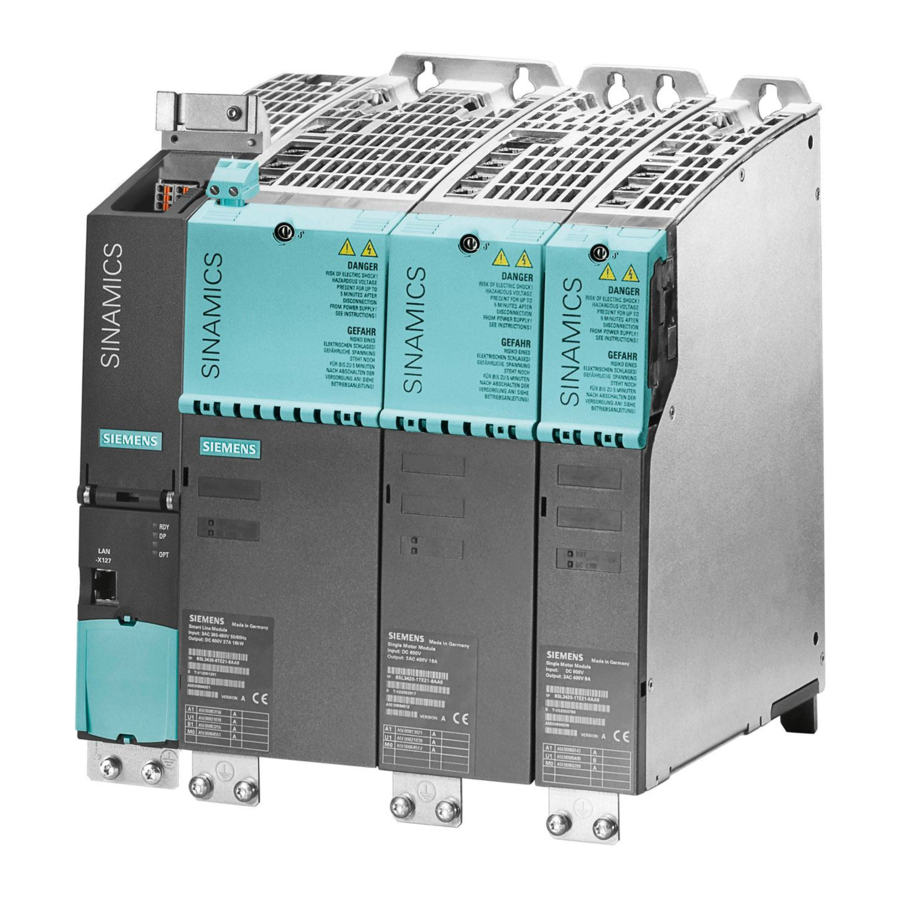
System Overview 1.5 SINAMICS S120 components SINAMICS S120 components This overview features the SINAMICS S120 components that are primarily used for multi- axis drive tasks. Figure 1-5 SINAMICS S120 component overview Equipment Manual for Control Units and Additional System Components... - Page 24 • Additional system components that enhance functionality and offer different interfaces for encoders and process signals. The SINAMICS S120 components were developed for installation in cabinets. They have the following features and characteristics: • Easy to handle, simple installation and wiring •...
-
Page 25: Power Sections
System Overview 1.6 Power sections Power sections Line modules Convert the three-phase supply into a DC voltage for the DC link. • Smart line modules The smart line modules generate a non-stabilized DC link voltage and are capable of regenerative feedback. •... -
Page 26: System Data
1.7 System data System data Technical specifications Unless explicitly specified otherwise, the following technical specifications are valid for all components of the SINAMICS S120 booksize drive system. Electrical data Line connection voltage 3 AC 380 V to 480 V ±10 % (-15 % <... - Page 27 System Overview 1.7 System data Climatic ambient conditions Storage • Class 1K3 to EN 60 721-3-1 Temperature -25 °C to +55 °C Class 2K4 to EN 60 721-3-3 Transportation • Temperature -40 °C to +70 °C Max. humidity 95 % at 40 °C Class 3K3 to EN 60 721-3-3 Operation •...
-
Page 29: Control Units
Control Units Introduction Description The control units of the SINAMICS S system are principally designed for use with several drives. The number of variable-speed drives depends on: • The required performance • The required special functions • The required operating mode (servo, vector, or V/f) The software and the parameters are stored on a plug-in CompactFlash Card. - Page 30 Control Units 2.1 Introduction Option Board (optional) With cover CompactFlash Card Figure 2-1 Overview of the control unit 320 (CU320) Note The control unit, the option board, and the CompactFlash Card must be ordered separately. If your application requires more than one control unit, the number can be increased accordingly.
- Page 31 Control Units 2.1 Introduction Controller PROFIBUS Active Active Single Single Single Single line line motor motor motor motor module module module module module module X103 X103 X102 X102 X101 X101 X100 X100 X202 X202 X202 X202 X202 X202 X201 X201 X201 X201 X201...
-
Page 32: Control Unit 320 (Cu320)
Control Units 2.2 Control Unit 320 (CU320) Control Unit 320 (CU320) 2.2.1 Description The CU320 is a central control module in which the closed-loop and open-loop functions are implemented for one or more active line and/or motor modules. The CU320 contains the following interfaces: Table 2-1 Overview of the CU320 interfaces Type... -
Page 33: Interface Description
Control Units 2.2 Control Unit 320 (CU320) 2.2.3 Interface description X103 X100 - X103 DRIVE-CliQ interfaces X100 Shield contact X122 Digital inputs/ outputs X132 X124 Electronics power supply Option slot PROFIBUS LEDs equipotential bonding terminal X126 PROFIBUS CompactFlash Card T0 - T2 Measuring sockets RESET button Rating plate... -
Page 34: Control Unit
Control Units 2.2 Control Unit 320 (CU320) ext. 24 V X100 X101 X102 X103 X124 + 24 V X126 PROFIBUS X122 Control Unit 320 DI 0 DI 1 DI 2 DI 3 DI/DO 8 DI/DO 9 1) DI/DO 10 1) 1) Fast inputs DI/DO 11 1) (must be shielded) - Page 35 Control Units 2.2 Control Unit 320 (CU320) DRIVE-CLiQ interface X100 - X103 Table 2-2 DRIVE-CLiQ interface X100-X103 Signal name Technical specifications Transmit data + Transmit data - Receive data + Reserved, do not use Reserved, do not use Receive data - Reserved, do not use Reserved, do not use + (24 V)
- Page 36 Control Units 2.2 Control Unit 320 (CU320) Digital inputs/outputs X122 Table 2-3 Terminal block X122 Terminal Name Technical specifications DI 0 Voltage: -3 V to 30 V Typical current consumption: 10 mA at 24 V DC DI 1 Isolation: The reference potential is terminal M1 DI 2 Level (incl.
- Page 37 Control Units 2.2 Control Unit 320 (CU320) Digital inputs/outputs X132 Table 2-4 Terminal block X132 Terminal Name Technical specifications DI 4 Voltage: -3 V to 30 V Typical current consumption: 10 mA at 24 V DC DI 5 Isolation: The reference potential is terminal M2 DI 6 Level (incl.
- Page 38 Control Units 2.2 Control Unit 320 (CU320) Electronics power supply X124 Table 2-5 Terminal block X124 Terminal Function Technical specifications Electronics power supply Voltage: 24 V DC (20.4 V - 28.8 V) Current consumption: Max. 0.8 A (without DRIVE-CLiQ or digital outputs) M (GND) Electronic ground Max.
- Page 39 The address switch is behind the blanking plate. The blanking plate is supplied. Setting the PROFIBUS address The following reference contains information about setting the PROFIBUS address: Reference: /IH1/ SINAMICS S120 Installation and Start-Up Manual Serial interface (RS232) X140 Reserved...
- Page 40 Control Units 2.2 Control Unit 320 (CU320) Measurement sockets T0, T1, and T2 Table 2-8 Measurement sockets T0, T1, and T2 Socket Function Technical specifications Measurement socket 0 Voltage: 0 V to 5 V Resolution: 8 bits Measurement socket 1 Load current: Max.
- Page 41 Control Units 2.2 Control Unit 320 (CU320) Slot for the CompactFlash Card Figure 2-5 CompactFlash Card slot Caution The CompactFlash Card may only be inserted as shown in the figure (arrow top right). The CompactFlash Card may only be inserted or removed when the control unit is disconnected from the power supply.
-
Page 42: Leds On The Control Unit
Control Units 2.2 Control Unit 320 (CU320) Description of the LEDs on the control unit Table 2-9 Description of the LEDs on the control unit Color State Description Electronics power supply outside permissible tolerance range. (READY) Continuous The component is ready for operation and cyclic DRIVE-CLiQ Green communication is taking place. - Page 43 2.2 Control Unit 320 (CU320) Cause and rectification of faults The following reference contains information about the cause and rectification of faults: Reference: /IH1/ SINAMICS S120, Installation and Start-Up Manual RESET button The RESET button is located behind the blanking plate.
-
Page 44: Dimension Drawing
Control Units 2.2 Control Unit 320 (CU320) 2.2.4 Dimension drawing Figure 2-6 Dimension drawing of the CU320 Equipment Manual for Control Units and Additional System Components 2-16 Equipment Manual, (GH1), 04.2004 Edition, 6SL3097-2AH00-0BP0... -
Page 45: Installation
Control Units 2.2 Control Unit 320 (CU320) 2.2.5 Installation Mounting the CU320 directly on a line module booksize Figure 2-7 Mounting the CU320 directly on a line module booksize Equipment Manual for Control Units and Additional System Components 2-17 Equipment Manual, (GH1), 04.2004 Edition, 6SL3097-2AH00-0BP0... - Page 46 Control Units 2.2 Control Unit 320 (CU320) Installing the CU320 directly on a mounting surface Torx (T10) M3 / 0.8 Nm 1. Loosen screws 3. Tighten screws 2. Push the lug up 4. Fix with screws (M6 / 6 Nm) Figure 2-8 Installing the CU320 directly on a mounting surface Equipment Manual for Control Units and Additional System Components...
- Page 47 Control Units 2.2 Control Unit 320 (CU320) Installing the CU320 on a mounting surface using spacer elements To provide the correct mounting depth for a booksize line-up with internal air cooling, you can use spacer elements. Spacer elements Figure 2-9 Installing the CU320 on a mounting surface using spacer elements Equipment Manual for Control Units and Additional System Components 2-19...
- Page 48 Control Units 2.2 Control Unit 320 (CU320) Removing/opening the protective cover of the CU320 Unlatch Swing open Remove Figure 2-10 Removing/opening the protective cover of the CU320 Equipment Manual for Control Units and Additional System Components 2-20 Equipment Manual, (GH1), 04.2004 Edition, 6SL3097-2AH00-0BP0...
-
Page 49: Technical Specifications
Control Units 2.2 Control Unit 320 (CU320) 2.2.6 Technical specifications Table 2-10 Technical specifications Unit Value Electronics power supply Voltage 24 DC (20.4 – 28.8) Current (without DRIVE-CLiQ or digital outputs) PE/ground connection On housing with M5/3Nm screw Weight Equipment Manual for Control Units and Additional System Components 2-21 Equipment Manual, (GH1), 04.2004 Edition, 6SL3097-2AH00-0BP0... -
Page 51: Additional System Components
Additional System Components Communication Board CAN (CBC10) 3.1.1 Description The CBC10 is a communication board for linking to CAN. 3.1.2 Safety information Caution The option board may only be inserted and removed when the control unit and option board are disconnected from the power supply. Caution The CBC10 must only be operated by qualified personnel. -
Page 52: Interface Description
Additional System Components 3.1 Communication Board CAN (CBC10) 3.1.3 Interface description CBC10 X451 CAN output X452 CAN input Weight: 0.1 kg Figure 3-1 Interface description of the CBC10 Equipment Manual for Control Units and Additional System Components Equipment Manual, (GH1), 04.2004 Edition, 6SL3097-2AH00-0BP0... - Page 53 Additional System Components 3.1 Communication Board CAN (CBC10) CAN bus interface X451 Table 3-1 CAN bus interface X451 Designation Technical specifications Reserved, do not use CAN_L CAN signal (dominant low) CAN_GND CAN ground Reserved, do not use CAN_SHLD Optional shield CAN ground CAN_H CAN signal...
- Page 54 Additional System Components 3.1 Communication Board CAN (CBC10) Figure 3-2 Switch S1/S2 Table 3-3 2-pin SMD DIL switch ID on the board Switch Function Switch position Default Bus terminating Inactive resistor Active Operation Ground-free with/without operation ground Operation with ground Equipment Manual for Control Units and Additional System Components Equipment Manual, (GH1), 04.2004 Edition, 6SL3097-2AH00-0BP0...
-
Page 55: Installation
Additional System Components 3.1 Communication Board CAN (CBC10) 3.1.4 Installation 1. Unscrew and remove the protective cover 2. Insert and secure Torx T10 the option board Fixing screws: M3 / 0.8 Nm Figure 3-3 Installation CBC10 3.1.5 Technical specifications Table 3-4 Technical specifications Communication Board CAN (CBC10) Max. -
Page 56: Option Board: Terminal Board 30 (Tb30)
Additional System Components 3.2 Option Board: Terminal Board 30 (TB30) Option Board: Terminal Board 30 (TB30) 3.2.1 Description The TB30 is a terminal expansion board for plugging in to the control unit. The TB30 contains the following terminals: Table 3-5 Interface overview of the TB30 Type Number... -
Page 57: Interface Description
Additional System Components 3.2 Option Board: Terminal Board 30 (TB30) 3.2.3 Interface description TB30 X424 Power supply for the digital inputs/outputs X481 Digital inputs/outputs X482 Analog inputs/outputs Figure 3-4 Interface description of the TB30 Equipment Manual for Control Units and Additional System Components Equipment Manual, (GH1), 04.2004 Edition, 6SL3097-2AH00-0BP0... - Page 58 Additional System Components 3.2 Option Board: Terminal Board 30 (TB30) ext. 24 V X424 + 24 V Terminal Board 30 X481 DI 0 DI 1 DI 2 DI 3 DO 0 DO 1 DO 2 DO 3 X482 AI 0+ ±10 V AI 0- AI 1+...
- Page 59 Additional System Components 3.2 Option Board: Terminal Board 30 (TB30) Power supply for digital inputs/outputs X424 Table 3-6 Terminal block X424 Terminal Function Technical specifications Power supply Voltage: 24 V DC (20.4 V – 28.8 V) Current consumption: Max. 4 A (per digital output max. Reserved, do not use 0.5 A) M (GND)
- Page 60 Additional System Components 3.2 Option Board: Terminal Board 30 (TB30) Digital inputs/outputs X481 Table 3-7 Terminal block X481 Terminal Name Technical specifications DI 0 Voltage: -3 V to 30 V Typical current consumption: 10 mA at 24 V DC DI 1 Ground reference: X424.
- Page 61 If the range is infringed, incorrect results may occur during analog/digital conversion. Handling analog inputs The following reference contains more information about analog inputs: Reference: /IH1/ SINAMICS S120, Installation and Start-Up Manual Equipment Manual for Control Units and Additional System Components 3-11 Equipment Manual, (GH1), 04.2004 Edition, 6SL3097-2AH00-0BP0...
-
Page 62: Installation
Additional System Components 3.2 Option Board: Terminal Board 30 (TB30) 3.2.4 Installation 1. Unscrew and remove the protective cover 2. Insert and secure Torx T10 the option board Fixing screws: M3 / 0.8 Nm Figure 3-6 Installation TB30 Equipment Manual for Control Units and Additional System Components 3-12 Equipment Manual, (GH1), 04.2004 Edition, 6SL3097-2AH00-0BP0... -
Page 63: Electrical Connection
Additional System Components 3.2 Option Board: Terminal Board 30 (TB30) 3.2.5 Electrical connection Shield connection of the TB30 on the control unit Shield contact on the control unit M3 / 0.8 Nm X482 Digital inputs/outputs Figure 3-7 Shield contact for the TB30 3.2.6 Technical specifications Table 3-9... -
Page 64: Terminal Module 31 (Tm31)
Additional System Components 3.3 Terminal Module 31 (TM31) Terminal Module 31 (TM31) 3.3.1 Description The TM31 is a terminal expansion board that can be attached to a DIN 50022 mounting rail. It can be used to increase the number of available digital inputs/outputs and analog inputs/outputs within a drive system. -
Page 65: Interface Description
Additional System Components 3.3 Terminal Module 31 (TM31) 3.3.3 Interface description X500 DRIVE-CliQ interfaces X501 X524 Electronics power supply X540 Auxiliary voltage for X520 digital inputs Digital inputs X530 X541 Voltage/current Digital measurement inputs/outputs X521 Analog inputs X522 X542 Analog outputs Relay outputs Shield connection PE conductor connection... - Page 66 Additional System Components 3.3 Terminal Module 31 (TM31) Figure 3-9 Example connection of TM31 Equipment Manual for Control Units and Additional System Components 3-16 Equipment Manual, (GH1), 04.2004 Edition, 6SL3097-2AH00-0BP0...
- Page 67 Additional System Components 3.3 Terminal Module 31 (TM31) X500 and X501 DRIVE-CLiQ interface Table 3-11 DRIVE-CLiQ interface X500 Signal name Technical specifications Transmit data + Transmit data - Receive data + Reserved, do not use Reserved, do not use Receive data - Reserved, do not use Reserved, do not use + (24 V)
- Page 68 Additional System Components 3.3 Terminal Module 31 (TM31) Digital inputs X520 Table 3-13 Screw terminal X520 Terminal Name Technical specifications DI 0 Voltage: -3 V to 30 V Typical current consumption: 10 mA at 24 V DC DI 1 Isolation: The reference potential DI 2 is terminal M1 DI 3...
- Page 69 Additional System Components 3.3 Terminal Module 31 (TM31) Digital inputs X530 Table 3-14 Screw terminal X530 Terminal Name Technical specifications DI 4 Voltage: -3 V to 30 V Typical current consumption: 10 mA at 24 V DC DI 5 Isolation: The reference potential is terminal M2 DI 6 Signal propagation times: DI 7...
- Page 70 Additional System Components 3.3 Terminal Module 31 (TM31) Auxiliary voltage for the digital inputs X540 Table 3-15 Screw terminal X540 Terminal Designation Technical specifications +24 V Voltage: +24 V DC Max. total load current: 150 mA +24 V +24 V +24 V +24 V +24 V...
- Page 71 Additional System Components 3.3 Terminal Module 31 (TM31) Analog inputs X521 Table 3-16 Terminal block X521 Terminal Name Technical specifications AI 0+ You can set the following input signals using parameters: AI 0- Voltage: -10 V to 10 V; R = 100 kΩ...
- Page 72 Additional System Components 3.3 Terminal Module 31 (TM31) Analog outputs/temperature sensor connection X522 Table 3-18 Terminal block X522 Terminal Name Technical specifications AO 0V+ You can set the following output signals using parameters: Voltage: -10 V to 10 V (max. 3 mA) AO 0- AO 0C+ Current 1: 4 mA to 20 mA (max.
- Page 73 Additional System Components 3.3 Terminal Module 31 (TM31) Bidirectional digital inputs/outputs X541 Table 3-19 Terminals for bidirectional digital inputs/outputs Terminal Name Technical specifications As input: Voltage: -3 V to 30 V DI/DO 8 Typical current consumption: 10 mA at 24 V DC DI/DO 9 Signal propagation times: DI/DO 10...
- Page 74 Additional System Components 3.3 Terminal Module 31 (TM31) Relay outputs X542 Table 3-20 Terminal block X524 Terminal Name Technical specifications DO 0.NC Contact type: Two-way contact max. load current: 8 A Max. switching voltage: 250 V , 30V max. switching DO 0.COM power at 250 V : 2000 VA (cosϕ...
-
Page 75: Dimension Drawing
Additional System Components 3.3 Terminal Module 31 (TM31) 3.3.4 Dimension drawing Figure 3-10 Dimension drawing of the TM31 Equipment Manual for Control Units and Additional System Components 3-25 Equipment Manual, (GH1), 04.2004 Edition, 6SL3097-2AH00-0BP0... -
Page 76: Installation
Additional System Components 3.3 Terminal Module 31 (TM31) 3.3.5 Installation Installation 1. Place the component on the DIN rail. 2. Snap the component on to the DIN rail. Make sure that the mounting slides at the rear latch into place. 3. -
Page 77: Electrical Connection
Additional System Components 3.3 Terminal Module 31 (TM31) 3.3.6 Electrical connection Shield contacts for the component are available from Weidmüller and Phönix Weidmüller Phönix Order no. Order no. KLBU CO 1 SK 8 Figure 3-12 Shield contacts Company internet addresses: Weidmüller: http://www.weidmueller.com Phönix: http://www.phoenixcontact.com Equipment Manual for Control Units and Additional System Components... -
Page 78: Technical Specifications
Additional System Components 3.3 Terminal Module 31 (TM31) Connector codes To ensure that identical connectors are assigned correctly on the TM31, the connecters are encoded as shown in the following diagram. Connector coding Figure 3-13 Connector codes of the TM31 3.3.7 Technical specifications Table 3-22... -
Page 79: Sensor System Connection
DRIVE-CLiQ. The sensor system can only be connected to SINAMICS S120 via DRIVE-CLiQ, whereby motor sensors are connected to the associated motor module, while external sensors are connected to the control unit. In conjunction with motor sensors, the motor temperature can also be evaluated using sensor modules. -
Page 80: Overview Of Sensor Modules
Sensor System Connection 4.2 Overview of sensor modules Overview of sensor modules 4.2.1 Description SMC10 SMC20 SMC30 Figure 4-1 Sensor modules Connectable sensor systems Table 4-1 Connectable sensor systems Measuring systems SMC10 SMC20 SMC30 Resolver Incremental encoder sin/cos (1Vpp) Absolute encoder EnDat Incremental encoder TTL/HTL Temperature evaluation Equipment Manual for Control Units and Additional System Components... -
Page 81: Sensor Connections
Sensor System Connection 4.3 Sensor Module Cabinet 10 (SMC10) 4.2.2 Sensor connections Sensor connection via SMC (Sensor Module Cabinet) Signal cable DRIVE- CLiQ Motor Module ϑ Power cable Motor Figure 4-2 Sensor connection Sensor Module Cabinet 10 (SMC10) 4.3.1 Description The cabinet-mounted sensor module 10 (SMC10) evaluates sensor signals and transmits the speed/position, rotor position and, if necessary, the motor temperature via DRIVE-CLiQ to the control unit. -
Page 82: Safety Information
Sensor System Connection 4.3 Sensor Module Cabinet 10 (SMC10) 4.3.2 Safety information Caution The 50 mm clearances above and below the components must be observed. Notice Only measuring systems in which the measuring system power supply is not grounded may be connected. -
Page 83: Interface Description
Sensor System Connection 4.3 Sensor Module Cabinet 10 (SMC10) 4.3.3 Interface description X500 DRIVE-CliQ interface X524 Electronics power supply X520 Sensor system connector PE conductor connection M4 / 1.8 Nm Figure 4-3 Interface description SMC10 Equipment Manual for Control Units and Additional System Components Equipment Manual, (GH1), 04.2004 Edition, 6SL3097-2AH00-0BP0... - Page 84 Sensor System Connection 4.3 Sensor Module Cabinet 10 (SMC10) DRIVE-CLiQ interface X500 Table 4-2 DRIVE-CLiQ interface X500 Signal name Technical specifications Transmit data + Transmit data - Receive data + Reserved, do not use Reserved, do not use Receive data - Reserved, do not use Reserved, do not use Reserved, do not use...
- Page 85 Sensor System Connection 4.3 Sensor Module Cabinet 10 (SMC10) X520 sensor system Table 4-3 Sensor interface X520 Signal name Technical specifications Reserved, do not use Reserved, do not use A (sin+) Incremental signal A A* (sin-) Inverted incremental signal A Ground Ground (for internal shield) B (cos+)
- Page 86 Sensor System Connection 4.3 Sensor Module Cabinet 10 (SMC10) Electronics power supply X524 Table 4-4 Terminal block X524 Terminal Function Technical specifications Electronics power supply Voltage: 24 V (20.4 V – 28.8 V) Current consumption: Max. 0.3 A Reserved, do not use Maximum current via jumper in connector: 20 A at 55 °C M (GND) Electronic ground...
-
Page 87: Dimension Drawing
Sensor System Connection 4.3 Sensor Module Cabinet 10 (SMC10) 4.3.4 Dimension drawing Figure 4-4 Dimension drawing of the SMC10 Equipment Manual for Control Units and Additional System Components Equipment Manual, (GH1), 04.2004 Edition, 6SL3097-2AH00-0BP0... -
Page 88: Installation
Sensor System Connection 4.3 Sensor Module Cabinet 10 (SMC10) 4.3.5 Installation Installation 1. Place the component on the DIN rail. 2. Snap the component on to the DIN rail. Make sure that the mounting slides at the rear latch into place. 3. -
Page 89: Technical Specifications
Sensor System Connection 4.4 Sensor Module Cabinet 20 (SMC20) 4.3.6 Technical specifications Table 4-6 Technical specifications Unit Value Electronics power supply Voltage 24 DC (20.4 – 28.8) Current Max. 0.3 PE/ground connection On housing with M4/1.8Nm screw Weight Sensor Module Cabinet 20 (SMC20) 4.4.1 Description The cabinet-mounted sensor module 20 (SMC20) evaluates sensor signals and transmits... -
Page 90: Interface Description
Sensor System Connection 4.4 Sensor Module Cabinet 20 (SMC20) 4.4.3 Interface description X500 DRIVE-CliQ interface X524 Electronics power supply Rating plate X520 Sensor system connector PE conductor connection M4 / 1.8 Nm Figure 4-6 Interface description of the SMC20 Equipment Manual for Control Units and Additional System Components 4-12 Equipment Manual, (GH1), 04.2004 Edition, 6SL3097-2AH00-0BP0... - Page 91 Sensor System Connection 4.4 Sensor Module Cabinet 20 (SMC20) DRIVE-CLiQ interface X500 Table 4-7 DRIVE-CLiQ interface X500 Signal name Technical specifications Transmit data + Transmit data - Receive data + Reserved, do not use Reserved, do not use Receive data - Reserved, do not use Reserved, do not use Reserved, do not use...
- Page 92 Sensor System Connection 4.4 Sensor Module Cabinet 20 (SMC20) X520 sensor system Table 4-8 Sensor interface X520 Signal name Technical specifications P encoder Sensor power supply M encoder Ground for sensor power supply Incremental signal A Inverted incremental signal A Ground Ground (for internal shield) Incremental signal B...
- Page 93 Sensor System Connection 4.4 Sensor Module Cabinet 20 (SMC20) Electronics power supply X524 Table 4-9 Terminal block X524 Terminal Function Technical specifications Electronics power supply Voltage: 24 V (20.4 V – 28.8 V) Current consumption: Max. 0.4 A Reserved, do not use Maximum current via jumper in M (GND) Electronic ground...
-
Page 94: Dimension Drawing
Sensor System Connection 4.4 Sensor Module Cabinet 20 (SMC20) 4.4.4 Dimension drawing Figure 4-7 Dimension drawing of the SMC20 Equipment Manual for Control Units and Additional System Components 4-16 Equipment Manual, (GH1), 04.2004 Edition, 6SL3097-2AH00-0BP0... -
Page 95: Installation
Sensor System Connection 4.4 Sensor Module Cabinet 20 (SMC20) 4.4.5 Installation Installation 1. Place the component on the DIN rail. 2. Snap the component on to the DIN rail. Make sure that the mounting slides at the rear latch into place. 3. -
Page 96: Technical Specifications
Sensor System Connection 4.5 Sensor Module Cabinet 30 (SMC30) 4.4.6 Technical specifications Table 4-11 Technical specifications Unit Value Electronics power supply Voltage 24 DC (20.4 – 28.8) Current Max. 0.4 PE/ground connection On housing with M4/1.8Nm screw Weight Sensor Module Cabinet 30 (SMC30) 4.5.1 Description The cabinet-mounted sensor module 30 (SMC30) evaluates sensor signals and transmits... - Page 97 Sensor System Connection 4.5 Sensor Module Cabinet 30 (SMC30) Table 4-12 Maximum signal cable lengths Sensor type Maximum signal cable length in m TTL* HTL unipolar HTL bipolar *For TTL sensor on X520 → Remote Sense → 100 m For TTL sensors with 5 V supply on X521/X531, the cable lengths (for 0.5 mm cable cross- sections) depend on the sensor current: 0.05...
-
Page 98: Safety Information
Sensor System Connection 4.5 Sensor Module Cabinet 30 (SMC30) 4.5.2 Safety information Danger The 50 mm clearances above and below the components must be observed. Notice Only one measuring system can be connected to each sensor module. Only measuring systems in which the measuring system power supply is not grounded may be connected. -
Page 99: Interface Description
Sensor System Connection 4.5 Sensor Module Cabinet 30 (SMC30) 4.5.3 Interface description X500 DRIVE-CliQ interface X524 Electronics power supply LEDs X520 TTL with open-circuit monitoring HTL, TTL without X521 open-circuit X531 monitoring PE conductor connection Shield connection M4 / 1.8 Nm Figure 4-10 Interface description SMC30 Equipment Manual for Control Units and Additional System Components... - Page 100 Sensor System Connection 4.5 Sensor Module Cabinet 30 (SMC30) DRIVE-CLiQ interface X500 Table 4-13 DRIVE-CLiQ interface X500 Signal name Technical specifications Transmit data + Transmit data - Receive data + Reserved, do not use Reserved, do not use Receive data - Reserved, do not use Reserved, do not use Reserved, do not use...
- Page 101 Sensor System Connection 4.5 Sensor Module Cabinet 30 (SMC30) Shield brackets for the SMC30 are available from: Weidmüller: http://www.weidmueller.com Phönix: http://www.phoenixcontact.com X521 sensor connection 2 HTL/TTL without open-circuit monitoring Table 4-15 Sensor connection X521 Designation Technical specifications Incremental signal A Inverted incremental signal A Incremental signal B Inverted incremental signal B...
- Page 102 Sensor System Connection 4.5 Sensor Module Cabinet 30 (SMC30) Electronics power supply X524 Table 4-17 Terminal block X524 Terminal Function Technical specifications Electronics power supply Voltage: 24 V (20.4 V – 28.8 V) Current consumption: Max. 0.6 A Reserved, do not use Max.
-
Page 103: Dimension Drawing
Sensor System Connection 4.5 Sensor Module Cabinet 30 (SMC30) 4.5.4 Dimension drawing Figure 4-11 Dimension drawing of the SMC30 Equipment Manual for Control Units and Additional System Components 4-25 Equipment Manual, (GH1), 04.2004 Edition, 6SL3097-2AH00-0BP0... -
Page 104: Installation
Sensor System Connection 4.5 Sensor Module Cabinet 30 (SMC30) 4.5.5 Installation Installation 1. Place the component on the DIN rail. 2. Snap the component on to the DIN rail. Make sure that the mounting slides at the rear latch into place. 3. -
Page 105: Electrical Connection
Sensor System Connection 4.5 Sensor Module Cabinet 30 (SMC30) 4.5.6 Electrical connection Shield contacts are only required if the system is connected to X521/X531. Shield contacts for the SMC30 from Weidmüller and Phönix Weidmüller Phönix Order no. Order no. KLBU CO 1 SK 8 Figure 4-13 Shield contacts for the SMC30... -
Page 107: A.1 Spring-Loaded Terminals/Screw Terminals
Appendix A Spring-loaded terminals/screw terminals Connectable conductor cross-sections of spring-loaded terminals Table A-1 Spring-loaded terminals Spring-loaded terminal type Connectable conductor cross- Flexible 0.14 mm to 1.5 mm sections With wire end ferrule, without plastic sleeve 0.25 mm to 1.5 mm With wire end ferrule, with plastic sleeve 0.25 mm to 0.5 mm... -
Page 108: A.1 Spring-Loaded Terminals/Screw Terminals
Appendix A A.1 Spring-loaded terminals/screw terminals Screw terminal type Connectable conductor cross- Flexible 0.2 mm to 4 mm sections With wire end ferrule, without plastic sleeve 0.25 mm to 4 mm With wire end ferrule, with plastic sleeve 0.25 mm to 4 mm Insulation stripping length 7 mm... -
Page 109: B.1 List Of Abbreviations
Appendix B List of abbreviations Table B-1 List of abbreviations Abbreviation English A... Alarm Alternating Current Analog Digital Converter Analog Input Analog Output Advanced Operator Panel ASCII American Standard Code for Information Interchange Operating condition BERO Tradename for a type of proximity switch Binector Input Berufsgenossenschaftliches Institut für... -
Page 110: B.1 List Of Abbreviations
Appendix B B.1 List of abbreviations Abbreviation English Central Processing Unit Cyclic Redundancy Check Constant Torque Control Unit Digital Analog Converter Direct Current Direct Current Negative Direct Current Positive Drive Data Set Digital Input DI/DO Bidirectional Digital Input/Output DRIVE-CLiQ Module Cabinet (Hub) Digital Output Drive Object DPRAM... - Page 111 Appendix B B.1 List of abbreviations Abbreviation English High Frequency High frequency reactor Ramp-function generator Human Machine Interface High Threshold Logic Hardware Input/Output Commissioning Identifier International Electrotechnical Commission IGBT Insulated Gate Bipolar Transistor In preparation: In preparation: this feature is currently not available Insulated three-phase supply network Jogging...
- Page 112 Appendix B B.1 List of abbreviations Abbreviation English NEMA National Electrical Manufacturers Association Zero mark Normally Open (contact) Original Equipment Manufacturer Optical Link Plug Option Module Interface p ... Adjustable parameter Power Module Data Set Protective Earth PELV Protective Extra Low Voltage Programming terminal Proportional Integral Programmable Logic Controller...
- Page 113 Appendix B B.1 List of abbreviations Abbreviation English Safe Brake Control Safe input signal Safe standstill Safety Integrated Safety Integrity Level SLVC Sensorless Vector Control Sensor Module Sensor Module Cabinet Setpoint Channel Programmable Logic Controller (PLC) PROFIBUS control word Terminal Board Totally Integrated Automation Terminal Module Grounded three-phase supply network...
-
Page 115: References
Order no.: E86060-K5151-A121-A3-7600 2. /D11/ SINAMICS G150 Drive Converter 75 – 560 kW Cabinet Units Order no.: E86060-K5511-A101-A1-7600 3. /D21.1/ SINAMICS S120 Vector Control Drive system Order no.: (in preparation) 4. /D21.2/ SINAMICS S120 Servo Control Drive system (incl. servo motors) Order no.: (in preparation) - Page 116 Appendix C C.1 References 3. /GH2/ SINAMICS S120 Equipment Manual for Booksize Power Sections Order no.: 6SL3097-2AC00-0BP0, edition: 01.2004 4. /GH3/ SINAMICS S120 Equipment Manual for Chassis Power Sections Order no.: 6SL3097-2AE00-0BP0, edition: 01.2004 5. /GS1/ SINAMICS S120 Getting Started Order no.: 6SL3097-2AG00-0BP0, edition: 01.2004...
- Page 117 SIMOTION Engineering System SCOUT Order no.: 6AU1 900-0AD30-0BA0, edition: 02.2003 6. DRIVE ES Basic V5.1 Function Description Engineering System for Drives from the Siemens A&D Product Range Order no.: 6SW1 700-0JA00-0BA0, edition: 08.2001 PROFIBUS documentation 1. /IKPI/ Catalog IK PI 2002/2003 Industrial Communication and Field Equipment Order no.: E86060-K6710-A101-B2-7600 (bound edition)
- Page 118 Function Description SINUMERIK Safety Integrated Order no.: 6FC5297-6AB80-0BP2, edition: 09.2003 5. /SIAH/ Safety Integrated The Safety Program for International Industry Application Manual, 4th edition, Siemens AG Automation and Drives Order no.: 6ZB5000-0AA01-0BA0, edition: 01.2003 6. /SICD/ Safety Integrated The Fully Integrated Safety System CD-ROM Order no.: E20001-D10-M103-X-7400-7600...
- Page 119 Index Control Unit 320 (CU320), 2-19 Terminal Board 30 (TB30), 3-12 Terminal Module 31 (TM31), 3-27, 4-12, 4-20, 4-30 Interface Descriptions Applications, 1-1 Cabinet-Mounted Sensor Module (SMC10), 4-6 Cabinet-Mounted Sensor Module 20 (SMC20), 4-14 Cabinet-Mounted Sensor Module 30 (SMC30), 4-25 Control Unit 320 (CU320), 2-8 Cabinet-Mounted Sensor Module 10 (SMC10), 4-3 Terminal Module 31 (TM31), 3-16...
- Page 120 Index Connector codes, 3-29 Totally Integrated Automation, 1-3 Versions, 1-2 Equipment Manual for Control Units and Additional System Components Index-2 Equipment Manual, (GH1), 04.2004 Edition, 6SL3097-2AH00-0BP0...
- Page 121 Overview of SINAMICS Documentation (01.2004) General Documentation / Catalogs MICRO- SINAMICS SINAMICS MASTER SINAMICS SINAMICS 410/420/ G110/ S150 S120 S120 430/440 G130/ G150 DA 51.2 D 21.2 D 21.3 D 21.1 Converter Servo Control Converter Vector Control Vector Control 0.12–250kW Drive System 0.12–3kW Blocksize Units Cabin Units...
- Page 123 Suggestions SIEMENS AG Corrections A&D MC BMS For Publication/Manual: P.O. Box 3180 SINAMICS S120 D-91050 Erlangen, Germany Equipment Manual (GH1) Phone: +49-(0)180-5050-222 (Hotline) Fax: +49-(0)9131-98-2176 (Documentation) Manufacturer/Service Documentation Email: motioncontrol.docu@erlf.siemens.de From Equipment Manual Name Order No.: 6SL3097-2AH00-0BP0 Company/Dept. Edition: 04.04...
- Page 126 Siemens AG Automation & Drives Motion Control Systems © Siemens AG, 2004 P.O. Box 3180, D-91050 Erlangen Subject to change without prior notice Germany Order No.: 6SL3097-2AH00-0BP0 Printed in Germany www.siemens.com/motioncontrol...
Need help?
Do you have a question about the SINAMICS S120 and is the answer not in the manual?
Questions and answers