Table of Contents
Advertisement
Advertisement
Table of Contents

Related Manuals for Thermal Arc ULTRA FLEX 350


Summary of Contents for Thermal Arc ULTRA FLEX 350
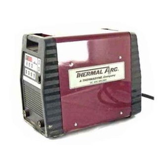
- Page 1 ® ULTRA FLEX For the Following Specs: • 500237A-1 Pulse OWNER’S MANUAL Number 430429-465 (Rev - 0) Issued February 28, 2000 IMPORTANT: Read these instructions before installing, operating, or servicing this system. THERMAL ARC INC., TROY, OHIO 45373-1085, U.S.A.
-
Page 2: Table Of Contents
430429-465 TABLE OF CONTENTS INTRODUCTION How To Use This Manual ........1-1 Equipment Identification . -
Page 3: Introduction
Cautions will be shown in bold type. Additional copies of this manual may be pur- chased by contacting Thermal Arc at the address NOTE offers helpful information concern- given above. Include the Owner’s Manual number ing certain operating procedures. Notes will and equipment identification numbers. - Page 4 430429-465 INTRODUCTION This page intentionally left blank. February 28, 2000...
-
Page 5: Arc Welding Safety Instructions And Warnings
ARC WELDING SAFETY INSTRUCTIONS AND WARNINGS Instruction 830001 ARC WELDING SAFETY INSTRUCTIONS AND WARNINGS ARC WELDING can be hazardous. PROTECT YOURSELF AND OTHERS FROM POSSIBLE SERIOUS INJURY OR DEATH. KEEP CHILDREN AWAY. PACEMAKER WEARERS KEEP AWAY UNTIL CONSULTING YOUR DOCTOR. DO NOT LOSE THESE INSTRUCTIONS. READ OPERATING/INSTRUC- TION MANUAL BEFORE INSTALLING, OPERATING OR SERVICING THIS EQUIPMENT. - Page 6 ARC WELDING SAFETY INSTRUCTIONS AND WARNINGS Instruction 830001 FUMES AND GASES can be hazardous 4. Read the Material Safety Data Sheets (MSDSs) and the manu- to your health. facturer’s instruction for metals, consumables, coatings, and cleaners. 5. Work in a confined space only if it is well ventilated, or while Welding produces fumes and gases.
- Page 7 ARC WELDING SAFETY INSTRUCTIONS AND WARNINGS Instruction 830001 ENGINE FUEL can cause fire or 2. Do not add fuel while smoking or if unit is near any sparks or open explosion. flames. 3. Allow engine to cool before fueling. If possible, check and add Engine fuel is highly flammable.
- Page 8 ARC WELDING SAFETY INSTRUCTIONS AND WARNINGS Instruction 830001 This page intentionally left blank. May 8, 1996...
- Page 9 PRECAUTIONS DE SECURITE EN SOUDAGE A L'ARC Instruction 830002 ′ PRECAUTIONS DE SECURITE EN SOUDAGE A L LE SOUDAGE A L′ARC EST DANGEREUX PROTEGEZ-VOUS, AINSI QUE LES AUTRES, CONTRE LES BLESSURES GRAVES POSSIBLES OU LA MORT. NE LAISSEZ PAS LES ENFANTS S’APPROCHER, NI LES PORTEURS DE STIMULATEUR CARDIAQUE (A MOINS QU’ILS N’AIENT CONSULTE UN MEDECIN).
- Page 10 PRECAUTIONS DE SECURITE EN SOUDAGE A L'ARC Instruction 830002 SELECTION DES NUANCES DE FILTRES OCULAIRES POUR LA PROTECTION DES YEUX EN COUPAGE ET SOUDAGE ( selon AWS A 8.2-73 ) Opération Dimension d’électrode ou Nuance de Epaisseur de métal ou de filtre Coupage ou soudage Intensité...
- Page 11 PRECAUTIONS DE SECURITE EN SOUDAGE A L'ARC Instruction 830002 LE SOUDAGE PEUT CAUSER UN IN- 4. Méfiez-vous des projections brulantes de soudage susceptibles CENDIE OU UNE EXPLOSION de pénétrer dans des aires adjacentes par de petites ouvertures ou fissures. L’arc produit des étincellies et des projections. Les 5.
- Page 12 PRECAUTIONS DE SECURITE EN SOUDAGE A L'ARC Instruction 830002 DES PIECES EN MOUVEMENT PEU- 3. Seules des personnes qualifiées doivent démonter des protec- VENT CAUSER DES BLESSURES. teurs ou des capots pour faire l’entretien ou le dépannage nécessaire. Des pièces en mouvement, tels des ventilateurs, des 4.
-
Page 13: Description Of Equipment
430429-465 DESCRIPTION OF EQUIPMENT DESCRIPTION OF EQUIPMENT General Welding. The pulse control includes 8 pre-pro- grammed factory pulse schedules with the ability to ® The Ultra Flex 350 is a DC inverter power source override any or all eight schedules using the op- that can be used for Constant Current (CC), Con- tional programming pendant (204180A-1). -
Page 14: Duty Cycle
430429-465 DESCRIPTION OF EQUIPMENT Duty Cycle ated at a given output without overheating the ma- ® chine. For example, the Ultra Flex has a rating of The duty cycle ratings for the Ultra Flex ® 350 power 35 volts and 375 amps with a duty cycle of 50%. source are listed in Tables 3-1 and 3-2. - Page 15 430429-465 DESCRIPTION OF EQUIPMENT Figure 3-2 Volt-Ampere Curves February 28, 2000...
-
Page 16: Description Of Controls And Features
430429-465 DESCRIPTION OF EQUIPMENT Description Of Controls And Pin A) Contactor Ckt. (+15 V) Pin B) Contactor Ckt. (A-B closure turns power Features source on) (See Figure 3-3) Pin C) Arc Volts Signal (+1 V =+10 Arc Volts) Pin D) Open 1 —... -
Page 17: Protection Features
430429-465 DESCRIPTION OF EQUIPMENT 8 — Voltage Select Switch: This switch is used e. Input Voltage Detection — If the input voltage to select the line voltage that the machine is con- is too high or too low (see machine specifications nected to. - Page 18 430429-465 DESCRIPTION OF EQUIPMENT 3 — FAULT LED INDICATOR: This indicator will to toggle between the “held” values of amps and be lit whenever the digital meter is displaying a fault volts. code, and the power source has shut itself off be- 10 —...
-
Page 19: Installation
430429-465 INSTALLATION INSTALLATION Location For best operating characteristics and longest unit life, take care in selecting an installation site. Avoid locations exposed to high humidity, dust, high am- bient temperature, or corrosive fumes. Moisture can condense on electrical components, causing corro- sion or shorting of circuits. -
Page 20: Use Of Engine-Generators For Input Power
430429-465 INSTALLATION For Single Phase Connection: The generator used for power should have good voltage and frequency regulation. If the generator’s 1. Connect the BLACK and WHITE wires to the output voltage or frequency (engine speed) varies AC power source. excessively with load, this may cause the protection circuits for high or low line voltage to shut down the 2. - Page 21 430429-465 INSTALLATION arc. When considering voltage drop, the entire loop (greater than 100 feet total length), try to avoid (electrode plus work lead) must be considered. coiling up the cables if possible. A damaged or frayed cable should not be used, and all connec- Refer to Table 4-2 as a basic guideline to the tions must be properly tightened.
- Page 22 430429-465 INSTALLATION This page intentionally left blank. February 28, 2000...
-
Page 23: Operation
430429-465 OPERATION OPERATION General use the UP and DOWN buttons to set the value. If the UP or DOWN button is held for more than two Read and understand the safety instructions at the seconds, the display will scroll at a more rapid rate. beginning of this manual prior to operating this During welding the A/V button is used to toggle machine. -
Page 24: Power Up Sequence
430429-465 OPERATION this light is on, there will be open circuit voltage on SMAW Operation the output terminals of the machine. (See Figure 5-1) ® The Ultra Flex 350 will “remember” all of the 1. Connect the welding leads to the power source control panel settings even after power has been with the correct polarity. -
Page 25: Lift Gtaw Operation
430429-465 OPERATION LIFT GTAW Operation 8. To energize the output of the machine, press the CONTACTOR button so that the light comes on. (See Figure 5-2) If a remote control is being used, the contactor can The purpose of Lift GTAW is to allow for striking be energized remotely using the switch on the re- the arc by momentarily touching the torch to the mote control. -
Page 26: Gtaw Operation
430429-465 OPERATION Electrode Welding Current, Amps Diameter DCEN DCEP Inches Using pure or thoriated tungsten electrodes .020 5-35 ——— .040 30-100 ——— 1/16 70-150 10-20 3/32 150-225 15-30 200-275 25-40 5/32 250-350 40-55 Table 5-1 Typical Current Ranges for Tungsten Electrodes nections to the arc starter with the power off. - Page 27 430429-465 OPERATION pressing the foot pedal. The high voltage will jump 8. To strike an arc, depress the foot pedal, or use the gap to the workpiece and the arc will follow. the torch switch. Open circuit voltage will now be present on the output of the power source.
-
Page 28: Gmaw/Fcaw Operation
430429-465 OPERATION GMAW/FCAW Operation source to condition the end of the wire for the next weld. The wire conditioning circuit will tend to leave ® The GMAW mode on the Ultra Flex 350 power the wire with a very small ball on the end of the wire, source provides a constant voltage output charac- thus making the next start easier. - Page 29 430429-465 OPERATION Figure 5-4 Pulse Waveforms (min): I (min) refers to a minimum back- For welding applications where none of the 8 ground current level. If the current falls below this schedules will give adequate results, any or all 8 minimum level, it becomes difficult to maintain a schedules can be changed by the operator to fit the stable arc.
-
Page 30: Optional Programming Pendant
430429-465 OPERATION Optional Programming Pendant 3. Turn AC power switch to the ON position. The initial power up sequence will be complete in ap- An optional programming pendant allows any or proximately three seconds. all eight of the factory pulse schedules to be over- 4. - Page 31 430429-465 OPERATION chine is powered up in either the single or three There are two separate safes, one for single phase mode. Any changes to one will not affect phase operation and one for three phase opera- the other. tion. These safes are independent of each other, and are accessed automatically when the ma- OPTION OPTION...
- Page 32 430429-465 OPERATION OPTION OPTION FACTORY DEFAULT DISPLAY NUMBER FORMAT 1 PHASE 3 PHASE 10.0 10.0 6XX.X MINIMUM SELECTABLE VOLTAGE. This voltage is the lowest value that the user is capable of setting in GMAW local welding mode. Voltages below this value can not be entered by the user in local mode.
- Page 33 SAFE. The acceptable range of values is between 0 and 999. NOTE: In the case that you change and forget the code, contact Thermal Arc for instructions on how to access the SAFE and retrieve/change the code. The following parameters are programmable in preceding table.
- Page 34 430429-465 OPERATION This page intentionally left blank. 5-12 February 28, 2000...
-
Page 35: Maintenance
430429-465 MAINTENANCE MAINTENANCE If this equipment does not operate properly, stop three months, or more often as necessary, wipe and work immediately and investigate the cause of the blow out all dirt from the machine’s interior, with air malfunction. Maintenance work must be performed pressure of not over 25 psi. - Page 36 430429-465 MAINTENANCE This page intentionally left blank. February 28, 2000...
-
Page 37: Troubleshooting
430429-465 TROUBLESHOOTING TROUBLESHOOTING lead’s conductor and should be crimped to the lead’s insulation. The mating surfaces of the con- W AR N IN G : D is con ne ct th e nection should be clean and free of oxidation or power source from the input debris. - Page 38 430429-465 TROUBLESHOOTING 5. Troubleshooting Hints. Are the power source’s accessory circuit breakers tripped? Carefully note all operating conditions and prob- lem symptoms for effective troubleshooting diagno- Are accessories in good condition and sis. During problem analysis, bear in mind that the properly set? Is the wire feed speed cor- total welding system includes not only the power rect? Does the wire feed smoothly? Is the...
-
Page 39: Fault Codes
430429-465 TROUBLESHOOTING Fault Codes voltage is ok and machine will not reset, service will be required. ® The Ultra Flex 350 power source has several “E015” — Over/under voltage of the AC line. This standard protection circuits designed to assure the fault code is caused by an input AC voltage that is reliability of the machine. - Page 40 430429-465 TROUBLESHOOTING This page intentionally left blank. February 28, 2000...
-
Page 41: Parts List
430429-465 PARTS LIST PARTS LIST to another part. The part descriptions may be Equipment Identification indented to show part relationships. All identification numbers as described in the In- To determine the part number, description, quan- troduction chapter must be furnished when ordering tity, or application of an item, simply locate the item parts or making inquiries. - Page 42 430429-465 PARTS LIST ® Figure 8-1 Ultra Flex Welder Assembly February 28, 2000...
- Page 43 430429-465 PARTS LIST Parts List for Figure 8-1 Item Part Description Number Assy ® 500237A-1 Welder - Ultra Flex (Pulse) 205189 . Wrapper 204036 . Label - Precautionary 205120A . Label - Programs . Deleted . Deleted 205149 . Brace - Endcaps 205141 .
- Page 44 430429-465 PARTS LIST Figure 8-2 February 28, 2000...
- Page 45 430429-465 PARTS LIST Parts List for Figure 8-2 Item Part Description Number Assy ® 500237A-1 Welder - Ultra Flex (Pulse) (Continued) Ref. 202258-6 . Suppressor - W/Lug Assy. 205005-1 . Rectifier - Power 204944 . Heat Sink 203205 . Diode - Ultra Fast Recovery 205115 .
- Page 46 430429-465 PARTS LIST This page intentionally left blank. February 28, 2000...
-
Page 50: Statement Of Warranty
, Inc., A Thermadyne Company, warrants that its products will be free of defects in workmanship or material. Should any failure to conform to this warranty appear within the time period applicable to the Thermal Arc products as stated below, Thermal Arc shall, upon notification thereof and substantiation that the product has been stored, installed, operated, and maintained in accordance with Thermal Arc’s specifications, instructions, recommendations and recognized standard industry practice,...
Need help?
Do you have a question about the ULTRA FLEX 350 and is the answer not in the manual?
Questions and answers