Table of Contents
Advertisement
Quick Links
Revision 0.1
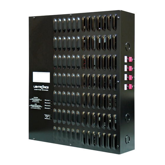
DESCRIPTION OF UNIT
The AT Series Dimmer is a unit specifically optimized for architecural applications. It can be supplied with up to
four 2400 Watt lighting circuits (channels) and be remotely controlled by a DMX lighting console. Some models
are provided with a fast acting 20 Amp magnetic circuit breaker for each channel. A table at the end of this
manual gives a description of the different model numbers. Additional models can be supplied for 220 VAC
The unit is intended for wall mounting. AT Series dimmers are for INDOOR USE ONLY.
POWER REQUIREMENTS
The AT Series dimmer requires a 120VAC hot power feed line for each lighting circuit (channel), a common
neutral, and an earth ground. Each of these feeds must powered by a circuit providing a minimum of 20 Amps
and supplies only one of the AT Series dimmer lighting circuits. The power feed for channel 1 also powers the
unit's internal electronic circuitry. The internal circuitry is protected by a replacable 1/2 Amp, 250 Volt, fast acting
fuse. The AT dimmer may be operated from either single phase or three phase power and may be switched
between these power types by the user.
INSTALLATION
CONTROL
TERMINAL STRIP
PROGRAMMING
CONTROLS
AND DISPLAY
www.lightronics.com
Lightronics Inc.
AT SERIES ARCHITECTURAL DIMMER
OWNERS MANUAL
AT-402 FRONT VIEW (Cover Removed)
CIRCUIT
BOARD
509 Central Drive Virginia Beach, VA 23454
1/2AMP FUSE
AND SPARE
1
2
LIGHTING
3
LOADS
4
1
120VAC
2
POWER IN
3
4
GROUNDS
NEUTRALS
Page 1 of 8
08/29/2003
1
2
3
CIRCUIT
BREAKERS
4
tel 757 486 3588
Advertisement
Table of Contents

Related Manuals for Lightronics AT SERIES


Summary of Contents for Lightronics AT SERIES
- Page 1 Each of these feeds must powered by a circuit providing a minimum of 20 Amps and supplies only one of the AT Series dimmer lighting circuits. The power feed for channel 1 also powers the unit's internal electronic circuitry.
- Page 2 LOAD CONNECTIONS The AT Series dimmer is intended for incandescent lamp loads. You can connect up to 2400 Watts of lighting to each channel. Connect lighting loads to the upper terminal strip positions as indicated by the label. The neutral bar and ground lug may be used for lighting loads.
- Page 3 INITIAL SET UP Set up of the AT Series dimmer is done using the 2 LED indicators and the 3 push buttons located at the bottom left of the low voltage section of the the circuit board inside of the unit. Use these controls to set the unit to operate correctly for the type of input power being used for the unit.
- Page 4 CIRCUIT BREAKERS Some models of AT Series dimmers use circuit breakers. If it does - there is a 20 Amp magnetic circuit breaker for each dimmer channel located on the right side of the unit. To operate a channel, the associated circuit breaker must be closed.
- Page 5 Page 5 of 8 AT SERIES ARCHITECTURAL DIMMER OWNERS MANUAL Revision 0.1 08/29/2003 PROGRAMMING THE UNIT: The LED's will alternate between the FUNCTION (channel/preset level and preset fade) and its VALUE (intensity and fade time). There are 2 digits and 3 buttons to control everything. Press the NEXT button to advance through each FUNCTION.
- Page 6 Page 6 of 8 AT SERIES ARCHITECTURAL DIMMER OWNERS MANUAL Revision 0.1 08/29/2003 TO SET THE INDIVIDUAL UP/DOWN FADE TIMES (or skip this section) These settings will over-ride the fade up/down settings in the previous section. SYMBOL FUNCTION VALUE Channel 1, Preset A - up fade time...
- Page 7 The cabinet should be opened only by a qualified electrician. The only user servicable part in the AT Series dimmer is the Type ABC, ½ Amp, 250 Volt, fast acting fuse. A spare fuse is provided with the unit. The fuse may be replaced ONLY with an identical fuse.
- Page 8 WARRANTY All Lightronics products are warranted for a period of TWO YEARS from the date of purchase against defects in materials and workmanship. This warranty is subject to the following restrictions and conditions: If service is required, you may be asked to provide proof of purchase from an authorized Lightronics dealer.
Need help?
Do you have a question about the AT SERIES and is the answer not in the manual?
Questions and answers