Table of Contents
Advertisement
Quick Links
PXI@STÃH6IV6GÃÃÃÃÃÃÃÃÃÃÃÃÃQhtrà ÂsÃ!
$6 /
',00(5
Revision 3.1
09/09/1999
Please take a moment to read this manual before operating the AS-40.
DHQPSU6IU)Ã
9@T8SDQUDPI
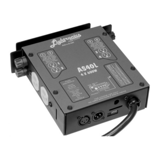
The AS-40 is a 4 channel, 600 Watts per channel portable lighting dimmer. The maximum load for the unit is 2400
Watts. The AS-40 is compatible with the industry standard 3 wire multiplex control signal protocol. The unit is
compact, very rugged, and simple to operate. There are no adjustments needed for pre-heat or trimming since the
unit uses autosync circuitry. The unit is protected from control cable shorts/miswiring by an internal device. Output
channels on the AS-40 may be assigned, in groups of 4, to channel numbers 1 through 64.
DITU6GG6UDPI
LOCATION: The AS-40 is designed to be mounted to a light truss or bar using a pipe clamp or similar secure
mounting intended for this purpose. A safety cable must be used in conjunction with the clamp to secure the unit in
the event of clamp failure. The AS-40 should be kept away from moisture and excessive heat. Please use common
sense.
CONTROL SIGNAL CONNECTIONS: The male three pin "XLR" connector on the end of the unit connects to your
lighting console. The female "XLR" connector is used to connect to other dimmers.
POWER CONNECTIONS: A dual blade, grounded, power input cable is provided at one end of the unit to connect to
a 120 volt AC, 20 Amp grounded service. The LED indicator located near the input power cable will indicate when
power is applied. The 4 power sockets ( 2 on each side of the unit) are the 4 output channels to be connected to the
lamps.
Lightronics Inc.
509 Central Drive, Virginia Beach, VA 23454
Tel: 757 486-3588
Advertisement
Table of Contents

Related Manuals for Lightronics AS-40


Summary of Contents for Lightronics AS-40
- Page 1 9@T8SDQUDPI The AS-40 is a 4 channel, 600 Watts per channel portable lighting dimmer. The maximum load for the unit is 2400 Watts. The AS-40 is compatible with the industry standard 3 wire multiplex control signal protocol. The unit is compact, very rugged, and simple to operate.
- Page 2 40 cover to select the proper switch settings. A "1" in the table indicates a switch in the UP position. The AS-40 may be switched into a “non-dim” or “relay” mode by a small slide switch located near the LED power indicator.
Need help?
Do you have a question about the AS-40 and is the answer not in the manual?
Questions and answers