
Related Manuals for Qvis Qvis DVR series


Summary of Contents for Qvis Qvis DVR series
- Page 1 4 - 8 - 16 Channel User’s Manual ® www.cctvireland.ie Lo-Call 1890 866 900 e-sales@cctvireland.ie...
- Page 2 ENHANCE YOUR DVR WITH OUR WIDE RANGE OF CAMERAS OUR PRODUCTS ARE FULLY TESTED TO WORK TOGETHER P400 CAMERAS VANDAL DOMES EYEBALL DOMES PTZ CAMERAS INTERNAL DOMES MINI CAMERAS DONT SETTLE FOR LESS, ALL OUR PRODUCTS CARRY LOGOS www.cctvireland.ie Lo-Call 1890 866 900 e-sales@cctvireland.ie...
-
Page 3: Table Of Contents
Directory 1 Welcome ..................5 2 Open-package check and cable connections ........6 Initial check ............6 Hard disk installation ............6 Front panel .................7 Rear panel ................9 Audio and video input and output connections ......10 2.5.1 Video input connections ..........10 2.5.2 Video output connections and options .......10 2.5.3 Audio signal input ............10 2.5.4 Audio signal output ............11... - Page 4 System ................34 4.4.1 General ................34 4.4.2 Encode .................35 4.4.3 Network ..............36 4.4.4 NetSevice ..............36 4.4.5 GUI Display ..............42 4.4.6 PTZ ................43 4.4.7 Tour ................43 4.4.8 Tour setup ..............44 Advanced ................44 4.5.1 HDD Manage ...............44 4.5.2 Account ...............45 4.5.3 Online user ..............47 4.5.4 TV adjustment ..............47 4.5.5 Auto maintain ..............47 4.5.6 Restore...
-
Page 5: Welcome
1. Welcome Thank you for purchasing our DVR! This manual is designed to be a reference tool for the installation and operation of your Qvis DVR series DVR system. You will find information about this Qvis DVRseries DVR's features and functions, as well as a detailed menu tree. Before you begin installation and operation please read the following safeguards... -
Page 6: Open-Package Check And Cable Connections
2 Initial check and cable connections 2.1 Initial check When you first receive your DVR, please check the following: 1. Please check whether there is any visible damage to the package appearance. The protective materials used for the package of the DVR can protect the DVR against most accidental damage during transportation. 2. Please open the box and get rid off the plastic protective materials. Check whether there is any visible damage to the DVR itself. -
Page 7: Front Panel
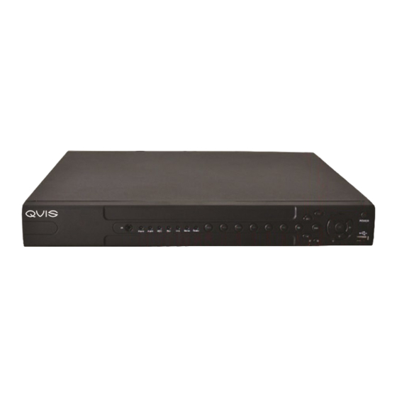
5). Connect SATA data wire 6). Connect the power wire 7). Put the top back on 8). Screw on the cover 2.3 Front panel (may vary on some models) (3) Alarm indicator light IR remoter receiver Power indicator light HDD indicator light Record indicator light (6) Network indicator light Status indicator lighter (8) - Page 8 Front panel function table Serial NO Mark Function Switch SHIFT Under the state of the user input,can completed switch Function function between numeric keys, character keys and other function keys Arrow Move the cursor Edit box, press the key you can increase or decrease the digital Optional drop-down menu, change the settings Monitor screen, enter the channel 1 or channel 4, single- screen monitor Enter to the text box, press the SHIFT key, press this key to enter the number 1 or 4 Pop-up menu or submenu, press the left and right arrow keys move the cursor Video playback state, press the left and right arrow keys to move the focus on the function keys Monitor screen, enter the channel 2 or channel 3 single- screen monitor Enter to the text box, press the SHIFT key, press the button,...
-
Page 9: Rear Panel
2.4 Rear panel Note: This is the interface for a 4 channel rear panel of a DVR. See Appendix 3 on page 57 for more details for specific models. (1) Video input (4) USB (7) VGA (2) Video output (5) Network (8) Power (3) Audio output (6) Audio input (9) Switch Installation sketch map www.cctvireland.ie Lo-Call 1890 866 900 e-sales@cctvireland.ie... -
Page 10: Audio And Video Input And Output Connections
2.5 Audio and video input and output connections 2.5.1 Video input connections The video input port is a BNC connector plug. The type of input signal is PAL/ NTSC BNC(1.0VP-P ,75Ω). The video signal must be of the correct standard and have a high signal to noise ratio, low aberration and low interference. The image must be clear and have natural color and brightness in the environment in which it is to operate. -
Page 11: Audio Signal Output
2.5.4 Audio signal output Commonly the output parameter of a DVR audio signal is greater than 200mv 1KΩ(BNC) which can connect a low impedance earphone and active sound box or other audio output equipments through a power amplifier. If the sound box and the tone arm can not be isolated, a howling phenomena is often experienced. Here are some methods to deal with this phenomena. 1). -
Page 12: Alarm Input Port Specifications
5. Alarm input type unlimited The DVR alarm output port is constant opening type. (1) alarm input (2) grounding (3) RS232 (4) alarm output (5) RS485 Parameter Meaning grounding (earth) C1, NO1 Alarm output interface(constant open type) T, R RS232 port A, B 485communication interface which is connected with the recording control equipments such as the decoder 2.6.1 Alarm input port specification... -
Page 13: Alarm Output Port Relay Perameters
2.6.3 Alarm output port relay parameters Type: JRC-27F Interface material Silver Rating Rating switch capacity 30VDC 2A, 125VAC 1A (resistance load) Maximal switch power 125VA 160W Maximal switch voltage 250VAC, 220VDC Maximal switch current isolation Homo-polarity interface 1000VAC 1minute Inhomo-polarity interface 1000VAC 1 minute Interface and winding 1000VAC 1 minute Surge voltage Homo-polarity 1500VAC (10×160us) Turn-on time 3ms max... -
Page 14: Basic Operation
3 Basic operation Note: The button in gray display indicates nonsupport. 3.1 Turn on Plug in and turn on the power supply switch. If the Power supply indicator light lights up then the video recorder has turned on. After startup you will hear a beep. The default setting of the video output is a multiple-window output mode. If the startup time is within a set video recording time, the timing video recording function will start up automatically. -
Page 15: Preview
Picture 3.1 System Login Password protection: If the password is entered continuously wrong for three times, the alarm will start. If the password is continuously wrong five times, the account will be locked. (Through a reboot or after half an hour, the account can be unlocked automatically). -
Page 16: Main Menu
Picture 3.2 Shortcut Menu 3.5.1 Main menu When you login, the system main menu is shown as below. Picture 3.3 Main Menu www.cctvireland.ie Lo-Call 1890 866 900 e-sales@cctvireland.ie... -
Page 17: Playback
3.5.2 Playback There are two methods for you to play the video files in the hard disk. 1). In the desktop shortcut menu. 2). Main menu>Record->Playback Note: The hard disk that saves the video files must be set as read-write or read- only state.(4.5.1) Picture 3.4 video playback 1). Listed files 2). File information 3). File searching 4). File backup 5). - Page 18 Detect: Detect the storage connected with the DVR such as hard disk or universal disk. Erasure: Choose the file to delete and click erasure to delete the file. Stop: Stop the backup. Backup: Click backup button and the dialog box is popped up. You can choose the backup file according to the type, channel and time. Picture 3.6 recording backup Remove: Clear the file information. Add: Show the file information satisfying the set file attributes. Start/Pause: Click the play button to start the backup and click the pause button to stop the backup. Cancel: During backup you can exit the page layout to carry out other functions. (File searching) Search the file according to the searching parameter. Picture 3.7 file searching File type: Set the searching file type. Channel: Set the searching channel. Start Time: Set the searching time scan.
-
Page 19: Record Mode
Button Function Button Function Play/pause Backward Stop Slow play Fast play Previous frame Next frame Previous file Next file Circulation Full screen Table 3.2 Playback control key Note: Frame by frame playback is only performed in the pause playback state. (Operation hint) Display the function of the cursor place. Special functions: Accurate playback: Input time (h/m/s) in the time column and then click play button. -
Page 20: Alarm Output
3.5.4 Alarm output • Please check current channel status: “o” means it is not in alarming status, “ ” means it is in alarming status. You can use desktop shortcut menu or click [main menu]> [alarm function]> [alarm output] to enter the alarm output interface. Picture 3.9 alarm output (Configuration) Alarm is on according to the configuration. (Manual) Click the all button and the according channel is alarming no matter the channel in any state. - Page 21 Speed: Set the PTZ rotation range. Default range: 1 ~ 8. Zoom: Click / button to adjust the zoom multiple of the camera. Focus: Click / button to adjust the focus of the camera . Iris: Click / button to adjust the iris of the camera. Direction control: Control the PTZ rotation. 8 directions control is supportive. (4 directions in Front panel is supported ) High speed PTZ: Full-screen shows channel image. Left mouse click to control the PTZ rotation and orientation. Left click mouse and then rotate the mouse to adjust the zoom multiple of the camera. Set: Enters the function operation menu. Page switch: Switchs between different pages. Special functions: 1).
- Page 22 Picture 3.12 PTZ Control 2: Cruise between Points A PTZ camera can be set to cruise between a series of preset points. This is called a cruise. To set the PTZ up to do this is as follows: 1). Cruise Between Points Settings A cruise line is a set up of multiple preset connected points, the setup procedure is as follows: Step 1: In Picture 3.10, use the Direction key to turn the PTZ to a designated location, click the settings button to enter Picture 3.13, Step 2: Click the Tour button, enter the tour number into the Patrol Number box if it isn't already showing and then click Add preset. The number of presets in the tour will show in the Preset box.
- Page 23 3: Scan The PTZ can also work on the preset scan line repeatedly. 1). Scan setup Step 1: In Picture 3.10, click the Setup button, which takes you to Picture 3.14; Step 2: Click the Pattern button and input a patrol value in the pattern value blank; Step 3: Click the begin button and enter Picture 3.10, here you can set the following items: Zoom, Focus, Aperture, Direction and so on. Click Set button to go back Picture 3.14; Step 4: Click the End button to complete the setup, Click the right button of the mouse to exit. Picture 3.14 Scan Setup 2).
-
Page 24: Color Setting
2). Boundary Scan Calls In Picture 3.10, click the Page Shift button to enter the PTZ control menu as shown in Picture 3.12. Please input the number of the scan in the value blank , then click the AutoScan button, the PTZ will begin to work on the scan line . Click the stop button to stop. 5: Rotating the Horizontal Click the Horizontally Rotating button and the PTZ will begin to rotate horizontally (relative to the original position of the camera). -
Page 25: Output Adjust
Picture 3.18 Color Setting 3.5.7 Output Adjust Adjust TV output area parameters. You can use the desktop shortcut menu or enter [main menu]> [management tools]> [Output adjust]. Picture 3.19 Output Adjust 3.5.8 Logout To logout, shut down the system or reboot the system. You can use the desktop shortcut menu or enter [main menu]. Picture 3.20 Logout/Reboot the system (Logout) Quit the menu. -
Page 26: Main Menu
4 Main menu 4.1 Main menu navigation Main menu Sub menu Function Record Config Set the recording configuration, recording type, recording time section Playback Set recording look-up, recording play, video file storage Backup Detect or format backup equipment, back the selective files Alarm Motion detection Set motion detect alarm channel, sensitivity, area, linkage parameters: defending time section, alarm output, screen hint, recording, PTZ, patrol Video blind Set camera mask alarm channel, sensitivity, linkage parameters: defending time section, alarm output, screen hint, recording, PTZ, patrol Video loss Set video loss alarm channel, linkage parameters: defending time section, alarm output, screen hint, recording, PTZ, patrol Alarm input Set the alarm input channel, equipment type, linkage parameters: defending time section, alarm output, screen hint, recording, PTZ, patrol Alarm output... -
Page 27: Record
Main menu Sub menu Function System Hard disk information Display hard disk capability and recording time information Code stream statistics Display code stream information Log information Clear all log information according to the log video and time Edition information Display edition information Shut down Logout or reboot 4.2 Record... -
Page 28: Snapshot Storeage
(Period) Set the time section for common recording, The recording will start only within the set range. (Record type) Set recording type: regular, detection or alarm. Regular: Perform regular recording in the set time section. The video file type is “R”. Detect: Trigger the “motion detect”, “camera mask” or “video loss” signal. When the above alarm is set as the opening recording, the “detection recording” state is on. The video file type is “M”. Alarm: This triggers the external alarm signal in the set time section. When the above alarm is set as the opening recording, the “detection recording” state is set to on. The video file type is “A”. Note: Refer to chapter 4.3 to set corresponding alarm function. 4.2.2 Snapshot Storage Setup snapshot parameters for different channels.At first time it's set for 24hours snapshot continuously, pls go to Main Menu->Record->Snapshot Storage for appropriate settings. Note:If normal snapshot storage,pls setup Snap at Main Menu->Advanced- >Snapshot(pls refer to chapter 4.5.1 HDD Manage) Picture 4.2 (Channel) Select the related channel to set,click "all" to set all channels. -
Page 29: Playback
4.2.3 Playback Refer to chapter 3.5.2. 4.2.4 Backup You can backup the video files to external storage through setup. Note: The storage must be installed before the file backup. If the backup is terminated, the files already backed up can be played back individually. Picture 4.3 Backup (Detect) Detects the storage connected with the DVR such as hard disk or universal disk. -
Page 30: Alarm
4.3 Alarm Function Alarm functions include: motion detect, video blind, video loss, alarm input and alarm output. 4.3.1 Motion Detect When the system detects a motion signal that reaches the set level of sensitivity, the motion detect alarm is switched on and the linkage function is turned on. Picture 4.4 Motion Detect (Channel) Choose the set motion detect channel. (Enable) means that the motion detect function is on. (Sensitivity) Choose in the six options according to the sensitivity. - Page 31 Picture 4.6 set the time section (Interval) Only one alarm signal is turned on even if there are several motion detection signals in the set interval. (Alarm output) Starts the external equipment of the linked alarm when the motion detect alarm is turned on. (Delay) Delay a few moments and stop when the alarm state is turned off. The range is 10~300 seconds.
-
Page 32: Video Blind
4.3.2 Video Blind When the video image is influenced by environmental factors such as excessive brightness or reaching the set sensitivy parameter, the camera mask function and the linkage function are turned on. Picture 4.9 Video Blind Set method: refer to chapter 4.3.1. Motion detect Note: "Advanced" button is the same as right-click. 4.3.3 Video Loss When the equipment can not obtain the channel video signal, the video loss alarm is turned on and the linkage function is turned on. Picture 4.10 Video loss Set method: refer to chapter 4.3.1. Motion detect Note: "Advanced" button is the same as rightclick. -
Page 33: Alarm Input
4.3.4 Alarm input When the system gets an external alarm signal, the alarm function is turned on. Picture 4.11 Alarm input Set method: refer to chapter 4.3.1. Motion detect Note:"Advanced" button is the same as rightclick. 4.3.5 Alarm output Refer to chapter 3.5.4. 4.3.4 Abnormal Analysing and inspecting current software and hardware of the device: When some abnormal events happen, the device will make a relative answer such as show message and buzzer. Picture 4.12 Abnormal (Event Type) Selecting the abnormity you want to inspect (Enable) Select it to make sure the abnormal function works... -
Page 34: System
4.4 System setup Set the system parameters such as General, Encode, NetWork, NetService, GUI Display, PTZ Config, RS232 and Tour Setup. 4.4.1 General Picture 4.13 General setup (System time) Set the system data and time. (Date format) Choose the data format: YMD, MDY, DMY. (Date Separator) Choose list separator of the data format. (Time Format) Choose time format: 24-hour or 12-hour. (Language) Arabic, Czech, English, Finnish, Greek, Indonesian, Italian, Japanese, Portuguese, Russian, Thai, T-Chinese, S-Chinese, Turkish, Brazilian, Bulgarian, Farsi, French, German, Hebrew, Hungarian, Polish, Romanian, Spanish, Swedish, Vietnamese (HDD full) Choose stop record: Stop recording when the hard disk is full Choose overwrite: Cover the earliest recording files and continue recording when the hard disk is full. (DVR No.) Only when the address button in the remote controller and the corresponding DVR number is matched, the remote operation is valid. -
Page 35: Encode
4.4.2 Encode setup Set the video/audio code parameters: video file, remote monitoring and so on. Set every independent channel’s coding parameter in the left part, and set the combine encode parameter in the right part. Note: Combine encode introduces video compression technique which combines and compresses multi-channel’s video to a special channel. Applying for multi- channel playback simultaneously, Dial-up multi-channel real-time monitor, mobile monitor and so on. Picture 4.16 Encode setup (Channel) Choose the channel number. -
Page 36: Network
4.4.3 Network setup Picture4.17 Network (Net Card) You can choose cable network card or wireless network card. (DHCP Enable) Obtain IP address automatically (not suggested) Note: DHCP server is preinstalled. (IP address) Set the IP address. Default: 192.168.1.10. (Subnet mask) Set the subnet mask code. Default: 255.255.255.0. (Gateway) Set the default gateway. Default: 192.168.1.1. (DNS setup) Domain Name Server. It translates the domain name into IP address. The IP address is offered by network provider. - Page 37 (PPPoE setup) Picture 4.19 PPPOE Input the user name and password that the ISP (Internet service provider) provides. After saving it reboot your system. Then the DVR will build a network connection based on PPPoE. The IP address will change into a dynamic IP address after the above operation is done.
- Page 38 (EMAIL setup) If the alarm is turned on or the alarm linkage photos are taken, the system can send an email of the alarm information and the photos to an appointed address. Picture 4.21 EMAIL SMTP server: Email server address. This could be an IP address or a domain name. A domain name can only be used if it has the correct DNS configuration. Port: Email server port number. SSL: Decide whether to use Secure Socket Layer protocol to login. User Name: Apply the email server user name. Password: Input the user password. Sender: Set the senders email address. Receiver: Send the email to the appointed receiver(s) when the alarm is turned on. You can set up to three receivers. Title: You can set this as you wish. (IP Filter setup) When choosing from the white list, only those IP addresses listed can connect to the DVR.
- Page 39 (DDNS) (dynamic domain name server). Local domain name: Insert the domain name registered by the DDNS. User name: Insert the user name. Password: Insert the password. When the DDNS is successfully configured and started, you can connect the domain name in the IE address column to visit. Note: The DNS setup must be configured correctly in the network setup. Picture 4.23 DDNS setup (FTP setup) FTP is available only when an alarm happens, or an alarm activates a record and takes a snapshot, it will then upload the related records and snapshot pictures to the FTP server.
- Page 40 (ARSP) Startup DDNS server to add devices and manage it in the DDNS server Type: choose "DNS" Enable: means it is chosen Sever IP: IP address of DDNS server Port: (Wireless Config) ADSL through 3G net card,use CMS to visit and config the device Picture 4.25 Wireless Config (Enable) Choose Enable to make all settings available (Type) Dial type,default AUTO (Wireless AP) 3G access point (Dial Number) 3G Dial Number...
- Page 41 (Enable) Select this to make sure the abnormal function is working (Port) This is the port to enable mobile monitoring. You will need to make a router map of it if you want to view everything by mobile (UPNP) UPNP protocol can set auto port forwarding on the router, make sure UPNP is running on the router before useing it. Picture 4.27 (Enable) Choose Enable to make sure all UPNP settings available (HTTP) Route will automatically distribute HTTP port for the device,when IE...
-
Page 42: Gui Display
4.4.5 GUI Display Configure the video output parameters including the front output mode and code output mode. Front output: In the local preview mode and includes: channel title, time display, record status, alarm status, bitrate info, transparency and region cover. Code output:In the network surveillance and video file mode include: channel title, time display, record status, alarm status, bitrate info, transparency and region cover. Picture 4.28 GUI Display (Channel Title) Click the channel name modify button and enter the channel name menu. -
Page 43: Ptz
4.4.6 PTZ setup Picture 4.29 PTZ setup (Channel) Choose the dome camera input channel. (Protocol) Choose the corresponding dome protocol. (PELCOD as an example) (Address) Set as the corresponding dome address. Default: 1. (Note: The address must be consistent with the dome address.) (Baud rate) Choose the corresponding dome baud rate length. You can control the PTZ and vidicon. Default: 115200. (Data bits) Include 5-8 options. Default: 8. -
Page 44: Tour Setup
4.4.8 Tour setup Set the patrol display. means that the tour mode is turned on. You can choose the single window, four windows, nine windows, sixteen windows patrol display or single display. Picture 4.31 tour setup (Interval) Set the patrol switch interval. The set range is 5-120 seconds. Note: / means turn off/on the patrol. 4.5 Advanced 4.5.1 HDD Manage Configure and manage the hard disk. The menu displays current hard disk information: hard disk number, input port, type, status and overall capability. The operation include: setup the write-read disk, read-only disk, redundant disk, hard disk format, resume default. Choose the hard disk and click the right function... -
Page 45: Account
4.5.2 Account Manage the user purview. Note: 1. T he maximum character length is 8 bytes for the following user and user team name. A blank ahead of or behind a character string is invalid. A middle blank in the character string is valid. Legal characters include: letters, numbers, underline, subtraction sign, dot. 2. There is no limit to the number of users or user groups. You can add or delete a user group according to the user definition. - Page 46 (Add user) To add a user to the team and set the user authority. Enter the menu interface and input the user name and password. Choose the team and choose whether cover using is to be activated. Cover using means that the account can be used by multiple users at the same time.
-
Page 47: Online User
4.5.3 Online User Look up the network user information in the local DVR. You can choose the network user and cut the connection. Then the user is locked until next boot- strap. Picture 4.38 Online User 4.5.4 TV adjust Refer to chapter 3.5.7. 4.5.5 Auto Maintain The user can set the auto reboot time and auto file deleting time limit. -
Page 48: Upgrade
4.5.7 Upgrade Picture 4.41 Upgrade (Upgrade) choose USB interface. (Upgrade file) choose the file which needs upgraded. 4.5.8 Device Info Provide device interface info like audio in,alarm in/out to be conveniently used for user. Picture 4.42 Device Info. 4.6 Info 4.6.1 HDD info Display the hard disk state: hard disk type, overall capability, residual capability, the recording time and so on. Picture 4.43 HDD Info www.cctvireland.ie Lo-Call 1890 866 900 e-sales@cctvireland.ie... -
Page 49: Bps
Clue: means that the hard disk is normal. X means that the hard disk is not working. means that there is no hard disk. If the user needs to change the damaged hard disk then you must shut down the DVR and remove all the damaged hard disks before installing a new one. -
Page 50: Version
4.6.4 Version Display the basic information such as hardware information, software edition, issue data and so on. Picture 4.46 Version 4.7 Shut down system Refer to chapter 3.5.8. www.cctvireland.ie Lo-Call 1890 866 900 e-sales@cctvireland.ie... -
Page 51: Faq And Maintenance
5 FAQ and maintenance 5.1 FAQ If your problems is not listed, please contact your local installer for service. The DVR can not boot up normally. Possible reasons are as followed: The power supply is not correct. Switch power supply line is not in good connection. Switch power supply is damaged. The program updating is wrong. The hard disk is damaged or the hard disk lines are broken. - Page 52 Real-time image problems such as the image color or the brightness distortion. Possible reasons are as followed: 1 When using the BNC output, the option between the N mode or PAL mode is wrong and the image becomes black and white. The DVR is not matched the monitor impedance. The video transmission distance is too far or the loss of the video trans mission line is too large.
- Page 53 11). The DVR can not control the PTZ. Possible reasons are as followed: There is something wrong with the frontal PTZ. 2 The setting, connection or the installation of the PTZ decoder is not correct. The connections are not correct. The PTZ setting of the DVR is not correct. The protocols of the PTZ decoder and the DVR are not matched. The address of the PTZ decoder and the DVR are not matched.
- Page 54 15). Network connection is not stable. Possible reasons are as followed: Network is not stable. 2 IP address is conflicted. 3 MAC address is conflicted. The net card of the DVR is bad. 16). There is something wrong with the USB backup or writing a CD. Possible reasons are as followed: The rewritable machine and the hard disk are shared the same data lines.
-
Page 55: Maintenance
21). The storage time is not enough. Possible reasons are as followed: Front vidicon quality is bad. The lens is too dirty. The vidicon is in back lighting installation. The hard disk capability is not enough. The hard disk is damaged. 22). -
Page 56: Appendix 1.Remote Controller Operation
Appendix 1.Remote controller operation (6)(1) (5) (8)(7) Serial Number Name Function Multi-window button Same function as Multi-window button in the front panel Numeric button Code input/number input/channel switch (Esc) Same function as (Esc) button in the front panel Direction button Same function as direction button in the front panel Record control Control the record Record mode... -
Page 57: Appendix 3.Technique Parameters
Appendix 3.Technique parameters Type 16ch System Main processor High performance embedded microprocessor Operation system Embedded LINUX operation system System resource synchronous multi-channel recording, synchronous multi- channel sub-code stream, synchronous multi-channel playback, synchronous network operation Interface Operation interface 16 bit true color graphical menu interface, mouse operation supportive display 1/4image display 1/4/8/9 image 1/4/8/9/16 image display display Video Video standard PAL 625line,50 f/s;NTSC 525 line,60 f/s Surveillance image PAL, D1(704x576);NTSC, D1(704x480) -
Page 58: Www.cctvireland.ie Lo-Call 1890 866 900 E-Sales@Cctvireland.ie
Type 16ch Other Power supply 12V/2A external power supply Power consumption <15W (without hard disk) Working 0ºC~+55ºC temperature Working humidity 10%–90% Air pressure 86kpa–106kpa Size 350*290*45MM Weight 3.5kg (without hard disk) Installation Desktop www.cctvireland.ie Lo-Call 1890 866 900 e-sales@cctvireland.ie...
Need help?
Do you have a question about the Qvis DVR series and is the answer not in the manual?
Questions and answers
setting up hand held remote control to match appolo dvr
To set up the handheld remote control for the Qvis DVR series, ensure that the address button on the remote controller matches the corresponding DVR number. Only when these match will the remote operation be valid.
This answer is automatically generated