
Related Manuals for Black Horse Model JU87-STUKA


Summary of Contents for Black Horse Model JU87-STUKA
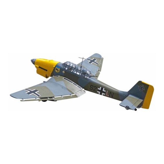
- Page 1 Instruction Manual book SPECIFICATION Wingspan : 1,920 mm 75.59 in. Length 1,560 mm 61.42 in. Weight 5 kg 11.00Lbs. Radio 06 channels. Servo 09 servos. Engine 4 stroke. Made in Vietnam.
-
Page 2: Parts List
Instruction Manual Item code: BH80 This instruction manual is designed to help you build a great flying aeroplane. Please read this manual thoroughly before starting assembly of your JU87-STUKA. Use the parts listing below to identify all parts. WARNING. Please be aware that this aeroplane is not a toy and if assembled or used incorrectly it is capable of causing injury to people or property. -
Page 3: Safety Precaution
JU87-STUKA - INSTRUCTION MANUAL Item code: BH80. SAFETY PRECAUTION. + This is not a toy + Be sure that no other flyers are using your radio frequency. + Do not smoke near fuel + Store fuel in a cool, dry place, away from children and pets. -
Page 4: Installing The Aileron Linkages
JU87-STUKA - Instruction Manual Item code: BH80 Aileron control horn Repeat the procedure for the other wing half. 2.INSTALLING THE AILERON LINKAGES. Installing the aileron linkages as pictures below. M2 lock nut 95mm C/A glue. - Page 5 JU87-STUKA - INSTRUCTION MANUAL Item code: BH80. 3) Using the thread as a guide and using masking tape, tape the servo lead to the end of the thread: carefully pull the thread out. C/A glue When you have pulled the servo lead out, re- move the masking tape and the servo lead from the thread.
- Page 6 JU87-STUKA - Instruction Manual Item code: BH80 2.INSTALLING THE FLAP CONTROL HORN. Remove covering Remove covering Bottom side Nilon control clasp 3mm x 40mm. M3 lock nut. Thread Electric wire. Secure Flap control horn. Bottom side...
- Page 7 JU87-STUKA - INSTRUCTION MANUAL Item code: BH80. 2.INSTALLING THE FLAP2 CONTROL HORN. 3. INSTALLING THE FLAP1 Repeat the procedure for the other flap1. LINKAGES. Installing the flap1 linkages as pictures below. M2 lock nut 125mm C/A glue Remove covering Nilon control clasp C/A glue 3mm x 40mm.
- Page 8 JU87-STUKA - Instruction Manual Item code: BH80 Flap1 Flap2 Repeat the procedure for the other wing half. 3. INSTALLING THE FLAP2 LINKAGES. MAIN GEAR INSTALATION. Installing the flap2 linkages as pictures below. PARTS REQUIRED M2 lock nut 135mm 3 x 15mm...
- Page 9 JU87-STUKA - INSTRUCTION MANUAL Item code: BH80. 3 x 15mm Drill 2mm hole Drill 2mm hole Secure...
- Page 10 JU87-STUKA - Instruction Manual Item code: BH80 Secure Secure...
- Page 11 JU87-STUKA - INSTRUCTION MANUAL Item code: BH80. Secure C/A glue Secure C/A glue...
-
Page 12: Installing The Engine Mount
JU87-STUKA - Instruction Manual Item code: BH80 INSTALLING THE ENGINE MOUNT. See pictures below: 4x 30mm C/A glue 4x 30mm... -
Page 13: Installing The Stopper Assembly
JU87-STUKA - INSTRUCTION MANUAL Item code: BH80. 2. Using a modeling knife, cut one length of Drill a hole silicon fuel line (the length of silicon fuel line is 4mm diameter calculated by how the weighted clunk should rest about 8mm away from the rear of the tank and move freely inside the tank). -
Page 14: Installing The Engine
JU87-STUKA - Instruction Manual Item code: BH80 6. When satisfied with the alignment of the stopper assembly tighten the 3mm x 20mm machine screw until the rubber stopper ex- pands and seals the tank opening. Do not over tighten the assembly as this could cause the tank to split. - Page 15 JU87-STUKA - INSTRUCTION MANUAL Item code: BH80. Secure Mark point Drill a hole 4mm diameter. Pushrod wire COWLING. 1. Slide the fiberglass cowl over the en- gine and line up the back edge of the cowl with the marks you made on the fuselage.
-
Page 16: Installing The Spinner
JU87-STUKA - Instruction Manual Item code: BH80 2. While keeping the back edge of the cowl flush with the marks, align the front of the cowl with the crankshaft of the engine. The front of the cowl should be positioned so the crankshaft is in nearly the middle of the cowl opening. - Page 17 JU87-STUKA - INSTRUCTION MANUAL Item code: BH80. Connector. Servo arm. 3 x 12mm After installing the adjustable metal con- nector apply a small drop of thin C/A to the bottom nut. This will prevent the con- nector from loosening during flight.
-
Page 18: Elevator Installation
JU87-STUKA - Instruction Manual Item code: BH80 C/A glue ELEVATOR INSTALLATION. SERVO INSTALLATION. 1. Install the rubber grommets and brass collets into the elevator servo. Test fit the servo C/A glue into the servo tray. 2. Mount the servo to the tray using the mounting screws provided with your radio sys- tem. - Page 19 JU87-STUKA - INSTRUCTION MANUAL Item code: BH80. C/A glue 3. Mark the shape of the vertical on the left and right sides onto the horizontal stabilizer using a felt-tip pen C/A glue Mark line. 4. Remove the stabilizer. Using the lines 1.
- Page 20 JU87-STUKA - Instruction Manual Item code: BH80 HORIZONTAL STABILIZER STRUTS. Epoxy glue. 6. After the epoxy has fully cured, remove the masking tape or T-pins used to hold the C/A glue stabilizer in place and carefully inspect the glue joints. Use more epoxy to fill in any...
- Page 21 JU87-STUKA - INSTRUCTION MANUAL Item code: BH80. C/A glue C/A glue ELEVATOR AND RUDDER PUSHROD INSTALLATION. Elevator and rudder pushrod install as same as the way of aileron pushrod. Elevator control horn. Remove covering.
- Page 22 JU87-STUKA - Instruction Manual Item code: BH80 ELEVATOR AND RUDDER PUSHROD INSTALLATION. Secure Elevator and rudder pushrod install as same as the way of aileron pushrod. M2 lock nut. Elevator pushrod Secure Elevator Elevator pushrod pushrod Bend and cut. Elevator pushrod...
-
Page 23: Vertical Installation
JU87-STUKA - INSTRUCTION MANUAL Item code: BH80. Throttle pushrod. C/A glue VERTICAL INSTALLATION. Rudder servo install as same as method of elevator servo. See picture below: C/A glue 1) Using a modeling knife, remove the C/A glue covering from the top of the fuselage and the... - Page 24 JU87-STUKA - Instruction Manual Item code: BH80 3. Mark the shape of the vertical on the left and right side on the rudder using a felt-tip pen. Hingle slot Mark line Epoxy glue 4. Now, remove the rudder and using a...
-
Page 25: Rudder Control Horn Installa- Tion
JU87-STUKA - INSTRUCTION MANUAL Item code: BH80. C/A glue 6) When you are sure that everything is a aligned correctly, mix up a generous amount of 30 minute epoxy. Apply a thin layer to the slot in the mounting platform and to the verti- cal stabilizer mounting area. -
Page 26: Mounting The Tail Wheel Bracket
JU87-STUKA - Instruction Manual Item code: BH80 Elevator Elevator pushrod pushrod Rudder Control horn. MOUNTING THE TAIL WHEEL 2 x 35mm. BRACKET. M2 lock nut. 3x12mm 1. Set the tail wheel assembly in place on the plywood plate. The pivot point of the... - Page 27 JU87-STUKA - INSTRUCTION MANUAL Item code: BH80. C/A glue Elevator Elevator pushrod pushrod Rudder Rudder pushrod. pushrod.
-
Page 28: Installing The Switch
JU87-STUKA - Instruction Manual Item code: BH80 INSTALLING THE RECEIVER AND BATTERY. 1. Plug the servo leads and the switch lead into the receiver. You may want to plug an aileron extension into the receiver to make plugging in the aileron servo lead easier when you are installing the wing . -
Page 29: Wing Attachment
JU87-STUKA - INSTRUCTION MANUAL Item code: BH80. Top side Drill a hole 3mm diameter 4 x 30mm Top side Secure WING ATTACHMENT. Locate the aluminium wing dihedral brace. *** Test fit the aluminium tube dihedral brace into each wing haft. The brace should slide in easily. - Page 30 JU87-STUKA - Instruction Manual Item code: BH80 Wingbolt Secure Drill a hole 3mm diameter...
- Page 31 JU87-STUKA - INSTRUCTION MANUAL Item code: BH80. C/A glue C/A glue...
- Page 32 JU87-STUKA - Instruction Manual Item code: BH80 C/A glue C/A glue C/A glue C/A glue C/A glue...
-
Page 33: Control Throws
JU87-STUKA - INSTRUCTION MANUAL Item code: BH80. With the wing attached to the fuselage, all parts of the model installed ( ready to fly), and empty fuel tanks, hold the model at the marked balance point with the stabilizer level. -
Page 34: Pre-Flight Check
JU87-STUKA - Instruction Manual Item code: BH80 Aileron control Flap control PRE-FLIGHT CHECK. 1) Completely charge your transmitter and receiver batteries before your first day of fly- ing. 2) Check every bolt and every glue joint in your plane to ensure that everything is tight and well bonded.
Need help?
Do you have a question about the JU87-STUKA and is the answer not in the manual?
Questions and answers