Table of Contents
Advertisement
Installation, Operation and Maintenance
Type ES45T
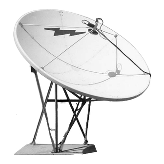
4.5-Meter ESA
Andrew Corporation
10500 West 153rd Street
Orland Park, IL U.S.A. 60462
4.5-Meter Earth Station Antenna
Telephone: 708-349-3300
FAX (U.S.A.): 1-800-349-5444
Internet: http://www.andrew.com
Customer Service, 24 hours: U.S.A. • Canada • Mexico: 1-800-255-1479
U.K.: 0800 250055 • Republic of Ireland: 1 800 535358
Other Europe: +44 1592 782612
Bulletin OM45T
Revision F
15 August, 2005
Copyright © 2005 by Andrew Corporation
Advertisement
Table of Contents

Related Manuals for Andrew ES45T


Summary of Contents for Andrew ES45T
- Page 1 Orland Park, IL U.S.A. 60462 Customer Service, 24 hours: U.S.A. • Canada • Mexico: 1-800-255-1479 U.K.: 0800 250055 • Republic of Ireland: 1 800 535358 Other Europe: +44 1592 782612 Bulletin OM45T Revision F 15 August, 2005 Copyright © 2005 by Andrew Corporation...
-
Page 2: Table Of Contents
ES45T-R Reflector ........ -
Page 3: Introduction
Andrew provides a complete line of available options, including field-installable electrical anti-icing heaters, pressurization equipment and interconnecting HELIAX cables and waveguide. An optional hoisting kit, which precludes the use of a crane, is available from Andrew and can be utilized as an installation tool for multiple installation purposes. Introduction... -
Page 4: Proprietary Data
Proprietary Data The technical data contained herein is proprietary to Andrew Corporation. It is intended for use in installation, operation, and maintenance of Andrew equipment. This data shall not be disclosed or duplicated in whole or in part without express written consent of Andrew Corporation. -
Page 5: How To Use This
Describes the controls, functions, and general operating procedures required for proper operation of the 4.5-Meter Earth Station Antenna • Maintenance Describes preventative maintenance procedures that are required to maintain proper functional operation of your new Andrew Earth Station Antenna. How to Use This Manual... -
Page 6: Getting Started Overview
125 mph winds in any operational position in moderate coastal/industrial areas. Severe conditions require additional protection. Should it be expected that winds will exceed 125 mph, it is recommended that Andrew antennae be steered to specific azimuth and elevation orientations to minimize wind forces upon the structure and thereby increase the probability of survival. -
Page 7: Recommended Tools
Additional warnings will be displayed throughout this manual for your awareness. These warnings can be identified in warning boxes as shown in the following sample. Andrew disclaims any liability or responsibility for the results of improper or unsafe installation, operation or maintenance practices. -
Page 8: Parts Verification
Tag or identify the defective equipment, noting the defect or circumstances. Also, be sure to write the RM number on the outside of the carton. It would be helpful to refer- ence the Andrew sales order and purchase order number, as well as the date the equip- ment was received. -
Page 9: Installation Sequence Checklist
Throughout the checklist certain part num- bers will be used. Those part numbers describe the antenna currently being installed. The ES45T-R is a receive-only 4.5-Meter Earth Satellite Antenna with a tripod mount. The ES45T-T is a transmit/ receive 4.5-Meter ESA with a tripod mount. -
Page 10: Tripod Ground Mount Assembly
Tripod Ground Mount Assembly ES45T-T Main Reflector Assembly ES45T-T Back Structure Assembly ES45T Reflector- to-Mount Assembly (With Crane) Feed Installation Waveguide/Flex Section Assembly Subreflector Installation Feed Installation Mount azimuth axis support and rear anchor pads Connect support angles Attach support and elevation pivot assembly to support angles... -
Page 11: Installation Procedures
Installation Procedures Overview Foundation Preparation This section provides installation procedures for the 4.5-Meter Andrew Earth Station Antenna. The installation procedures include instructions on the following antenna com- ponents. • Mount • Reflector • Back Structure • Reflector To Mount Assembly •... -
Page 12: A-325 Tensioning
A-325 Tensioning During the installation process there are several references to the A-325 hardware ten- sioning procedure. The A-325 hardware must be properly tensioned to avoid slippage between bolted surfaces under high loads. Slippage can cause the corresponding assembly to move, causing antenna misalignment. When designated, the A-325 hard- ware should be tightened according to the following tensioning procedure. -
Page 13: Tripod Mount
Tripod Mount The three-point mount in an elevation-over-azimuth configuration optimized for geosta- tionary satellite applications. The mount enables standard elevation ranges from 2°-62°, and 33°-90° with high-look strut configuration. Azimuth range is ±82°. Fine adjustment is provided in both azimuth and elevation. An example of the assembled tripod mount is provided in Figure 2. - Page 14 Step 2 Loosely connect support angles (P/N 49624) with spacers (P/N 46560-2) to azimuth axis support and rear anchor pads as shown in figure 5. • Use A-325 ½ x 1-½ in. bolts and nuts for connections. (see page 12) •...
- Page 15 Step 3 Lay out support and elevation pivot assembly (P/N 49635) and support angles (P/N 49623) as shown in Figure 6. Step 4 Loosely bolt support and elevation pivot assembly (P/N 49635) and support angles (P/N 49623) to connection plates as shown in Figure 7. •...
- Page 16 Step 5 Loosely attach support angles (P/N 49622) to the upper azimuth axis joint (P/N 300748) and the connection plates (part of P/N 49635)as shown in Figure 8. • Use A-325 ½ x 1-½ in. bolts, flatwashers and nuts. (see page 12) •...
- Page 17 Step 7 Tightly knot 40 ft. rope to azimuth axis joint (P/N 300748) for hoisting to azimuth axis support (P/N 49634). Step 8 Station one installer on a ladder to hoist support assembly as at least one other installer walks the assembly into the upright position as shown in Figure 10. Step 9 Loosely fasten lower azimuth axis joint (P/N 300746) and upper azimuth axis joint (P/N 300748) to azimuth axis support (P/N 49634) as demonstrated in Figure 11.
- Page 18 Step 10 Use a carpenter’s level to level support assembly as indicated in Figure 12. Loosen U- bolts to move support assembly up or down as needed to achieve level surface. Step 11 Tighten anchor bolts on rear pads and azimuth axis support base plate down using A- 325 procedure.
- Page 19 Step 13 Determine required length of elevation strut to nearest degree increment of desired ele- vation setting as specified in the Elevation and Azimuth Adjustments Section. Adjust coarse setting by extending secondary and, if necessary, tertiary sections to length. Install eight ½ in. set screws and securely tighten as pictured in Figure 15. CAUTION: Do not extend secondary or tertiary struts into red warning areas.
- Page 20 Step 14 Loosely attach azimuth strut end bracket (P/N 49767) to universal block (P/N 49705) as shown in Figure 16. • Use ¾ x 1-¼ in. bolts, flatwashers and lockwashers Step 15 Loosely attach block to appropriate rear pad as based upon calculations in Appendix F to determine the mounting configuration of the azimuth strut shown in Figures 16 and •...
- Page 21 Step 16 Connect U-bracket (P/N 49704) to appropriate connection plate. • Use A-325 ½ x 1-½ in. bolts, flatwashers and nuts. (see page 12) Step 17 Determine required length of azimuth strut to nearest degree increment of desired azimuth setting as specified in the Elevation and Azimuth Adjustments Section. Adjust azimuth setting by withdrawing secondary strut to achieve necessary length.
-
Page 22: Es45T-R Reflector
ES45T-R Reflector Assembly ES45T-R The ES45T-R-1 reflector is composed of six precision-formed panels designed for accu- Reflector racy and strength and ensure reliable surface contour which provides exceptional oper- ating characteristics in C- or Ku-frequency band. Step 1 Reflector should be assembled on a clear, flat area in front of the foundation pad. Clear debris from area and place plastic sheeting from packing crate as shown in Figure 22. - Page 23 ES45T-R Reflector Assembly Note: All six reflector segments are identified individually by a two letter designation (A- B, D-E, etc). Locate the markings on the reflector segments in order to assemble the reflector in the proper sequence. See Figure 21.
- Page 24 ES45T-R Reflector Assembly Step 4 Raise segments and hold while loosely attaching mounting ring hub (P/N 49965) to con- vex side of center opening. • Use ¼-20 capscrews, lockwashers and nuts • Insert capscrews from concave side of reflector segments...
- Page 25 ES45T-R Reflector Assembly Step 6 Loosely attach segment A-F to mounting ring hub, diameter setting bands and segment A-B using joining plates (P/N 49425) along reflector panel seam as pictured in Figure 24. • Place spacers (P/N 200215) between first and third segments •...
- Page 26 Step 8 Loosely attach segment E-F to mounting ring hub, diameter setting bands and segments A-F and D-E with joining plates (P/N 49425) along reflector panel seams E-E and F-F. Loosely attach joining plates (P/N 49693) on rim seams E-E and F-F as illustrated in Figure 26.
- Page 27 ES45T-R Reflector Assembly Step 10 Loosely attach reflector segment B-C to mounting ring hub and diameter setting bands. Use joining plates (P/N 49425) along B-B panel seam and joining plate (P/N 49693) on B-B rim seam. Step 11 Before last panel, lift reflector and return temporary supports to initial measuring posi- tion.
-
Page 28: Reflector Leveling Procedure
ES45T-R Reflector Assembly Step 12 Install last reflector panel (C-D) by loosely attaching to diameter setting bands and mounting ring hub. Loosely attach panel seam hardware as installer inside moves reflector segment to enable segment union. Loosely attach retaining bar (P/N 49997) to mounting ring hub (P/N 202429). Loosely Step 13 attach center plate (P/N 49964-2) to concave side of reflector. - Page 29 The differences between the highest location and a lower location will be the amount of shim material required to place between the reflector and the temporary support. ES45T-R Reflector Assembly Reflector Turnback Outside Edge...
-
Page 30: Feed Strut Assembly
Secure feed struts together after attachment to feed strut brackets as shown in Figure 32 You have now completed the assembly of the ES45T-R-1 or the ES45TDR reflector. The next step in the installation is the assembly of the back structure, which follows in the next section. -
Page 31: Back Structure
ES45T-R Reflector Assembly ES45T-R-1 The back structure assembly attaches to the rear of the reflector. The back structure Back Structure provides stability for the reflector and maintains the parabolic accuracy of the dish. An example of the assembled back structure is presented in Figure 33. - Page 32 ES45T-R Reflector Assembly Step 1 Refer to back structure Figure 34 for positioning and orientation details. • Apply stick wax (P/N 200852) to A-325 bolt threads before installation to reduce fric- tion. (see page 12) Note: Do not attempt to tighten A-325 hardware prior to tensioning sequence in assem-...
- Page 33 Step 2 Loosely attach tee plates (P/N 202447) to points B, F and D on convex side of reflector as shown in Figure 35. • Use A-325 ½ x 1-¼ in. bolts, flatwashers and nuts. (see page 12). • Insert bolts from concave side of reflector Step 3 Loosely attach plates (P/N 49427) to points A, C and E on convex side of reflector.
- Page 34 Step 4 Loosely attach support angles (P/N 49436) to three tee plates (P/N 202447) as shown in Figure 37. • Use A-325 ½ x 1-¼ in. bolts, flatwashers and nuts. (see page 12) • Install bolts from concave side of reflector •...
- Page 35 Step 6 Loosely attach support angles (P/N 49438) from plates A and C to angle (P/N 49436) from tee plate B with pivot bracket (P/N 300745). Step 7 Loosely connect support angles (P/N 49438) from plates E and C to angle (P/N 49436) from tee plate D to elevation axis bracket (P/N 300749) as shown in Figure 39.
-
Page 36: Reflector To Mount Assembly (With Crane)
Step 2 This reflector can be installed on the mount manually or by using a crane. However, Andrew recommends that this procedure be performed using a crane. The following steps provide the procedure for installing the reflector to the mount using a crane. - Page 37 Step 3 Crane should place reflector so that pivot brackets align with support and elevation pivot assembly as shown in Figure 42. Step 4 Attach pivot brackets to support and elevation pivot assembly with U-bolts (P/N 9956- 65), ½ in. lockwashers and ½-13 hex nuts as shown in Figures 43 and 44. Figure 42 Figure 43 Installation Procedures...
- Page 38 Figure 46 You have now completed the attachment of the reflector to the tripod ground mount assembly. If assembling a ES45T-R antenna, proceed to the Elevation and Azimuth Adjustments section for instructions on aiming your antenna at its desired satellite.
-
Page 39: Reflector To Mount Assembly (With Hoist Kit)
Loosely attach supports (P/N 49061) to corresponding tabs on support assemblies (P/N 49071 and 49072) using appropriate hardware (P/N 45980-1). • ES45T-R Reflector Assembly Angles should be installed edge down with flat of angles facing upward. Use supplied U-bolts with 1/2 inch (13 mm) lockwashers and nuts. - Page 40 ES45T-R Reflector Assembly Step 7 Loosely attach support (P/N 49060) and remaining ends of supports (P/N 49061) to cor- responding pick-up assemblies (P/N 49064) using appropriate hardware (P/N 45980-1). Securely tighten all mounting hardware. • Ensure entire hoist assembly is centered on support and elevation pivot assembly...
- Page 41 ES45T-R Reflector Assembly Step 11 Remove small portion of foam padding from reflector packing crate and install under bottom portion of reflector assembly to prevent reflector damage during hoisting proce- dure. Position man at bottom of reflector/backstructure to guide assembly during hoist- ing procedure.
- Page 42 Continue with feed system and corresponding LNA installation. You have now completed the attachment of the reflector to the tripod ground mount assembly. If installing an ES45T-R antenna, advance to the Elevation and Azimuth Adjustments section for instructions on pointing your antenna to its satellite.
-
Page 43: Elevation And Azimuth Adjustments
Elevation and Azimuth Adjustments Step 1 Proper antenna pointing requires specific coarse and fine elevation and azimuth strut length adjustments which can be determined using the graphs provided in Appendix F. Adjustable azimuth and elevation struts are initially set in coarse setting as near as pos- sible to pre-determined lengths. - Page 44 ES45T-R Reflector Assembly Step 8 Fine Adjustment. Attach fine adjustment assembly between adjacent elevation strut sections as shown in Figure 50 using appropriate brackets, U-bolts, brass hex nuts, flat- washers and threaded rod. Securely tighten all adjustment assembly hardware. Note: Adjustment assembly may also be attached in alternate position shown depend- ing on required elevation angle.
-
Page 45: Feed Support Assembly
Feed Support By now, you can see that your installation of the 4.5-Meter Earth Station Antenna is Assembly almost complete. The feed system is the last phase of the base installation described in this manual. Note: All antenna options (such as feeds, shields, anti-icing, etc.) possess installation instructions within the individual kits contained in the shipment. -
Page 46: Es45T-T Reflector
ES45T-T Reflector Assembly ES45T-T-1 The ES45T-T-1 reflector is composed of six precision-formed panels designed for accu- Reflector rate strength, and ensures a reliable surface contour that provides exceptional operating characteristics in C-, X- or Ku-frequency bands. Step 1 Reflector should be assembled on a clear, flat area in front of the foundation pad. Clear debris from area and place plastic sheeting from packing crate as shown in Figure 56. - Page 47 ES45T-T Reflector Assembly Note: All six reflector segments are identified individually by a two letter designation (A- B, D-E, etc). Locate the markings on the reflector segments in order to assemble the reflector in the proper sequence. See Figure 55.
- Page 48 ES45T-T Reflector Assembly Step 5 Loosely attach reflector segments A-B and D-E to diameter setting bands (P/N 49612) with edge joining plates (P/N 49424) and capscrew hardware as indicated in Figure 57. Reflector Segments Capscrew Hardware Side View Step 6 Loosely attach segment A-F to mounting ring hub, diameter setting bands, and segment A-B using edge joining plates (P/N 49424).
- Page 49 ES45T-T Reflector Assembly Step 7 Loosely attach joining plate (P/N 49693) along A-A seam inside reflector rim as shown in Figure 58. Capscrew Hardware 49693 Joining Plate Reflector Segments Step 8 Loosely attach segment E-F to mounting ring hub, diameter setting bands, and seg- ments A-F and D-E with joining plates (P/N 49424) on panel seams E-E and F-F.
- Page 50 Step 9 Station an installer inside reflector to finger-tighten seam hardware and attach final pan- els as shown in Figure 59. Step 10 Loosely attach reflector segment B-C to mounting ring hub and diameter setting bands. Use edge joining plate (P/N 49424) on B-B panel seam and joining plate (P/N 49693) on B-B rim seam.
-
Page 51: Reflector Leveling Procedure
Temporary supports should be large enough to adequately support the reflector and strong enough to easily support reflector weight without compressing. ES45T-T Reflector Assembly Insert capscrews from concave side - firmly push bolts through holes until bolt head is Refer to... - Page 52 ES45T-T Reflector Assembly Step 2 Position theodolite, transit or laser level about 10 feet [3m] from outside perimeter of reflector (see Figure 62). Line of Sight (0.0° Elevation) Theodolite, Transit or Laser Level Step 3 Level theodolite/transit/laser level. If using theodolite, position view scope at 0.0 degrees elevation, lock down elevation adjustment.
-
Page 53: Reflector Center Plate Assembly
Step 1 Install center plate (P/N 49964-2) over reflector center opening and retaining bar (P/N 49997) behind reflector center opening as shown using supplied capscrew hardware as shown in Figure 64. ES45T-T Reflector Assembly Reflector 202429 Mounting Ring 49997 Retaining Bar 1/4 x 1-1/2”... -
Page 54: Feed Strut Assembly
Secure feed struts together at center after attachment to feed strut brackets You have now completed the assembly of the ES45T-T-1 reflector. The next step in the installation is the assembly of the back structure, which begins in the next section. -
Page 55: Back Structure
ES45T-T Reflector Assembly ES45T-T-1 The back structure assembly attached to the rear of the reflector. The back structure Back Structure provides stability for the reflector and maintains the parabolic accuracy of the dish. Before assembling the back structure, verify that the appropriate parts are present. The following steps provide the procedure for the back structure assembly. - Page 56 Step 2 Loosely attach tee plates (P/N 202447) and corresponding rib connecting plates (P/N 202444) to points B, C, D, E, and F. • Use A-325 ½ x 1-¼ in. bolts, flatwashers and nuts. (see page 12) • Insert bolts from concave side of reflector CAUTION: Do not install A-325 ½...
-
Page 57: Reflector To Mount Assembly (With Crane)
This reflector can be installed on the mount manually or by using a crane. However, Mount Assembly Andrew recommends that this procedure be performed using a crane. (With Crane) The following steps provide the procedure for installing the reflector to the mount using a crane. - Page 58 Step 3 Crane should place reflector so that pivot brackets align with support and elevation pivot assembly as shown in Figure 68. Step 4 Attach pivot brackets to support and elevation pivot assembly with U-bolts (P/N 9956- 65), ½ in. lockwashers and ½-13 hex nuts as shown in Figures 69 and 70. Figure 68 Figure 69 Installation Procedures...
- Page 59 ES45T-T Reflector Assembly Figure 70 Step 5 Attach remaining end of elevation strut to elevation axis bracket of main triangle assem- bly as shown in Figures 71 and 72. • Use ¾ x 4-½ in. bolt, lockwasher and nut You have now completed the attachment of the reflector to the tripod ground mount assembly.
-
Page 60: Reflector To Mount Assembly (With Hoist Kit)
Loosely attach support (P/N 49060) and remaining ends of supports (P/N 49061) to cor- responding pick-up assemblies (P/N 49064) using appropriate hardware (P/N 45980-1). Securely tighten all mounting hardware. • Ensure entire hoist assembly is centered on support and elevation pivot assembly (P/N 49635) ES45T-T Reflector Assembly Figure 73 Installation Procedures... - Page 61 ES45T-T Reflector Assembly Step 8 Securely attach winch assembly (P/N 39532) to lower portion of azimuth axis support (P/N 49634) using supplied U-bolts, lockwashers and nuts as shown in Figure 74. • Keep winch cable aligned with sheaves Step 9 Begin releasing winch cable.
- Page 62 ES45T-T Reflector Assembly Step 12 Hoist reflector/backstructure assembly to vertical position until upper joints of main trian- gle assembly contact pipe and straddle two locator bars on support and elevation assembly (P/N 49635) as shown in Figure 75. Step 13 Install two U-bolts at each pivot bracket of main triangle assembly.
-
Page 63: Elevation And Azimuth Adjustments
Step 15 Set fine elevation and azimuth strut positions based on the procedure performed in the Elevation and Azimuth Adjustment section. • If fine alignment is not performed at this time, continue the assembly procedure at Step 16. Step 16 Securely tighten U-bolts and elevation strut mounting hardware. - Page 64 ES45T-T Reflector Assembly Step 6 Determine required length of azimuth strut to nearest degree increment of desired azimuth setting. Adjust coarse azimuth setting by withdrawing secondary strut section from primary strut to achieve desired strut length. Install four 1/2 inch (13 mm) set screws in holes provided and securely tighten.
-
Page 65: Feed Support/Strut Assembly
Step 10 Set fine elevation and azimuth strut positions by loosening strut set screws and selected out fine adjustment hex nut. Turn corresponding inner hex nut in appropriate direction until required strut length is achieved. Securely tighten strut set screws and correspond- ing outer hex nut. -
Page 66: Polarization Adjustment
Polarization Adjustment Step 1 Connect receive LNA output to spectrum analyzer and fine adjust elevation and azimuth strut lengths to achieve maximum signal strength from desired satellite. Step 2 Loosen four 3/8 x ½ in. set screws in feed support until feed assembly is free to rotate and adjust feed for maximum receive signal strength on desire polarization. -
Page 67: Medium Modular Mount
Medium Modular Refer to bulletin 237151C, for Installation Instructions. Mount... -
Page 68: Operation Overview
There are several procedures that may be used to properly acquire the satellite. Andrew recommends that a spectrum analyzer be used. The following procedures provide explanations as to how to use the spectrum analyzer. - Page 69 While viewing the spectrum analyzer screen, a pure noise signal as shown in Figure 1 will probably be observed. Additionally, some transponder signals may be observed above the noise signal as shown in Figure 2. The following steps provide the procedure for acquiring a satellite. Step 1 Manually move the antenna in the azimuth (scanning back-and-forth) to achieve the maximum (greatest amplitude) transponder signals.
- Page 70 The maximum azimuth excursion from the original setting should not exceed ±1.5° or the antenna may begin to access a different satellite. Step 2 With the antenna positioned in azimuth such that the transponder signals are maxi- mized, follow the same procedure manually moving the antenna in elevation (scanning up-and-down) to further maximize the transponder signals.
- Page 71 Step 6 Move the antenna in elevation while observing the spectrum analyzer screen. If the sig- nal amplitude increases, decreases and then increases again but to a lesser value, the antenna is moving in the wrong direction; reverse the direction of the antenna move- ment.
-
Page 72: Manual Actuator Assembly Removal
Manual Actuator After you have successfully acquired the satellite and all adjustments have been made, Assembly Removal the manual actuator should be removed. The following steps provide the procedure for the proper removal of the manual actuator assembly. Step 1 Remove the manual actuator assembly by first removing the hardware securing the actuator to the base angle. -
Page 73: Preventive Maintenance
Preventive Maintenance Overview General Cleaning Electrical Parts This section contains periodic preventative maintenance instructions for the 4.5-Meter Earth Station Antenna. Included in this section are inspection and preventative mainte- nance procedures including cleaning and lubrication, painting and an operational volt- age/current checkout procedure deemed within the capabilities of the average station technician. -
Page 74: Mechanical Parts
Mechanical Parts scraper, stiff brush (bristle, or wire in the case of rust or corrosion), or cloth or com- pressed air at 25 to 40 psi. Any accumulated imbedded dirt, corrosion, grease or oil deposits that require further cleaning may be removed with a bristle or wire brush and a cleaning solvent such as trichlorethylene or equal. - Page 75 • Check all electrical components for dirt, chips, cracks, breaks, discoloration or other signs of deterioration and damage. A discolored, blistered or burnt condition is evidence of overload. Measure actual value of suspect electrical components and compare against specified value where applicable. •...
- Page 76 • Check all electrical components for dirt, cracks, chips, breaks, discoloration and other signs of deterioration and damage. A discolored, blistered or burnt condition is evidence of overload. • Operate the azimuth and elevation drives as well as the feed rotation in both the plus and minus direction from the local control/motor drive controller at least once every three months during antenna down time.
- Page 77 Voltage and off if installed by an Andrew crew. Part of this check-off included voltage readings retak- Current Checks en to determine if proper voltage was available. Current readings were also taken as a reference for future comparison to serve as a troubleshooting aid in determining possi- ble equipment degradation and shortened life.
-
Page 78: Pedestal Mount Bearing Pad Adjustment
Step 5 Turn the ELEVATION DOWN/UP switch to either position and while the antenna is rotat- ing, carefully use a clamp-on ammeter in accordance with the ammeter manufacturer’s instructions to take current readings off each of the power conductors (phases) connect- ed to the main terminal block at the bottom of the panel. -
Page 79: Galvanized Surfaces
Preservation of When preserving component parts, refer to the following paragraphs in this section. Component Parts Aluminum Parts Remove all loose paint and corrosion by scraping, wire brushing or using steel wool. If using steel wool near the feed window, make sure that none remains on the feed horn window. - Page 80 Jackscrews/Motors Gear Motor/Housing Fill Drain Requirements the application of lubricant to any parts, use a clean cloth and/or bristle brush and remove any old lubricant to prevent an excessive build-up. Remove indicated access plugs from square tube weldment and apply lubricant to panning frame tube assembly and corresponding thrust pads.
- Page 81 Fitting Monthly Pipe plugs SHC624 10 ounces 47497 3 months 3 months Pressure SHC32 Fitting Monthly Pipe plugs SHC624 10 ounces 47497 3 months 3 months Aerosol Dry Moly Spray Lubricant Coverage Preventive Maintenance Andrew Number 49208 49208 Surface 207911...
Need help?
Do you have a question about the ES45T and is the answer not in the manual?
Questions and answers