Advertisement
Quick Links
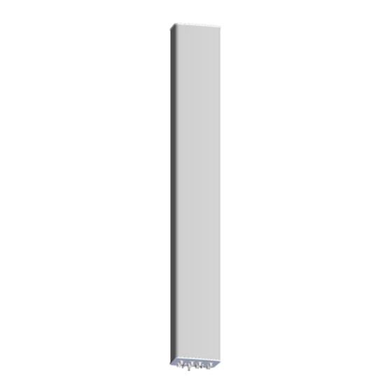
Instruction Manual, 353mm (13.9") Profile Panel Antennas
Bulletin A997-0083 · Revision H · March 2015 page 1 of 7
CommScope Infrastructure Academy offers installation training
General
This instruction manual contains all necessary information required to assist in the correct
installation of ARGUS Panel Antennas of 353mm (13.9") width to a 75 – 115mm (3" - 4.5")
diameter pipe when using the mounting kit with clamp bracket. These antennas can be
supplied with either fixed beam downtilt, manually adjustable electrical downtilt or AISG-
compatible remotely controlled electrical downtilt. Mechanical downtilt is also available if
required, depending on the type of mounting kit selected.
Following symbols can be found next to text outlining important information.
Please follow the procedure marked with this symbol precisely.
Non-compliance may lead to damage of the product.
Handy tips when installing product.
Unpacking
Make sure that the antenna and the accessory items listed below are provided and have not
been damaged during transport.
• Antenna
• Mounting kit (mounting kit components for each configuration are shown in Figures
2 and 3).
• Hex key 6mm AF (supplied with adjustable downtilt antennas only).
600mm – 870mm
Mounting Kit
Type
Fixed Downtilt
Mechanical
Downtilt
Tilt range
0° -15° in 3° steps
Mounting
Bracket Spacing
Dim A (Fig 4)
Table 1: Mounting Kit Part Numbers for Different Antennas
®
Argus
870mm – 1200mm
(23.6" – 34.3")
(34.3" – 43.3")
Antennas
F-042-GL-E
T-095-GL-E
0°, 2° -10° in 1°
480mm (18.9")
716mm (28.2")
Installation
1200mm – 1575mm
Antennas
F-042-GL-E
T-045-GL-E
0° - 12° in 1° steps
steps
976mm (38.4")
1575mm – 2700mm
(43.3" – 62")
Antennas
F-042-GL-E
T-041-GL-E
0° - 8° in 1° steps
1400mm (55.1")
(62" – 106.3")
Antennas
F-042-GL-E
T-029-GL-E
Advertisement

Related Manuals for Andrew CommScope Argus


Summary of Contents for Andrew CommScope Argus
- Page 1 Installation ® Argus Instruction Manual, 353mm (13.9”) Profile Panel Antennas Bulletin A997-0083 · Revision H · March 2015 page 1 of 7 CommScope Infrastructure Academy offers installation training General This instruction manual contains all necessary information required to assist in the correct installation of ARGUS Panel Antennas of 353mm (13.9") width to a 75 –...
-
Page 2: Installation Instructions
Instruction Manual, 353mm (13.9”) Profile Panel Antennas Bulletin A997-0083 · Revision H · March 2015 page 2 of 7 DO NOT STACK UNPACKED ANTENNAS DO NOT PLACE POINT LOADS ON ANTENNA RADOME Installation Instructions Ensure a torque spanner is used when tightening fasteners, see the mounting kit diagrams on the following pages for the correct torque recommendations. - Page 3 Instruction Manual, 353mm (13.9”) Profile Panel Antennas Bulletin A997-0083 · Revision H · March 2015 page 3 of 7 USE MOUNTING BRACKETS FOR LIFTING AS SHOWN Do not install near power lines. Power lines, Do not install on a wet or windy day or Wear shoes with rubber soles and heels.
- Page 4 Instruction Manual, 353mm (13.9”) Profile Panel Antennas Bulletin A997-0083 · Revision H · March 2015 page 4 of 7 Lower Mounting Bracket Assembly Upper Mounting Bracket Assembly (To Suit Pipes OD 75-115 mm) ( To Suit Pipes OD 75-115 mm) Figure 1: Correctly Assembled Mounting Kit Using Clamp Bracket for Mechanically Adjustable Downtilt Antenna Figure 2: Typical Exploded Assembly for Upper Mounting Bracket using Clamp...
- Page 5 Instruction Manual, 353mm (13.9”) Profile Panel Antennas Bulletin A997-0083 · Revision H · March 2015 page 5 of 7 Figure 3: Exploded Assembly for Lower Mounting Bracket using Clamp Bracket (This configuration should also be used for the upper Mounting Bracket when 0° tilt is required) OPTIONAL: THE TILT ARM AND EXTRA HARDWARE CAN BE STOWED IN THE POSITION SHOWN WHEN IN...
- Page 6 Instruction Manual, 353mm (13.9”) Profile Panel Antennas Bulletin A997-0083 · Revision H · March 2015 page 6 of 7 Each RF and/or AISG port on the antenna is numbered and identified in Port and Band accordance with AISG Standard “AISG Antenna Port Color Coding”. Identification Each RF band in the antenna corresponds with a pair of ±45°...
- Page 7 Instruction Manual, 353mm (13.9”) Profile Panel Antennas Bulletin A997-0083 · Revision H · March 2015 page 7 of 7 End Cap Layout for Typical Antennas Tilt adjust and scale (Band 1) Tilt adjust and scale Tilt adjust and scale (Band 2) (Band 3) Figure 5: Typical 6-port (CVVPX) with internal...
- Page 8 North America: +1-800-255-1479 (toll free) (828) 324-2200 (800) 982-1708 Any country: +1-779-435-6500 www.commscope.com/andrew email: acicustomersupportcenter@commscope.com Notice: CommScope disclaims any liability or responsibility for the results of improper or unsafe installation, inspection, maintenance, or removal practices. Aviso: CommScope no acepta ninguna obligación ni responsabilidad como resultado de prácticas incorrectas o peligrosas de instalación, inspección, mantenimiento o retiro.
Need help?
Do you have a question about the CommScope Argus and is the answer not in the manual?
Questions and answers