
Related Manuals for Clear-Com HME DX210


Summary of Contents for Clear-Com HME DX210
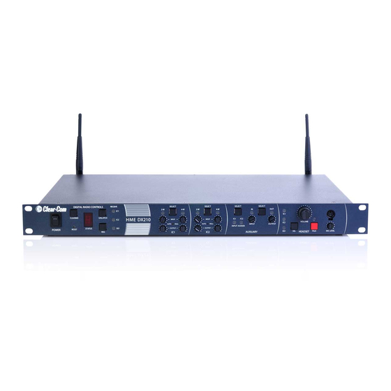
- Page 1 Clear-Com HME DX210 Dual-Channel Wireless Intercom Operating Instructions HME# 400G661 Rev B 6/2/11...
- Page 3 No part of this document may be reproduced in any form by any means without prior written authorization of Clear-Com, an HME Company. Clear-Com Offices are located in California, USA; Cambridge, UK; Montreal, Canada; and Beijing, China.
-
Page 4: Fcc Notice
Changes or modifications not expressly approved by Clear-Com, LLC, an HM Electronics, Inc. company could void the user’s authority to operate this equipment. - Page 5 (manufacturers, distributors and/or retailers) to take-back electronic products at the end of their useful life. The WEEE Directive covers most Clear-Com products being sold into the EU as of August 13, 2005. Manufacturers, distributors and retailers are obliged to finance the costs of recovery from municipal collection points, reuse, and recycling of specified percentages per the WEEE requirements.
-
Page 6: Table Of Contents
Appendix A: COMMUNICATOR Indicator Light Functions............20 Appendix B: Multiple Base Station Daisy-Chaining ..............21 Appendix C: Jumper Settings ......................22 Appendix D: Multiple Base Station Registration................23 Appendix E: Interference Avoidance through Spectrum Friendly..........25 Appendix F: Audio Routing Diagram....................27 Clear-Com HME DX210 System Guide... -
Page 7: System Overview
In the single-channel mode, any 4 Communicators can transmit at the same time. This number can be increased by adding up to 3 additional base stations. The DX210 supports both Clear-Com and RTS cabled 2-wire intercom systems, and also has 4-wire and auxiliary audio connections. -
Page 8: Base Station Front Panel
49. AUX OUT Connector 42. IC1 2-W XLR-3F Connector 50. Relay Connector 43. CLEAR-COM/RTS Select Switch 51. DC Power Connector 44. IC2 2-W XLR-3F Connector 52. ANT (R-TNC) 45. IC2 2-W XLR-3M Connector 53. Chassis Grounding Screw Clear-Com HME DX210 System Guide... -
Page 9: Belt Pack - Bp210
5. IC1 (Intercom 1) button 10. Battery-release latch 1.5 All-In-One Headset – WH210 Battery Power/mode lights Battery-release latch IC1 (Intercom 1) button Power button IC2 (Intercom 2) button Volume-up button Volume-down button ISO (Isolate) button Clear-Com HME DX210 System Guide... -
Page 10: System Setup
Power cord To electrical cable connector connector outlet Battery Charger AC power supply Power cord The red lights on the charger will come on briefly, and then the yellow lights will come on and stay on. Clear-Com HME DX210 System Guide... -
Page 11: Charge Batteries
NOTE: Batteries should not be left in charge ports after being fully charged. If a battery is left in a charge port for m ore than three weeks, the yellow indicator may light up. In this case, it does not indicate a faulty battery. Clear-Com HME DX210 System Guide... -
Page 12: Basic Base Station Setup
(# ) on the front panel to turn on the base station. A red light on the switch should go on. If you have more than one base station, refer to Appendix D, page 23 for multiple base station registration. Clear-Com HME DX210 System Guide... -
Page 13: Communicator
Power inserted first. Press it in until it snaps. inserted first. Press it in until it snaps. button Clear-Com HME DX210 System Guide Clear-Com HME DX210 System Guide... -
Page 14: Register Communicator ® S
Press the RESET button at the lower-left corner of the base station with a pen or similar pointed object. When the STATUS display becomes blank, press the REG button and register the Communicator again. If registration fails again, call your dealer for assistance. Clear-Com HME DX210 System Guide... -
Page 15: Communicator ® Settings
Decrease sidetone level (5 steps) * NOTE: There is no sidetone adjustment function for All-In-One Headsets. Power button NOTE: If you are not connecting a wired intercom, go on to System Operation, section 3, page 13. Clear-Com HME DX210 System Guide... -
Page 16: Interfacing With 2-Wire Or 4-Wire Intercoms
NOTE: If no power is detected at the 2-W connector, the 2-W light will come on red and no audio will be passed through. Plugging in a connection to a Clear-Com or RTS power supply, at this point, will turn the light green and operation will begin. -
Page 17: Interfacing With Auxiliary Audio Equipment
B ase station rear panel The cable connectors must be 3- XLR type for balanced +20dBu Pin 1 = Ground maximum audio input/output, wi Pin 2 = Audio + e following pin connections: Pin 3 = Audio – Clear-Com HME DX210 System Guide... -
Page 18: Iso Relay
During ISO communication, a relay closure is provided. This can be used for tasks such as keying a long nge radio or trigge ring an alert light. It can be activated from a Communicato r or a local headset. Base station rear panel Clear-Com HME DX210 System Guide... -
Page 19: System Operation
TALK light indicates the TALK mode is active via the local headset. ● Use the VOLUME control to adjust the output to the local headset earpiece. ● Use the MIC LEVEL control to adjust the audio level from the local headset microphone. Clear-Com HME DX210 System Guide... -
Page 20: Communicator ® Operation
If you press and hold the volume- down button, repeating beeps will be heard as the volume steps down to minimum. When minimum volume is reached, rapidly repeating beeps will be heard. Clear-Com HME DX210 System Guide... -
Page 21: Adjusting Microphone Gain
When replacing a battery, place the end of the battery with the metal contacts into the battery holder, in the same position as the battery you removed. Press the top of the battery carefully into the battery holder until it snaps in place under the battery-release latch. Clear-Com HME DX210 System Guide... -
Page 22: Troubleshooting
Plug into 2-W power supply. If the lack of powered 2-W system is intentional (such as when using a Clear-Com MT1, or when daisy-chaining multiple base stations), open the base station cover and set JP1 (IC1) and/or JP2 (IC2) to the ON position. If daisy-chaining, do not forget to also terminate one of the base stations by setting JP5 (IC1) and/or JP6 (IC2) to ON. -
Page 23: Technical Data
Gaussian filtered FSK, TDMA Frequency Stability: 13 ppm Harmonics/Spurious: Exceeds FCC and ETSI specifications over temperature BASE STATION RECEIVER Type: RF Sensitivity: Frequency Hopping, Spread Spectrum <-90dBm w 10-3 BER Frequency Stability: 13 ppm Distortion: <2% Clear-Com HME DX210 System Guide... -
Page 24: Bp210 Belt Pack Specifications
Modulation Type: Gaussian filtered FSK, TDMA Frequency Stability: 13 ppm Harmonics/Spurious: Exceeds FCC and ETSI specifications BELT PACK RECEIVER Type: RF Sensitivity: Frequency Hopping, Spread Spectrum <-90dBm w 10-3 BER Frequency Stability: 13 ppm Distortion: <2% Clear-Com HME DX210 System Guide... -
Page 25: Wh210 All-In-One Headset Specifications
Modulation Type: Gaussian filtered FSK, TDMA Frequency Stability: 13 ppm Harmonics/Spurious: Exceeds FCC and ETSI specifications HEADSET RECEIVER Type: RF Sensitivity: Frequency Hopping, Spread Spectrum <-90dBm w 10-3 BER Frequency Stability: 13 ppm Distortion: <2% Clear-Com HME DX210 System Guide... -
Page 26: Appendix A: Communicator ® Indicator Light Functions
IC1 Idle Steady Green IC1 TX Blinks Green Steady Green IC2 Idle Steady Red IC2 TX Blinks Red Steady Green ISO TX Blinks Red or Green Steady Red (depending on previous Mode) Low battery No indication Clear-Com HME DX210 System Guide... -
Page 27: Appendix B: Multiple Base Station Daisy-Chaining
Two or more DX210 base stations can be “daisy-chained” together with cables connected to the 2-W ® ® connectors on the rear panels of each base station, following Clear-Com / RTS standards, or two base stations (not more) can be “daisy-chained” together with cables connected to the 4-W or AUX connectors. -
Page 28: Appendix C: Jumper Settings
If termination of the base station is necessary (such as when multiple base stations are daisy chained), set the JP5 (IC1) and/or JP6 (IC2) jumpers to the ON position on one base station, when connecting multiple base station together via 2-wire connection. Only one base station should be terminated per channel. Clear-Com HME DX210 System Guide... -
Page 29: Appendix D: Multiple Base Station Registration
Press the REG button on the primary. The STATUS display will go blank. ● Register Communicators to the secondary base stations as instructed in section 2.3.2, page 8 . After registration, turn off the secondary base station and all Communicators. Clear-Com HME DX210 System Guide... - Page 30 Communicators registered during primary operation. For secondary base stations, the Communicators must always be registered after secondary base station registrati on, with the primary base station remaining active and the secondary base station displaying one bar. Clear-Com HME DX210 System Guide...
-
Page 31: Appendix E: Interference Avoidance Through Spectrum Friendly
COMMUNICATOR s to be used with each base station as instructed in section 2.3.2, page NOTE: If you change a base station’s frequency band setting, you will have to re-register all Comm unicators that were registered to that base station. Clear-Com HME DX210 System Guide... - Page 32 Your DX210 should be set to the high or low band opposite any Wi-Fi frequency range in use. DX210 Low Band = 2.4000-2.4400 GHz DX210 High Band = 2.4433-2.4830 GHz Channel Wi-Fi Frequencies 2.412 2.417 2.422 2.427 2.432 2.437 2.442 2.447 2.452 2.457 2.462 2.467 2.472 2.484 GHz Clear-Com HME DX210 System Guide...
-
Page 33: Appendix F: Audio Routing Diagram
Appendix F: Audio Routing Diagram Clear-Com HME DX210 System Guide... - Page 34 有毒有害物质或元素表 Table of Toxic and Hazardous Substances 部件名称 有毒有害物质或元素 Names of Parts Toxic and Hazardous Substances or Elements 铅 镉 汞 六价铬 多溴联苯 多溴二苯醚 Cr6+ PBDE BS210 基站 Top assembly BS210 (G28707-1A1) 基站电路板 Audio PCB (G28718-1) 收发器电路板 Front Panel PCB (G28729-1) 收发器电路板...
- Page 35 有毒有害物质或元素表 Table of Toxic and Hazardous Substances 部件名称 有毒有害物质或元素 Names of Parts Toxic and Hazardous Substances or Elements 铅 镉 汞 六价铬 多溴联苯 多溴二苯醚 Cr6+ PBDE BP210 对讲机 Top Assembly BP210 (G27830-1A1) 对讲机电路板 XCVR PCB (G27560-1H1) HS15 耳机 HS15/D Headset (306G100-1 /306G101- 对讲机套...
- Page 36 表的有毒有害物质 Table of Toxic and Hazardous Substances 部件名称 有毒有害物质或元素 Names of Parts Toxic and Hazardous Substances or Elements 铅 镉 汞 六价铬 多溴联苯 多溴二苯醚 Cr6+ PBDE WH210 头佩戴式耳麦 Top Assembly WH210 (G28741-1Z1) 耳机电路板 (G28055-1F1) 电池 Battery (104034) O: 表示该有毒有害物质在该部件所有均质材料中的含量均在SJ/T11363-2006标准规定的限量要求以下。 O: Indicates that this toxic or hazardous substance contained in all of the homogeneous materials for this part is below the limit requirements in SJ/T11363-2006 X: 该有毒有害物质至少在该部件的某一均质材料中的含量超出SJ/T11363-2006标准规定的限量要求。...
Need help?
Do you have a question about the HME DX210 and is the answer not in the manual?
Questions and answers