Sign In
Upload
Download
Table of Contents
Contents
Add to my manuals
Delete from my manuals
Share
URL of this page:
HTML Link:
Bookmark this page
Add
Manual will be automatically added to "My Manuals"
Print this page
×
Bookmark added
×
Added to my manuals
Manuals
Brands
Clear-Com Manuals
Intercom System
WBS-680
Operating instructions manual
Clear-Com WBS-680 Operating Instructions Manual
Professional wireless intercom system
Hide thumbs
1
2
Table Of Contents
3
4
5
6
7
8
9
10
11
12
13
14
15
16
17
18
19
20
21
22
23
24
25
26
27
28
29
30
31
32
33
34
35
36
37
38
39
40
41
42
43
44
45
46
47
48
49
50
51
52
53
54
55
56
57
58
59
60
61
62
63
64
65
66
67
68
69
70
71
72
73
74
75
76
77
78
79
80
81
82
83
84
85
86
page
of
86
Go
/
86
Contents
Table of Contents
Bookmarks
Table of Contents
Table of Contents
In Tro Duc Tion
Gen Eral de Scrip Tion
Sys Tem Fea Tures
WBS-680 Base Sta Tion
Con Trols and con Nec Tions - Front Panel
Con Trols and con Nec Tions - Rear Panel
WBS-680 Spec I Fi Ca Tions
WTR-680 Beltpack
Con Trols and con Nec Tions - Top Panel
Con Trols and con Nec Tions - Rear Panel
WTR-680 Spec I Fi Ca Tions
WTR-682 Beltpack
Con Trols and con Nec Tions - Top Panel
WTR-682 Beltpack
Con Trols and con Nec Tions - Rear Panel
WTR-682 Spec I Fi Ca Tions
Ini Tial Equip Ment Set-Up
Un Packing
An Tenna con Nec Tions
An Tenna Po Lar Iza Tion
Dis Tance be Tween an Tennas
An Tenna Place Ment
IM Proving Re Cep Tion/In Creasing Range
Base Sta Tion Set-Up
Lo Ca Tion
Power con Nec Tion
Trans mit Switches
In Ter Nal Trans mit Switches
In Ter Com Switch
In Ter Com in Ter Face
Dual Lis Ten Func Tion al Ity
Aux Il Iary in Put/Out Put
In Ter Nal aux Il Iary in Put Routing Switch
Stage an Nounce /Re Lay con Tacts
Base Sta Tion Link
Beltpack Set-Up
Bat Tery in Stal la Tion
An Tenna con Nec Tion
Trans mit Mode
Head Set con Nec Tion
Pre-Walk-Thru Check List
System Op er a Tion
Fre Quency Plan over View
Fac Tory-Defined Group
User-Programmable Groups
Sys Tem Quick Start
Base Sta Tion Op er a Tion
Power
Lo Cal Head Set
Por Ta Ble Sta Tion con Nect
In Ter Com a and B
Aux Il Iary
Dis Play con Trast
Main Screen Flowchart
WBS-680 Menu Struc Ture
Beltpack Ac Tiv Ity Code Def I ni Tions
Op er Ating Screen
Power-Up Screen
Group/Chan Nel Se Lect
Group/Fre Quency Se Lect
Fre Quency Edit
Scan
1St Use de Fault
Copy
Fac Tory de Fault
Lock out
Spe Cial Key Se Quences
Power/Lo Cal Head Set Vol Ume
Bat Tery Check
Talk but Ton
MI Cro Phone Gain
Chan Nel Se Lect but Ton
Stage an Nounce (SA)
Wire Less Talk Around (WTA)
WTR-680 Beltpack Menu Struc Ture
Power-Up Screens
Group/Chan Nel Screen
Trans mit Screen
Re Ceive 1 Screen
Re Ceive 2 Screen
Stage an Nounce en Able/Dis Able
Wire Less Talk Around en Able/Disable
Talk but Ton Latch On/Latch off
1St Use de Fault
Fac Tory de Fault
Lock out
Spe Cial Key Se Quences
Clearscan™
Power-Up Screens
Group/Chan Nel Screen
Trans mit Screen
Re Ceive 1 Screen
Re Ceive 2 Screen
Au Dio Output
Scan
Stage an Nounce en Able/Disable
Wire Less Talk Around
Au Dio Chan Nel a Options
Au Dio Chan Nel B Op Tions
1St Use de Fault
Fac Tory de Fault
Lock out
Spe Cial Key Se Quences
Sys Tem Walk-Thru
Trou Ble Shooting
Tech Tips
Fre Quency in Ter Ac Tion
MI Cro Phone Gain Ad Just Ment
Bat Tery in for Ma Tion
In Ter Com Sys Temspec I Fi Ca Tions
Ac Ces Sories and Re Place Ment Parts
FCC in for Ma Tion
Cus Tomer Ser Vice in for Ma Tion
Limited Warranty
Advertisement
Quick Links
1
Wbs-680 Base Sta Tion
2
Wtr-680 Beltpack
3
Con Trols and con Nec Tions - Top Panel
4
Wtr-682 Beltpack
Download this manual
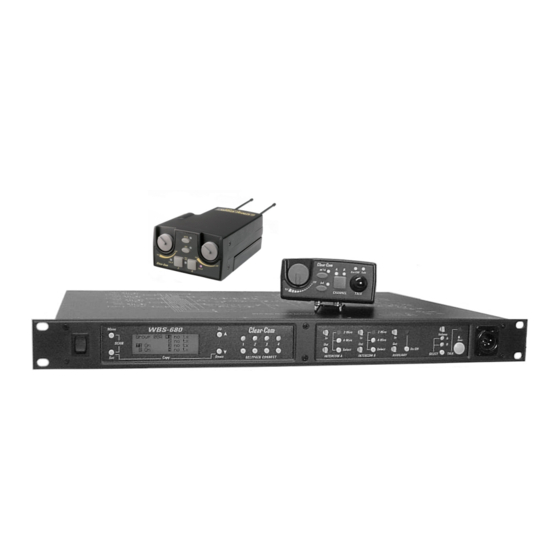
Op er ating In struc tions
WBS-680, WTR-680, WTR-682
Pro fes sional
Wire less
In ter com Sys tem
R
Intercom Systems
Table of
Contents
Previous
Page
Next
Page
1
2
3
4
5
Advertisement
Table of Contents
Need help?
Do you have a question about the WBS-680 and is the answer not in the manual?
Ask a question
Questions and answers
Related Manuals for Clear-Com WBS-680
Intercom System Clear-Com WTR-670 Operating Instructions Manual
Professional wireless intercom system (62 pages)
Intercom System Clear-Com WBS-670 Operating Instructions Manual
Professional wireless intercom system (62 pages)
Intercom System Clear-Com WTR-680 Operating Instructions Manual
Professional wireless intercom system (86 pages)
Intercom System Clear-Com WBS Operating Instructions Manual
Wireless intercom system (13 pages)
Intercom System Clear-Com WBS Operating Instructions Manual
Wireless intercom system (15 pages)
Intercom System Clear-Com HME DX410 User Manual
Dual-channel wireless intercom (38 pages)
Intercom System Clear-Com HME DX210 Operating Instructions Manual
Dual-channel wireless intercom (43 pages)
Intercom System Clear-Com HMS-4X Technical Manual
Ip network guidance: helixnet digital partyline (22 pages)
Intercom System Clear-Com Eclipse HX User Manual
(259 pages)
Intercom System Clear-Com FreeSpeak II User Manual
(143 pages)
Intercom System Clear-Com Eclipse HX-Delta User Manual
(193 pages)
Intercom System Clear-Com FreeSpeak II FSII-TCVR-24 User Manual
For eclipse hx (102 pages)
Intercom System Clear-Com TEMPEST 2400 Reference Manual
Wireless intercom system (100 pages)
Intercom System Clear-Com ENCORE MS-702 Instruction Manual
Two-channel main station (32 pages)
Intercom System Clear-Com MS-200C Instruction And Service Manual
(27 pages)
Intercom System Clear-Com LQ-2W2 User Manual
Lq 4.0 series (181 pages)
This manual is also suitable for:
Wtr-680
Wtr-682
Table of Contents
Print
Rename the bookmark
Delete bookmark?
Delete from my manuals?
Login
Sign In
OR
Sign in with Facebook
Sign in with Google
Upload manual
Upload from disk
Upload from URL


Need help?
Do you have a question about the WBS-680 and is the answer not in the manual?
Questions and answers