
Related Manuals for Clear-Com HME DX410


Summary of Contents for Clear-Com HME DX410
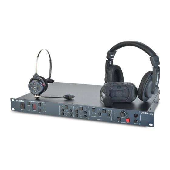
- Page 1 User Guide Clear-Com HME DX410 Dual-Channel Wireless Intercom Part Number: 399G162 Rev B Date: 1/27/16...
- Page 2 Clear-Com, an HME Company. Clear-Com Offices are located in California, USA; Cambridge, UK; Montreal, Canada; and Beijing, China. Addresses and contact information can be found on Clear-Com’s corporate website at www. clearcom.com.
-
Page 3: Fcc Notice
Operation of this equipment in a residential area is likely to cause harmful interference, in which case the user will be required to correct the interference at his own expense. Changes or modifications not expressly approved by Clear-Com, LLC, an HM Electronics, Inc. company could void the user’s authority to operate this equipment. - Page 4 Hereby, Clear-Com, LLC, an HM Electronics, Inc, company, declares that the DX410 is in compliance with the essential requirements and other relevant provisions of R&TTE Directive 1999/5/EC. In AFH mode, complies with European Telecommunications Standards Institute (ETSI) harmonized European standard EN 300 238 v1.8.1.
-
Page 5: Table Of Contents
TABLE OF CONTENTS System Overview ..............6 System Components . -
Page 6: System Overview
Communicators can operate in full duplex mode. This number can be increased by adding up to three additional base stations. The DX410 supports both Clear-Com and RTS cabled 2-wire intercom systems, and also has 4-wire and auxiliary audio connections. -
Page 7: Base Station Front Panel
Base Station Front Panel 18 20 22 21 26 28 Digital Radio Controls 20. (B) AUTO NULL button (recessed) 1. POWER switch 21. (B) 4-W input level adjust 2. CLR/BND button 22. (B) 4-W output level adjust 3. RESET button (recessed) 23. -
Page 8: Base Station Rear Panel
11. AUX IN Connector 4. (A) 2-W XLR-3M Connector 12. AUX OUT Connector 5. (A) 2-W XLR-3F Connector 13. Relay Connector 6. CLEAR-COM/RTS Select Switch 14. DC Power Connector 7. (B) 2-W XLR-3F Connector 15. ANT (R-TNC) 8. (B) 2-W XLR-3M Connector 16. -
Page 9: All-In-One Headset - Wh410
All-In-One Headset – WH410 1. Channel A (Intercom 1) button 6. Power/mode lights 2. ISO (Isolate) button 7. Microphone 3. Volume-up button 8. Power button 4. Volume-down button 9. Battery 5. Channel B (Intercom 2) button 10. Battery-release latch... -
Page 10: System Setup
SYSTEM SETUP Displayed below is an example of a typical Clear-Com set up and configuration with the DX410. Battery Charging Before installing the system, connect the AC power supply to the battery charger and plug it into an electrical outlet. Charge all the batteries while the other equipment is being installed. -
Page 11: Charging The Batteries
Batteries in Charging ports Batteries in Storage ports Charging the Batteries Up to four batteries can be charged in the battery charger at one time. The battery status lights next to each charging port indicate the battery status. Up to four fully charged batteries can be stored in the battery Storage ports. Insert a battery in each of four Charging ports until it clicks in place. -
Page 12: Basic Base Station Setup
Basic Base Station Setup This section describes setup and equipment connections for an individual base station. 90° SINGLE/DUAL Channel select switch Base station rear panel AC power supply AC power cord Connect the two enclosed antennas to the antenna connectors on the rear panel of the base station, and turn the sleeves clockwise on the antenna connectors to tighten them securely in place. -
Page 13: Communicator
COMMUNICATOR Setup and Registration ® The first time you operate the DX410 system, you must register each Communicator (Belt Pack and/or All-In-One Headset) for use with a specific base station. The base station will then recognize all registered Communicators when their power is on and will differentiate between them and other electronic equipment operating on the same frequencies. - Page 14 All-In-One Headsets Changing Batteries When a battery weakens, a prompt in the headset will say “Change battery”. Remove the battery from the headset by pressing the blue battery-release latch. Battery-release latch Insert a fully charged battery in each Headset, with the battery’s (blue button) metal contacts inserted first.
- Page 15 ® Register COMMUNICATOR The Communicator must be within 6 feet (1.83 meters) of the base station to enable registration. Be certain all headsets to be registered are turned OFF, and the base station power is ON. Place the headset on your head. Press the REG button on the front panel of the base station.
- Page 16 ® COMMUNICATOR Settings If you want to set up a Communicator with any of the special settings shown below, press and hold the specified button combinations during or after power up. These settings will remain in memory when the Communicators are turned off and on again.
-
Page 17: Interfacing With 2-Wire Or 4-Wire Intercoms
NOTE: If no power is detected at the 2-W connector, the 2-W light will illuminate red and no audio will be passed through. Plugging a connection into a Clear-Com or RTS power supply will turn the light green and operation will begin. -
Page 18: Interfacing With Auxiliary Audio Equipment
A and B Intercom Controls and Indicator Lights Base station front panel The A portion of this area of the panel is for Intercom Channel A, and the B portion is for Intercom Channel 2. Their operation is identical. The SELECT button ( ) is used to select 2-Wire ( ) or 4-Wire ( ) or both. -
Page 19: Iso Relay
The AUXILIARY SELECT button ( ) is used to select A or B or both as the destination for AUX IN audio. The A and/ or B INPUT ASSIGN lights ( ) come on green to indicate the selection as the destination for AUX IN audio. If neither is ®... -
Page 20: System Operation
SYSTEM OPERATION ® This chapter describes how to operate the Base Station and COMMUNICATOR (Belt Pack or All-In-One Headset). Base Station Operation ® COMMUNICATOR Audio Channel and Local Headset Registration Auto-Null Controls Connector & Controls Power Switch AUX IN Assign and AUX In/Out Controls System and Registration Controls and Indicator Lights The CLR/BND button, RESET button, STATUS indicator and REG button are used when registering... -
Page 21: Communicator ® Operation
COMMUNICATOR ® OPERATION Belt Pack control buttons have a snap action. They will activate when pressed firmly. Use your fingertips (not your fingernails) to press the Belt Pack buttons. All-In-One Headset buttons are touch sensitive. Power On/Off Power On – Press and release the Power button (PWR). A voice prompt in the ear piece will say “Battery Level”, and the red power lights near the corners of the A and B buttons will turn on. -
Page 22: Adjusting Microphone Gain
Adjusting Microphone Gain Some users talk louder/softer than others. To allow for this, microphone gain adjustment is available. To increase microphone gain – While holding down the B button, press the volume-up ▲ button as many times as necessary to reach the desired level. The microphone gain increase can be monitored through side tone, or preferably by someone else using a Communicator or at the base station. -
Page 23: Eu Base Station Adaptive Frequency Hopping
EU BASE STATION ADAPTIVE FREQUENCY HOPPING Background The Clear-Com DX wireless intercom systems utilize a Frequency Hopping Spread Spectrum (FHSS) radio in order to provide robust communications. This system operates in the unlicensed 2.4 GHz band. With the proliferation of other devices over the past few years in the same 2.4 GHz band, instances where these devices and systems can interfere with each other has greatly increased. - Page 24 Wi-Fi transmission at a fixed location. NOTE: If the Clear-Com system does not have AFH, then the base station should be set to operate in the region of the 2.4 GHz band where the Wi-Fi access point is not operating. For example, if the Wi-Fi access point is set to Wi-Fi channel 1, the base station should be set to operate in the ‘High’...
- Page 25 Spectral efficiency. Wi-Fi systems employ a standard sometimes referred to as 802.11. The number “11” is simply the number given to the standard by the Institute of Electrical and Electronics Engineers (the IEEE). Modern Wi-Fi routers will allow operation employing the 802.11n mode. This mode will allow higher data rates, but it also may consume twice the number of radio channels.
-
Page 26: Troubleshooting
Plug into 2-W power supply. If the lack of powered 2-W system is intentional (such as when using a Clear-Com MT1, or when daisy-chaining multiple base stations), open the base station cover and set JP1 (A) and/or JP2 (B) to 2-W LEDs remain red. -
Page 27: Technical Data
4-Wire I/O RJ45, 600Ω balanced, level adjustable, simultaneous operation with 2-wire ® ® XLR-3M, XLR-3F, externally-switchable RTS or Clear-Com mode, 2-Wire I/O 200Ω, level adjustable, null adjustable to 50dB attenuation, typical Auxiliary Input XLR-3F/¼” (6.35 mm) combo jack, 600Ω balanced, level adjustable Auxiliary Output XLR-3M, 600Ω... -
Page 28: Bp410 Belt Pack Specifications
BP410 Belt Pack Specifications General Channels 2 audio channels Frequency Range 2400 – 2483.5 MHz Antenna Internal, horizontal/vertical diversity Frequency Response 200 Hz to 7 kHz Battery Requirements 3.6V lithium ion Battery Life Up to 20 hours Temperature Range 32-122°F (0-50°C) Weight 7.4 oz (.21 kg) with battery and pouch Headset Connector... -
Page 29: Wh410 All-In-One Headset Specifications
WH410 All-In-One Headset Specifications General Channels 2 audio channels Frequency Range 2400 – 2483.5 MHz Antenna Internal Frequency Response 200 Hz to 7 kHz Battery Requirements 3.6V lithium ion Battery Life Up to 20 hours Temperature Range 32-122°F (0-50°C) Weight 5.7 oz (.16 kg) with battery Microphone Electret... -
Page 30: Appendix A: Communicator ® Indicator Light Functions
APPENDIX A: COMMUNICATOR Indicator Light Functions ® BP410 Belt Pack Indicator Lights BP410 Condition A Indicator Light B Indicator Light A Idle Steady Green A TX Blinks Green B Idle Steady Green B TX Blinks Green ISO TX Blinks Green Blinks Green Low battery Appropriate channel light Blinks Red when in idle mode... -
Page 31: Appendix B: Multiple Base Station Daisy-Chaining
Two or more DX410 base stations can be “daisy-chained” together with cables connected to the 2-W connectors on the ® ® rear panels of each base station (following Clear-Com / RTS standards), or two base stations (not more) can be “daisy- chained”... -
Page 32: Appendix C: Jumper Settings
APPENDIX C: JUMPER SETTINGS The base station has internal jumpers that are used to set ISO broadcast restrict, power detect by-pass, and 2-wire channel termination. Jumper # Function Default Split ‘ISO’ ISO No Broadcast Channel A, 2-wire termination Ch A 4w to 2w audio bridge Ch B 4w to 2w audio bridge JP10 Ch A 2w to 4w audio bridge... -
Page 33: Appendix D: Interference Avoidance Through Spectrum Friendly
APPENDIX D: INTERFERENCE AVOIDANCE THROUGH SPECTRUM FRIENDLY Interference, which may be heard in a headset as popping sounds, may occur whenever other equipment such as Wi-Fi systems or wireless DMX systems use the same frequency band. Some systems can be limited to one portion of the band. If so, the DX410 can be set to the opposite half of the 2.4 GHz to 2.48 GHz band. -
Page 34: Spectrum Friendly
Wait until “c” appears on the display. NOTE: A “c” will only appear on the STATUS display if you are setting the frequency band the first time, or you are changing the setting. If you stop at L, H or A that was already set, an “8” will appear for a few seconds and the STATUS display will become blank. -
Page 35: Appendix E: Audio Routing Diagram
APPENDIX E: AUDIO ROUTING DIAGRAM CH. B 2WT04W CH. B 4WT02W CH. A 2WT04W CH. A 4WT02W...
Need help?
Do you have a question about the HME DX410 and is the answer not in the manual?
Questions and answers