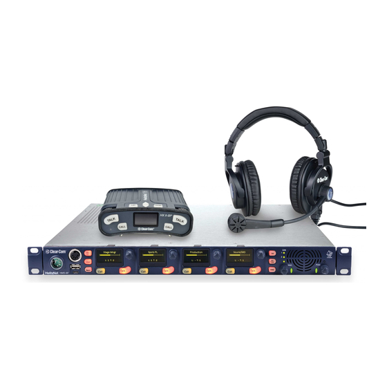
Clear-Com HelixNet Partyline User Manual
Hide thumbs
Also See for HelixNet Partyline:
- Technical manual (22 pages) ,
- User manual (285 pages) ,
- Quick start manual (2 pages)
Table of Contents
Advertisement
Quick Links
Advertisement
Table of Contents

Related Manuals for Clear-Com HelixNet Partyline


Summary of Contents for Clear-Com HelixNet Partyline
- Page 1 Partyline User Guide PN: 399G052 Rev: B 06/19/13...
-
Page 2: Document Reference
Copyright © 2013 HME Clear-Com Ltd. All rights reserved. Clear-Com, the Clear-Com logo, and Clear-Com Concert are trademarks or registered trademarks of HM Electronics, Inc. The software described in this document is furnished under a license agreement and may be used only in accordance with the terms of the agreement. -
Page 3: Table Of Contents
HBP-2X connectors and controls (rear view) ..............25 2.3.3 HBP-2X beltclip, beltloops and feet (base view) ..............27 Installing HelixNet Partyline................. 28 Planning your HelixNet Partyline installation ................29 3.1.1 Comparing digital with analog cabling ................29 3.1.2 Topologies (layouts) ......................31 Installing HelixNet Partyline ...................... - Page 4 Configuring a Four-wire interface module ................57 5.6.2 Configuring a Two-wire interface module ................59 5.6.3 Configuring an Ethernet or Fiber interface module ............. 63 5.6.4 Configuring the Module Settings: Version information ............65 Administration ..........................65 HelixNet Partyline User Guide...
- Page 5 Viewing powerline information and status ................79 Using the HMS-4X Main Station ................80 Using the gooseneck mic, loudspeaker and headset ..............80 7.1.1 Switching between the headset mic and the gooseneck mic ..........82 Entering and exiting Menu mode ....................82 HelixNet Partyline User Guide...
- Page 6 9.1.3 Connecting to an Encore Main Station ................89 9.1.4 Connecting to Encore remote stations ................90 Connecting HelixNet Partyline to RTS (Telex) two-wire systems ..........90 9.2.1 About RTS two-wire systems ....................90 9.2.2 Quick reference: Two-wire connection to RTS 2W system ..........91 9.2.3...
- Page 7 Environmental ........................121 10.3 Four-wire module: general ......................122 10.3.1 Connectors ........................122 10.3.2 Dimensions and weight ..................... 122 10.3.3 Environmental ........................122 10.4 Beltpack (HBP-2X) ........................123 10.4.1 Connectors ........................123 10.4.2 Microphone pre-amplifier ....................123 HelixNet Partyline User Guide...
- Page 8 10.4.3 Headphone amplifier ......................124 10.4.4 Power requirements ......................124 10.4.5 Environmental ........................124 Appendix A: Compliance ..................125 Appendix B: Menu maps ..................127 Appendix C: Cabling reference ................138 Appendix D: Troubleshooting ................140 HelixNet Partyline User Guide...
-
Page 9: Introduction
HelixNet Partyline is a digital intercom system, featuring the award-winning I.V Core Technology from Clear-Com®. The system is designed to be as simple to use and configure as a two-wire intercom / analog Partyline system, while exploiting the flexibility and network management capabilities of a matrix system. -
Page 10: Important Safety Instructions
Warning: To reduce the risk of fire or electric shock, do not expose this product to rain or moisture. HelixNet Partyline User Guide... -
Page 11: Safety Symbols
Figure 1: Safety symbols Important note: For compliance notices, see Appendix A: Compliance. 1.3 Further information For the latest information about HelixNet Partyline, including software updates, see: http://www.clearcom.com/product/helixnet. For information about Clear-Com accessories, including headsets [ ] and gooseneck mics ], see http://www.clearcom.com/product/accessories. -
Page 12: User Interfaces
2 User Interfaces 2.1 HMS-4X Main Station: Front panel Figure 2: HMS-4X Main Station: Front panel HelixNet Partyline User Guide... - Page 13 Announce (SA) system (see 2.2 HMS-4X Main Station: Rear panel). When the SA is pressed, Mic select [MIC ON] is also lit bright red, indicating that mic audio is active. See 7.5 Using the SA [Stage Announce] key. HelixNet Partyline User Guide...
- Page 14 For more information, see Table 3: Volume Indicator colors above Remote Mic Kill [RMK]. Press to: • Send a message to all connected HelixNet HBP-2X beltpacks to deselect any latched keyset Talk routes. • Turn off any latched Talk routes on connected analog partyline beltpacks. HelixNet Partyline User Guide...
-
Page 15: Hms-4X Main Station Front Panel: Channel Keyset
The HMS-4X Main Station does not have a power switch, button or key. The system powers up when you connect the power supply. Power up takes 15-20 seconds (depending on the number of beltpacks connected). 2.1.1 HMS-4X Main Station front panel: Channel keyset Figure 3: HMX-4 Main Station (Front panel): Keyset HelixNet Partyline User Guide... - Page 16 Table 5: Key to HMS-4x Main Station front panel: Key Set Note: If the HMS-4X Main Station remains inactive for 10 minutes, the display screens enter screensaver mode (see 5.3.7 Setting the screensaver). HelixNet Partyline User Guide...
- Page 17 2.2 HMS-4X Main Station: Rear panel Figure 4: HMS-4X Main Station: Rear panel HelixNet Partyline User Guide...
- Page 18 Opto 1- Pin 10 Opto 1+ Pin 23 Opto 2- Pin 11 Opto 2+ Pin 24 Opto 3- Pin 12 Opto 3+ Pin 25 Opto 4- Pin 13 Opto 4+ Table 6: Control I/O pin out HelixNet Partyline User Guide...
-
Page 19: Hms-4X Main Station: Rear Panel
See Quick reference: Cable capacity versus distance on page 139. Function Pin 1 Ground Pin 2 +30V DC and Audio Pin 3 -30V DC and Audio Table 10: Line 1 pin ou HelixNet Partyline User Guide... - Page 20 For more safety guidance, see the Safety Instructions at the front of this guide. Important note: The HMS-4X Main Station does not have a power switch, button or key. The system powers up when you connect the power supply. Power up takes 15-20 seconds. HelixNet Partyline User Guide...
- Page 21 Table 13: two-wire Interface Module pin out Use HelixNet main station menus to set the module for either RTS or Clear-Com systems. If RTS mode is selected, you can set either: • Pin 1 – common for audio and DC •...
- Page 22 Both ports are configured to bridge traffic from one port to the other in order to work in daisy-chain. Spanning Tree Protocol is not enabled on those ports, therefore do not connect them both to the same network.. HelixNet Partyline User Guide...
-
Page 23: Hms-4X Main Station Rear Panel: Interface Modules
Table 16: HMS-4X Main Station rear panel: Interface Modules 2.3 HBP-2X Beltpack 2.3.1 HBP-2X user controls (front and side view) Figure 5: HBP-2X beltpack main controls (front and side view) HelixNet Partyline User Guide... - Page 24 Display screen. When the beltpack is not in Menu mode, the labels and volume level for each of the two channels supported by the beltpack are displayed on screen. Table 17: Key to HBP-2X Beltpack main controls (front and side view) HelixNet Partyline User Guide...
-
Page 25: Hbp-2X Beltpack
Table 18: Line (female) pin out Line (Partyline) (3-pin male XLR connector). Pass-thru for ‘daisy chain’ connection (see Figure 9: Example system topologies (layouts)). Function Chassis +30V DC and Audio -30V DC and Audio Table 19: Line (male) pin out HelixNet Partyline User Guide... - Page 26 Table 20: 4-pin headset socket pin out Function Mic ground Mic hot Earphone ground Earphone right Earphone left Table 21: 5-pin headset socket pin out Table 22: Key to HBP-2X Beltpack connectors and controls ( base view) HelixNet Partyline User Guide...
-
Page 27: Hbp-2X Beltclip, Beltloops And Feet (Base View)
Beltloops (one either side). Use to thread through a belt or strap for securing the beltpack to a belt or a fixed position. Table 23: Key to HBP-2X Beltclip, beltloops and feet ( base view) HelixNet Partyline User Guide... - Page 28 3 Installing HelixNet Partyline This chapter describes how to install your HelixNet Partyline system. It also provides basic guidance on planning your installation. Tip: For guidance on connecting HelixNet Partyline to other systems, using the optional interface modules, see 9 Connecting to Other Intercom Systems.
-
Page 29: Planning Your Helixnet Partyline Installation
3.1 Planning your HelixNet Partyline installation 3.1.1 Comparing digital with analog cabling Figure 8: Analog and digital cabling comparison HelixNet Partyline User Guide... -
Page 30: Installing Helixnet Partyline
RCS-sh2700 devices). The RS-602 (6-pin XLR) beltpack requires the YC-36 splitter / combiner to combine 2 channels into a 6-pin configuration, and multi-conductor cables. The RS-603 (3-pin XLR) beltpack requires a TWC-701 device to combine 2 Clear-Com channels in a single twisted pair. -
Page 31: Topologies (Layouts)
3.1.2 Topologies (layouts) HelixNet Partyline can be deployed using a wide range of topologies, both complex and straightforward. The following table describes three standard types of topology: Topology Description Daisy-chain In a daisy-chain topology, the main station is connected to the first beltpack. - Page 32 Figure 9: Example system topologies (layouts) HelixNet Partyline User Guide...
- Page 33 The complexity and variety of layouts does not restrict physical access to channels. Because HelixNet Partyline is a digital system, the HBP-2X Beltpacks can access any two of the four available channels (plus a Program Feed), however they are connected to the main station (see Figure 8: Analog and digital cabling comparison).
-
Page 34: Installing Helixnet Partyline
3.2 Installing HelixNet Partyline 3.2.1 Environmental information The recommended temperature ranges for HelixNet Partyline ( the HMS-4X Main Station and HBP-2X Beltpacks) are as follows: Operational statusa Temperature range (recommended) Min. Max. In use (operational) 0 °C +50°C In storage (non-operational) -30 °C... -
Page 35: Installing The Hbp-2X Beltpacks
For more information, see 2.3.3 HBP-2X beltclip, beltloops and feet (base view) Power up The HBP-2X Beltpack is powered from the (standard mic) cable that connects the device with the HMS- 4X Main Station (see below). HelixNet Partyline User Guide... - Page 36 Table 12: Key to HMS-4X Main Station rear panel diagram. 2. Connect the cable to the beltpack, using one of the two 3-pin XLR connectors (male and female) on the base / rear of the beltpack. Tip: For example topologies, see 3.1.2 Topologies (layouts). HelixNet Partyline User Guide...
-
Page 37: Linking Main Stations
4.1 Linking scenarios Main Stations are connected together using CAT, CAT5e or CAT6 shielded cable. There are various topologies that you can create. Some of these are illustrated below. HelixNet Partyline User Guide... -
Page 38: Linking Two Main Stations With Ethernet
5. Go to Networking->Linking->Link Station menu on each station and select Enabled. You now have an 8 channels system and can start assigning channels to Main Stations and Beltpacks. Note: You shoud see a Link icon on the Main Station display. Figure 10: Linking two stations with Ethernet HelixNet Partyline User Guide... -
Page 39: Linking Two Main Stations With Fiber
6. Go to Networking->Linking->Link Station menu on each station and select Enabled. You now have an 8 channels system and can start assigning channels to Main Stations and Beltpacks. Note: You should see a Link icon on the Main Station display. Figure 11: Linking two stations with Fiber HelixNet Partyline User Guide... -
Page 40: Linking Three Main Stations In A Daisy Chain
Alternatively, you can save a slot by using an HLI-FBS module in the middle station, populating one port with a fiber SFP transceiver and one port with a 10/100Base-T electrical SFP transceiver. Figure 12: Linking three Main Stations in a daisy chain HelixNet Partyline User Guide... -
Page 41: Network Connections
The following figure shows an example of Static IP addresses and Subnet Mask that would work. For more information on IP addresses and subnets see http://en.wikipedia.org/wiki/Subnetwork. IP: 192.168.2.221 Netmask: 255.255.0.0 IP: 192.168.3.137 Netmask: 255.255.0.0 Ethernet Switch IP: 192.168.133.137 Netmask: 255.255.0.0 Figure 13: Network connections HelixNet Partyline User Guide... -
Page 42: Multiple Groups In The Same Ip Network
When linking is enabled on all, you would end up with two 12-channels systems, one in the 192.168.2.0 subnet and one in the 192.168.3.0 subnet all working on the same IP infrastructure. HelixNet Partyline User Guide... -
Page 43: Resource Sharing Between Linked Stations
Italic. Figure 15:Resource sharing between linked stations Channel number Station 1 Labels Station 2 Labels Sound Lighting Stage Stage LD Private Director Spots SPOTS Table 28 Labels before enabling linking HelixNet Partyline User Guide... - Page 44 “Owned” by Station 1 Stage Stage Stage LD Private LD Private Spots Spots Lighting Lighting “Owned” by Station 2 Ch 98798E-b Director Director SPOTS SPOTS Table 29 Labels after enabling linking HLI-ET2 HLI-ET2 Figure 16:Resource sharing between unlinked stations HelixNet Partyline User Guide...
-
Page 45: Networking Specifications
30ms + Network Latency (Main Station to Main Station) Bandwidth used 300 kbps per active Talker, for a maximum of 1 talker per device in the system Each Beltpack counts as 1 device Each Main Station counts as 2 devices IPv4 HelixNet Partyline User Guide... -
Page 46: Configuring And Managing The Hms-4X Main Station
(system features or functionality). The current setting is indicated by a dotted box [ ] around the menu item When you have selected a setting, press the rotary control [ ] to enable the setting on the main station. HelixNet Partyline User Guide... -
Page 47: Exiting Menu Mode
In the fourth menu (fourth display screen), select one of the following: • • - 6dB • - 12dB • - 18dB Note: The default is -12dB. c. To enable (confirm) the selected setting, press the rotary control [ HelixNet Partyline User Guide... - Page 48 In the fourth menu (fourth display screen), select either of the following types of microphone: • Electret (-15dB) • Dynamic (0dB) • Dynamic (-10 dB) Note: The default is Dynamic. c. To enable (confirm) the selected setting, press the rotary control [ HelixNet Partyline User Guide...
-
Page 49: Audio Settings For The Microphone
From the third menu (third display screen), select Contour Filter b. From the fourth menu (fourth display screen), select one of the following: • Enabled - The Contour filter is a Clear-Com algorithm enhancing speech intelligibility, especially when whispering or talking at a low volume. •... -
Page 50: Audio Settings For Program Ifb [Interruptible Foldback]
3. From the fourth menu (fourth display screen), select one of the following: • + 12dB • + 6dB • • - 6dB • - 12dB Note: The default is 0. 4. To enable (confirm) the selected setting, press the rotary control [ HelixNet Partyline User Guide... -
Page 51: Audio Settings For The Hot Mic Output
7. From the fourth menu (fourth display screen), select one of the following: • 0 dB • -3 dB • -6 dB • -12 dB • -24 dB Note: The default is -6 dB. 8. To enable (confirm) the selected setting, press the rotary control [ HelixNet Partyline User Guide... -
Page 52: Setting Station Settings
2. From the third menu (third display screen), select either: Key(s) Description Talk Latch Talk keys for the four available channels. SA Output key Key used to talk to a connected public address or Stage Announce (SA) system. Table 31: Setting key latching HelixNet Partyline User Guide... -
Page 53: Setting The Rmk (Remote Mic Kill) Key
5.3.4 Setting the RMK (Remote Mic Kill) key The RMK (Remote Mic Kill) key is used to: • Send a message to all connected HelixNet Partyline devices to deselect any latched keyset Talk routes. • Turn off any latched Talk on connected analog partyline equipment. -
Page 54: Setting Display Screen Brightness
(on) and are unlit when inactive (off). Off / Off Keys are unlit, whether or not they are active (on) or inactive (off). Table 32: Setting key brightness To enable (confirm) the selected setting, press the rotary control [ HelixNet Partyline User Guide... -
Page 55: Setting The Screensaver
]. The following prompt is displayed above the channel label: [Scroll / Press to Select] Scroll to the character you want to edit by turning the rotary control [ ]. To begin editing, press the rotary control [ HelixNet Partyline User Guide... -
Page 56: Assigning The Program Listen To A Channel
4. To enable (confirm) the selected setting, press the rotary control [ Tip: When you assign the Program Listen to a channel, PGM is displayed on the display screen (under the listen level bar, to the left) for that channel. HelixNet Partyline User Guide... -
Page 57: Configuring The Control I/O
The number of the key relates to the keyset to which it belongs (for example, Call Key 1 is the Call key for the first keyset / display screen). The default setting is None. 5. To enable (confirm) the selected setting, press the rotary control [ HelixNet Partyline User Guide... -
Page 58: Configuring Relay Outputs
] > Module Settings are used to set up the devices connected to the interface modules. Tip: For more detailed information about interface modules, including pin out information, see: 2.2.1 HMS-4X Main Station rear panel: Interface modules. HelixNet Partyline User Guide... -
Page 59: Configuring A Four-Wire Interface Module
From the third menu (third display screen), select Program Output. b. From the fourth menu (fourth display screen), select one of the following: • Unmute • Mute Note: The default is Unmute. To enable (confirm) the selected setting, press the rotary control [ HelixNet Partyline User Guide... - Page 60 From the third menu (third display screen), select VOX. b. From the fourth menu (fourth display screen), select one of the following: • Enabled. • Disabled. Note: The default is Disabled. c. To enable (confirm) the selected setting, press the rotary control [ HelixNet Partyline User Guide...
-
Page 61: Configuring A Two-Wire Interface Module
(room for three interface modules). 2W = Two-wire. a. To associate one of the four available channels (or to disable channels associations) with the selected port: From the third menu (third display screen), select Channel Assign. HelixNet Partyline User Guide... - Page 62 Auto-nulling can commence. If an echo persists, ensure all Talk routes are disabled and re-null the system. 6. The Two-wire interface module is set for Clear-Com systems by default. However, you can also set the two-wire ports for use by RTS analog partyline systems. If you are connecting to an RTS...
- Page 63 For detailed pinout information, see 2.2.1 HMS-4X Main Station rear panel: Interface modules. To configure the port for either Clear-Com or RTS systems: a. From the third menu (third display screen), select Mode. b. From the fourth menu (fourth display screen), select one of the following: •...
- Page 64 From the third menu (third display screen), select VOX. b. From the fourth menu (fourth display screen), select one of the following: • Enabled • Disabled Note: The default is Disabled. c. To enable (confirm) the selected setting, press the rotary control [ HelixNet Partyline User Guide...
-
Page 65: Configuring An Ethernet Or Fiber Interface Module
From the second menu (second display option), select Linking. c. From the third menu (third display option), select Link Station. d. From the fourth display screen, select one of the following: • Disabled • Enabled Note: The default is Disabled HelixNet Partyline User Guide... - Page 66 From the second menu (second display option), select Preferences. c. From the third menu (third display option), select Subnet Mask. d. From the fourth display screen, edit the Subnet Mask. Note: You can only edit the Subnet Mask if DHCP is disabled. HelixNet Partyline User Guide...
-
Page 67: Configuring The Module Settings: Version Information
The software versions for each port are listed under Snx, where n indicates the slot number, and x indicates port A or port B. The software versions for the Main Station and the IV-Router are listed under MS and IVR respectively. HelixNet Partyline User Guide... -
Page 68: Updating The Software
Turning off the power can damage the device. Note: The Main Station resets automatically. You are not required to restart the Main Station. To check that the software upgrade was performed successfully, see 5.7.1 Viewing the current versions of the software. HelixNet Partyline User Guide... -
Page 69: Locking And Unlocking The Hbp-2X Beltpack Menus
2. The third menu (display screen) select Reboot. 3. In the fourth menu (fourth display screen), select Reboot Now. When the rotary control [ ] is pressed, the display changes to Rebooting … for 2 seconds, and then the Main Station reboots. HelixNet Partyline User Guide... -
Page 70: Saving And Restoring The Software Settings
3 is the right-hand slot. The fourth menu (fourth display screen) displays the Part, Revision and Serial numbers for the PCB. The format is similar to the following: Part xxxxxxZ Revision: x Serial: x Where x is a numerical value. HelixNet Partyline User Guide... -
Page 71: Viewing Temperature Information
Double fan on if any sensor > 65°C. Double fan off if < 55°C / single fan off if < 50°C. For more environmental information, see 3 Installing HelixNet Partyline. 5.8.3 Viewing powerline information and status There are two digital partylines (Line 1 and Line 2) on the HMS-4X Main Station. Line 1 and Line 2 are also referred to as powerlines. -
Page 72: Viewing Keysets Information
Beltpacks – The number of beltpacks listening on the partyline • Main Stations – The number of Main Stations listening • 2-Wire – The number of 2-wire ports listening • 4-Wire – The number of 4-wire ports listening HelixNet Partyline User Guide... -
Page 73: Configuring And Managing The Hbp-2X Beltpack
Audio quality (which depends on the type of cable used, the distance of the beltpack from the Main Station, and the number of connected beltpacks) is indicated by reception bars in the lower left hand corner of the screen [ HelixNet Partyline User Guide... -
Page 74: Exiting Menu Mode
-12dB • -18dB Note: The default is -12dB. c. To enable (confirm) the selected setting, press the right-hand Call key [ 3. Go back to the previous menu level by pressing the left-hand Call key [ HelixNet Partyline User Guide... - Page 75 Select either of the following types of mic. • Electret (-15 dB) • Dynamic (0 dB) • Dynamic (-10 dB) Note: The default is Dynamic (0 dB). c. To enable (confirm) the selected setting, press the right-hand Call key [ HelixNet Partyline User Guide...
-
Page 76: Audio Settings For The Microphone
Enable (or disable) Talk key [ ] latching. • Enable (or disable) beltpack vibration when a call signal is received. Tip: For a quick reference to the keysets on the HBP-2X Beltpack, see 2.3.1 HBP-2X user controls (front and side view). HelixNet Partyline User Guide... -
Page 77: Assigning Channels
The default channel labels (names) are shown above. The channel labels (names) can be edited on the Main Station. See 5.4.1 Editing the channel label. 4. To enable (confirm) the selected setting, press the right-hand Call key [ HelixNet Partyline User Guide... -
Page 78: Setting Talk Key Latching
Enable (or disable) the screensaver. • Rotate the display. Note: By default, the Talk and Call keys are lit bright when active (on) and dim when inactive (off). The default brightness setting for the display screen is medium. HelixNet Partyline User Guide... -
Page 79: Setting Display Screen Brightness
Keys are unlit, whether or not they are active (on) or inactive (off). Table 36: Setting the brightness of the Talk, Call and Menu keys Table note: The default is High / Low. 4. To enable (confirm) the selected setting, press the right-hand Call key [ HelixNet Partyline User Guide... -
Page 80: Setting The Screensaver
3. The IP address for the network is displayed. The IP address appears similar to the following example: 10.0.0.1 To view the current version of the software on the beltpack: 1. In Menu mode [ ], press the left-hand Call Key and then select Administration. 2. Select Software Version. HelixNet Partyline User Guide... -
Page 81: Resetting The Beltpack To Default (Factory Mode) Settings
To view powerline information and status: 1. In Menu mode [ ], press the left-hand Call Key and then select Diagnostics. 2. Select Powerline. The status and other powerline information is displayed. For more information, see Appendix B: Menu maps. HelixNet Partyline User Guide... -
Page 82: Using The Hms-4X Main Station
7 Using the HMS-4X Main Station This chapter describes how to use the HMS-4X Main Station, after your HelixNet Partyline system has been installed and configured. For more information about integrating and using HelixNet Partyline with your existing intercom infrastructure, see 3 Installing HelixNet Partyline. - Page 83 2. To talk to other intercom users and devices: a. Press the appropriate Talk key [ When the microphone (gooseneck or headset) is live, the Mic On key [ ] is activated automatically. b. Speak into the microphone. HelixNet Partyline User Guide...
-
Page 84: Switching Between The Headset Mic And The Gooseneck Mic
Press the Headset key [ ] again to switch to the gooseneck mic (and deactivate the headset mic). Tip: To find out more about Clear-Com accessories, including headsets and gooseneck mics, see http://www.clearcom.com/product/accessories. 7.2 Entering and exiting Menu mode Use Menu mode to: •... -
Page 85: Using The Channel Keysets
To unmute incoming audio (restoring the audio to its previous volume level), press rotary control [ again. Note: In Menu mode, the rotary control [ ] for each channel keyset is used to scroll and select menu items. For more information, see 5.1 Using the Menus. HelixNet Partyline User Guide... -
Page 86: Using The All Talk Key
Use the RMK [Remote Mic Kill ] key [ ] to: • Send a message to all connected HelixNet Partyline beltpacks) to deselect any latched (active)Talk keys [ • Turn off any latched Talk keys on connected analog partyline beltpacks. -
Page 87: Using The Hbp-2X Beltpack
8 Using the HBP-2X Beltpack This chapter describes how to use the HBP-2X Beltpack, after your HelixNet Partyline system has been installed and configured. For more information about integrating and using HelixNet Partyline with your existing intercom infrastructure, see 9 Connecting to Other Intercom Systems. -
Page 88: Entering And Exiting Menu Mode
While the listen level is adjusted, the listen level for the Program Feed [ ] replaces the standard channel information onscreen. Note: The Main Station is used to assign the Program Feed to channels. For more information, see 5.4.2 Assigning the Program Listen to a channel. HelixNet Partyline User Guide... -
Page 89: Connecting To Other Intercom Systems
9 Connecting to Other Intercom Systems This chapter provides basic guidance on connecting your HelixNet Partyline system to a range of other intercom systems, including: • Two-wire cabled partyline systems (RTS and Clear-Com Encore). • Two-wire / four-wire wireless systems (Tempest, CellCom / FreeSpeak, and the DX210). -
Page 90: Quick Reference: Connecting To Encore
Encore Main Station (MS-70x) Ensure connection is terminated Configure the 2W module Standard microphone cable (switch beside connector is on) Configure the port as Clear-Com 3-pin XLR connectors Adjust nulling using Sidetone Adjust Enable auto-nulling and Listen Adjust controls HMS-4X Main Station... -
Page 91: Connecting To An Encore Main Station
Note: A HelixNet system with HLI-2W2 must be able to receive power from an analog power line. To connect your HelixNet Partyline system to an Encore Main Station (for example, the four channel MS- 704): 1. On the HMS-4X Main Station, configure the Module Settings for the two-wire interface module ( Menu mode [ ] >... -
Page 92: Connecting To Encore Remote Stations
9.2 Connecting HelixNet Partyline to RTS (Telex) two-wire systems 9.2.1 About RTS two-wire systems HelixNet Partyline is also designed for interoperability with RTS (Telex) TW (two-wire) analog partyline systems from Telex. RTS two-wire systems include fully programmable intercom (main) stations, remote speaker stations, two- wire beltpacks, and two-wire power supplies. -
Page 93: Quick Reference: Two-Wire Connection To Rts 2W System
(so pin 2 for audio for A, pin 3 for audio for B) Line must be powered (HMS-4X 2W module appears as Configure Clear-Com 2W on one connector, unpowered beltpack / remote station to RTS system) RTS on the other connector... -
Page 94: Connecting To An Rts (Telex) Intercom Station
9.2.3 Connecting to an RTS (Telex) intercom station To connect your HelixNet Partyline system to an RTS intercom station (in this case, the 2 channel MCE325 user station): 1. On the HMS-4X Main Station, configure the Module Settings for the two-wire interface module. -
Page 95: Connecting Helixnet Partyline To Tempest
However, you may have to adjust the nulling according to the system configuration. 9.3 Connecting HelixNet Partyline to Tempest 9.3.1 About Tempest Tempest is a digital wireless intercom system, comprising a basestation (Main Station) and beltstations (beltpacks). -
Page 96: Quick Reference: Two-Wire Connection To Tempest
Standard mic cable / CAT-5 3-pin XLR connectors HMS-4X Main Station Tempest Basestation Power supply Select Clear-Com as the intercom type Select the connected channel (A or B) Configure the 2W module Select 2W mode Configure the port as Clear-Com Encore Main Station... -
Page 97: Two-Wire Connection To Tempest
5.6.2 Configuring a Two-wire interface module. Note: Check that the Two-wire module is configured for Clear-Com systems (the default) and enable Auto-nulling. Auto-nulling helps to reduce echo while talking on a two-wire audio system. 2. On the Tempest base station: Select Clear-Com as the intercom type, using the slide switch ] on the front panel. - Page 98 (such as the PK-7, PS-702, or PS-704), or a powered Encore Main Station (such as the MS-702 or MS-704). Tip: For more information about the dPK-7 or PS-70x power supply devices from Clear-Com, http://www.clearcom.com/product/partyline/power-supplies Connecting to Tempest: You can use standard microphone cable or CAT5 cable types to connect the HMS-4X Main Station to the Tempest Basestation.
-
Page 99: Quick Reference: Four-Wire Connection To Tempest
9.3.4 Quick reference: Four-wire connection to Tempest Figure 20: Four-wire connection to Tempest HelixNet Partyline User Guide... -
Page 100: Four-Wire Connection With Tempest
9.3.5 Four-wire connection with Tempest To connect your HelixNet Partyline system with Tempest, using a four-wire connection: 1. On the HMS-4X Main Station, configure the Module Settings for the Four-wire interface module. For the procedure, see 5.6.1 Configuring a Four-wire interface module. -
Page 101: Connecting Helixnet Partyline To Cellcom / Freespeak
9.4 Connecting HelixNet Partyline to CellCom / FreeSpeak 9.4.1 About CellCom / FreeSpeak CellCom / FreeSpeak is a wireless intercom system from Clear-Com, operating within the license-free 1.92-1.93GHz frequency band. The system is branded as CellCom in North America and as FreeSpeak in the rest of the world. -
Page 102: Quick Reference: Two-Wire Connection To Cellcom / Freespeak
CellCom / FreeSpeak Basestation Power supply Connect to CH-A or CH-B connectors Configure the 2W module Enable CH-A or CH-B. Check that Configure the port as Clear-Com Encore Main Station channel LED is lit Enable auto-nulling (MS-70x) Enable auto-nulling Line must be powered (HMS-4X 2W module appears as unpowered beltpack / remote station to CellCom / FreeSpeak). -
Page 103: Two-Wire Connection To Cellcom / Freespeak
9.4.3 Two-wire connection to CellCom / FreeSpeak To connect your HelixNet Partyline system to a CellCom / FreeSpeak basestation (Main Station), using a two-wire connection: 1. On the HMS-4X Main Station, configure the Module Settings for the two-wire interface module. -
Page 104: Quick Reference: Four-Wire Connection To Cellcom / Freespeak
9.4.4 Quick reference: Four-wire connection to CellCom / FreeSpeak Figure 22: Four-wire connection to CellCom / FreeSpeak HelixNet Partyline User Guide... -
Page 105: Four-Wire Connection To Cellcom / Freespeak
9.4.5 Four-wire connection to CellCom / FreeSpeak To connect your HelixNet Partyline system with a CellCom / FreeSpeak basestation (Main Station), using a four-wire connection: 1. On the HMS-4X Main Station, configure the Module Settings for the four-wire interface module. -
Page 106: Quick Reference: Two-Wire Connection To Dx210
Configure the 2W module Power supply Configure the port as Clear-Com Enable auto-nulling Set Clear-Com / RTS button to Clear-Com (out position) Connect to either intercom channel (IC1 or IC2). Press Encore Main Station the SELECT button for connected channel... -
Page 107: Two-Wire Connection To The Dx210
Check that the two-wire module is configured for Clear-Com systems (the default) and enable Auto-nulling. Auto-nulling helps to reduce echo while talking on a two-wire audio system. 2. On the rear panel of the DX210 basestation, ensure that the Clear-Com / RTS button [ ] is set to Clear-Com mode (the out position). - Page 108 For more information, see your DX210 documentation. Tip: To optimize audio quality, you may also want to adjust the Audio Settings on the HMS-4X Main Station. For more information, see 5.2 Configuring the Audio settings. HelixNet Partyline User Guide...
-
Page 109: Quick Reference: Four-Wire Connection To Dx210
9.5.4 Quick reference: Four-wire connection to DX210 Figure 24: Four-wire connection to DX210 HelixNet Partyline User Guide... -
Page 110: Four-Wire Connection To The Dx210
9.5.5 Four-wire connection to the DX210 To connect your HelixNet Partyline system with a DX210 basestation (BS210), using a four-wire connection: 1. On the HMS-4X Main Station, configure the Module Settings for the Four-wire interface module. For the procedure, see 5.6.1 Configuring a Four-wire interface module. -
Page 111: Connecting Helixnet Party-Line To Eclipse
9.6 Connecting HelixNet Party-line to Eclipse 9.6.1 About Eclipse Eclipse is the digital matrix system from Clear-Com. A wide choice of system frames, system cards and modules enables the unification of multiple intercoms systems (digital, analog, wired and wireless) in a single intercoms infrastructure. -
Page 112: Quick Reference: Two-Wire Connection To Eclipse
HMS-4X Main Station CCI-22 Eclipse Median Power supply Configure the 2W module Example connection: Configure the port as Clear-Com Optional Clear- 3-pin XLR to DB9M on CCI-22 Enable auto-nulling Com / RTS Encore Main Station external switch (MS-70x) (on CCI-22) -
Page 113: Two-Wire Connection To An Eclipse Median System Frame
5.6.2 Configuring a Two-wire interface module. Note: Check that the two-wire module is configured for Clear-Com systems (the default) and enable Auto-nulling. Auto-nulling helps to reduce echo while talking on a two-wire audio system. 2. Physically connect the HMS-4X Main Station to the CCI-22 dual-channel party-line interface module. - Page 114 Eclipse Matrix to the external party-line, and the Recv control affects the level of the audio from the party-line into the matrix.The Send and Receive controls have a range of ± 13 dB. Tip: For more information about managing the HelixNet to Eclipse connection in ECS, see your ECS documentation (including Help). HelixNet Partyline User Guide...
-
Page 115: Quick Reference: Four-Wire Connection To Eclipse
Four-wire connection to Eclipse RJ45 connectors located on rear panel of MVX-A16, the 16 port audio and data card set Configure the 4W module Configure the port as Clear-Com 1:1 direct CAT-5 connection RJ45 connectors MVX- Eclipse HMS-4X Main Station... -
Page 116: Four-Wire Connection To Eclipse
9.6.5 Four-wire connection to Eclipse To connect your HelixNet Partyline system to an Eclipse Median, using a four-wire connection: 1. On the HMS-4X Main Station, configure the Module Settings for the four-wire interface module For the procedure, see 5.6.1 Configuring a Four-wire interface module. -
Page 117: Specifications
Mic gain 60dB (dynamic) 45dB (electret) Frequency response 300 Hz – 10 kHz + / -3dB (contoured for intelligibility) Distortion <0.2% THD @ 1 kHz Noise- <-55dBu dynamic, <-65dBu electret Table 41: Main Station: Microphone pre-amplifier HelixNet Partyline User Guide... -
Page 118: Headphone Amplifier
18dB The following specified for a route from a 4-wire output @ 0dBu in Frequency response 200 Hz - 10 kHz ±3dB Distortion <1% THD @ 1 kHz Noise <-50dBu Table 43: Main Station: Loudspeaker amplifier HelixNet Partyline User Guide... -
Page 119: Program Line Input And Four-Wire Option Module Inputs
Nominal output level 0dBu(selectable) Output impedance <= 100Ω The following specified for a route from a dynamic headset Frequency response 300Hz – 12kHz ±3dB Distortion <0.1% THD @ 1kHz Noise <-55dBu Table 46: Main Station: Stage Announce outputs HelixNet Partyline User Guide... -
Page 120: Hot Mic Output
Output impedance <= 100Ω The following specified for a route from a dynamic headset Frequency response 300 Hz - 12 kHz ±2dB Distortion <0.2% THD @ 1 kHz Noise <-55dBu Table 47: Main Station: Hot Mic output HelixNet Partyline User Guide... -
Page 121: Helix Digital Partyline
Auto-nulling and echo cancellation RTS / Clear-Com selectable Temination External Power 30V external Table 48: Main Station: Partyline 10.1.10 Ethernet Specification Description / value Fast Ethernet standard 100BaseT only, Auto MDIX Table 49: Main Station: Ethernet HelixNet Partyline User Guide... -
Page 122: Mains Power
Specification Description / value Dimensions 19 in. W x 1.75 in. H x ? in. D (483 mm x 44 mm x ? mm) Weight 5.83 lbs. (2.65 kg) Table 52: Main Station: Dimensions and weight HelixNet Partyline User Guide... -
Page 123: Two-Wire Module: General
DC Voltage range 20 – 30 Volts Table 55: Two-wire module: Power requirements 10.2.4 Environmental Specification Description / value Temperature 0˚C - 50˚C (32˚F - 158˚F) Humidity 0 - 90% relative humidity Table 56: Two-wire module: Environmental HelixNet Partyline User Guide... -
Page 124: Four-Wire Module: General
Weight 13 oz. (0.35 kg) Table 58: four-wire module: Dimensions and weight 10.3.3 Environmental Specification Description / value Temperature 0˚C - 50˚C (32˚F - 158˚F) Humidity 0 - 90% relative humidity Table 59: four-wire module: Environmental HelixNet Partyline User Guide... -
Page 125: Beltpack (Hbp-2X)
The following specified for a route to 4-wire output @ 0dBu out: Mic gain 60dB (dynamic) 45dB (electret) Frequency response 300 Hz – 10 kHz + / -3dB (contoured for intelligibility) Distortion <0.2% THD @ 1 kHz Noise- <-55dBu dynamic, <-65dBu electret Table 61: Beltpack: Microphone pre-amplifier HelixNet Partyline User Guide... -
Page 126: Headphone Amplifier
Power requirements DC Voltage range 30 – 60 Volts Table 63: Beltpack: Power requirements 10.4.5 Environmental Specification Description / value Temperature 0˚C - 50˚C (32˚F - 158˚F) 0 - 90% relative humidity Humidity Table 64: Beltpack: Environmental HelixNet Partyline User Guide... -
Page 127: Appendix A: Compliance
Changes or modifications not expressly approved by Clear-Com, LLC, an HM Electronics, Inc. company could void the user’s authority to operate this equipment. - Page 128 (manufacturers, distributors and/or retailers) to take-back electronic products at the end of their useful life. The WEEE Directive covers most Clear-Com products being sold into the EU as of August 13, 2005.Manufacturers, distributors and retailers are obliged to finance the costs of recovery from municipal collection points, reuse, and recycling of specified percentages per the WEEE requirements.
-
Page 129: Appendix B: Menu Maps
Off + Range: +6dB - -6dB Default: 0db Sidetone Control Tracking Non-Tracking Disabled Default: Tracking HS Mic Type Electret Dynamic (0 dB) Dynamic (-10 dB) Default: Dynamic (0 dB) Microphone Headroom Normal High Default: Normal Contour Filter Enabled Disabled Default: Enabled HelixNet Partyline User Guide... - Page 130 Program IFB IFB Dim Level IFB Disabled + Range: -6dB - -24dB + Full Cut SA Output Gain Range: +12dB - -12dB Hot Mic Output Default: 0db Front Panel Loudspeaker Dim Range: 0dB - -24dB Default: -6dB HelixNet Partyline User Guide...
- Page 131 Default: Non-latching Enabled Disabled Default: Enabled Display OLED Brightness High Medium Default: Medium Key Brightness High / Low High / Off Low / Off Off / Off Default: High / Low Screensaver Enabled Disabled Default: Enabled HelixNet Partyline User Guide...
- Page 132 Default: Disabled Main Station (x = 1, 2, Program Output Unmute or 3) Mute y represents 1 of 2 ports Default: Unmute available on each module (y = A or B) Input Gain Range: +12dB - -12dB HelixNet Partyline User Guide...
- Page 133 (y = A or B) Auto-Nulling Start Mode Clear-Com RTS Audio Pin 2 RTS Audio Pin 3 Default: Clear-Com Input Gain Range: -3dB - +3dB Output Gain Default: 0db RMK Input Enabled HelixNet Partyline User Guide...
- Page 134 Menu 1 (First) > Menu 2 > Menu 3> Menu 4 (Last ) Disabled RMK Outpu Default: Enabled Enabled Disabled Default: Disabled VOX Off Delay Range: [0].5 – 4 secs Default: [0].5 secs HelixNet Partyline User Guide...
- Page 135 None or version list Beltpacks Menu Lock Unlock All Lock All Reset Reset to Default Reset HMS Reset HBPs Reset All Reboot Reboot Now Settings Save USB drive or local Restore USB drive or file list HelixNet Partyline User Guide...
- Page 136 Beltpacks: Number of beltpacks listening on party line Keyset 3 Main Stations: Number of Main Stations listening 2-Wire: Number of 2-Wire ports listening Keyset 4 4-Wire: Number of 4-Wire ports listening Table 65: HMS-4X Main Station menu map HelixNet Partyline User Guide...
- Page 137 HS Mic Type Electret (-15dB) Dynamic (0dB) Dynamic (-10dB) Default: Dynamic (0dB) Note: Electret = 35dB fixed gain, non-user adjustable. Dynamic = 50dB fixed gain, non-user adjustable. Headroom Normal High Default: Normal Contour Filter Enabled Disabled Default: Enabled HelixNet Partyline User Guide...
- Page 138 Display Settings OLED Brightness High Medium Default: Medium Key Brightness High / Low High / Off Low / Off Off / Off Default: High / Low Rotate Display Enabled Disabled Default: Disabled Screensaver Enabled Disabled Default: Enabled HelixNet Partyline User Guide...
- Page 139 Talkers: Number of talkers on party line Beltpacks: Number of beltpacks listening on party line Main Stations: Number of Main Stations listening 2-Wire: Number of 2-Wire ports listening 4-Wire: Number of 4-Wire ports listening Table 66: HBP-2X Beltpack HelixNet Partyline User Guide...
-
Page 140: Appendix C: Cabling Reference
• Four-wire intercom systems and devices (including Eclipse) using Ethernet (CAT) cable. Tip: For more information about integrating HelixNet Partyline into your existing communications infrastructure, see 9 Connecting to Other Intercom Systems. Cable capacitance versus distance Standard microphone cables impose distance limitations at their upper limits due to cable capacitance. - Page 141 *All cables, including Category cables, must be shielded for optimum performance Figure 28: Cable capacity versus distance Note: The above graph is intended as a general guide only. Actual cable performance may vary, depending on the conditions and complexity of the installation. HelixNet Partyline User Guide...
-
Page 142: Appendix D: Troubleshooting
Check the cable for short-circuit conditions and replace if necessary. The Call functionality on my HelixNet Partyline operates at different voltage levels than analog beltpack is no longer analog two-wire partyline systems. working. The analog beltpack may have been damaged if it was connected to a HelixNet Main Station partyline port. - Page 143 Subnet Mask under Networking > Preferences and make sure that they are part of the same subnet. Also make sure that their IP address is different from any other device on your IP network. Table 68: Troubleshooting HelixNet Partyline User Guide...
Need help?
Do you have a question about the HelixNet Partyline and is the answer not in the manual?
Questions and answers