
Subscribe to Our Youtube Channel
Related Manuals for Avtech 715ZC


Summary of Contents for Avtech 715ZC
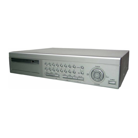
- Page 1 207Z HIGH-END SERIES The image shown above may differ from the actual product appearance. 715ZC, 717ZC / 715ZD, 717ZD / 715Z, 715Z_V1.7...
- Page 2 IMPORTANT SAFEGUARD CAUTION: To reduce the risk of electric shock, do not expose this apparatus to rain or moisture. Only operate this apparatus from the type of power source indicated on the label. The company shall not be liable for any damages arising out of any improper use, even if we have been advised of the possibility of such damages.
-
Page 3: Table Of Contents
TABLE OF CONTENTS 1. OVERVIEW ............................1 1.1 Product Description ..............................1 1.2 Features ................................. 1 Covert Recording ..............................1 1.3 Specification ................................2 1.4 Package Contents ..............................3 2. FRONT AND REAR PANELS ......................4 2.1 Front Panels................................4 2.2 Rear Panels ................................ - Page 4 6.4.10 Event Log..............................39 6.5 Search.................................. 39 6.6 Additional Operation ............................. 42 6.6.1 Key Lock and Unlock ..........................42 6.6.2 Switch NTSC / PAL System ........................42 6.6.3 Upgrade ..............................42 (1) Firmware / Multilanguage OSD Upgrade....................42 (2) AP and JAVA Software Upgrade ......................42 6.6.4 Audio Backup and Playback........................
-
Page 5: Overview
1. OVERVIEW 1.1 Product Description With the high storage capacity feature, this MPEG-4 DVR model is designed to accommodate up to 3 HDDs, or accommodate 2 HDDs and connect 1 independent disk array depending on your needs. To quickly backup, a CD or DVD writer (optional) and USB interface are built in for your choices except for network backup. -
Page 6: Specification
1.3 Specification SPECIFICATION 16CH Video System NTSC / PAL (switchable) Video Compression Format MPEG4 Video Input 8 Channels 16 Channels (Composite video signal 1 Vp-p 75Ω BNC) Video Loop Output 8 Channels 16 Channels (Composite video signal 1 Vp-p 75Ω BNC) Main Monitor Output: Composite video signal 1 Vp-p 75 BNC Video Output Call Monitor Output: Composite video signal 1 Vp-p 75 BNC... -
Page 7: Package Contents
SPECIFICATION 16CH Dwell Time (Sequential Channel Switch) Programmable with adjustable dwell time (2, 4, 8, 16 sec.) Alarm I/O 8 inputs, 1 output 16 inputs, 1 output Picture Zoom 2X digital zoom Key Lock Video Loss Detection Camera Title Support up to 6 letters Video Adjustable Hue / Color / Contrast / Brightness Date Display Format... -
Page 8: Front And Rear Panels
FRONT AND REAR PANELS 2. FRONT AND REAR PANELS 2.1 Front Panels ‧ 8CH ‧ 16CH LED Indication The following LEDs will be on when: POWER: DVR is powered on. STANDBY: DVR is powered off normally till the next time DVR is powered on. HDD: HDD is reading or under recording. - Page 9 FRONT AND REAR PANELS SLOW Under the playback mode, press “SLOW” button to slowly play the file. ZOOM Press “ZOOM” button to enlarge the image of the selected channel (under the live mode). / - 8CH: Press “ ” button to show the 4 / 8 / 9 channel display modes. 16CH: Press “...
-
Page 10: Rear Panels
FRONT AND REAR PANELS 2.2 Rear Panels ‧ 8CH MONITOR LOOP LOOP LOOP LOOP LOOP LOOP LOOP LOOP INPUT INPUT INPUT INPUT INPUT INPUT INPUT INPUT CALL RS 485 EXTERNAL I/O D / V DISK ARRAY LINK ACT. DC 19V 75 / HI-IMPEDANCE When using LOOP function, please switch to HI-IMPEDANCE. - Page 11 FRONT AND REAR PANELS ‧ 16CH MONITOR LOOP INPUT CALL 75Ω 75Ω HI-IMPEDANCE HI-IMPEDANCE RS 485 EXTERNAL I/O D / V DISK ARRAY LINK ACT. DC 19V 75 / HI-IMPEDANCE When using LOOP function, please switch to HI-IMPEDANCE. Otherwise, please switch to 75 . LOOP / INPUT (For channel 1~16) LOOP: Video output connector.
-
Page 12: Setup And Connections
BASIC OPERATION 3. SETUP AND CONNECTIONS 3.1 Install HDD The HDDs must be installed before the DVR is turned on. For detailed installation instructions, please refer to section "APPENDIX 1 INSTALL HDD" at page 72. Loosen the screws of the DVR upper cover and open the upper cover. Screw out the HDD bracket. -
Page 13: External Device Connections (Optional)
BASIC OPERATION 3.3 External Device Connections (Optional) 3.3.1 VGA Converter This optional peripheral (VGA Converter) allows your DVR to have VGA output function. For the connection method, please refer to the following figure as an example. For detailed connection methods, please refer to your VGA converter manual. -
Page 14: Power Setup
BASIC OPERATION 3.4 Power Setup This device should be operated only with the type of power source indicated on the manufacturer’s label. Connect the indicated AC power cord to the power adapter, and plug into an electrical outlet. “POWER” LED will be on as red. Press “POWER”... -
Page 15: Ddns Apply
BASIC OPERATION Install the supplied AP software on your NB/PC. Then, log into the DVR with the supplied AP software for the following default DVR settings. ‧ The DVR default IP address: 192.168.1.10 ‧ The DVR default account / password: admin ‧... - Page 16 BASIC OPERATION ‧ Enter all the information necessary for signing up an account according to the website instructions. ‧ Then, you will see the screen “Account Created”, and Dyndns will email the instructions to your specified E-mail address for enabling your account. You must complete the procedure according to the instructions in the mail. That is to must visit the confirmation address within 48 hours of the time that the e-mail was sent to complete the account creation process.
- Page 17 BASIC OPERATION ‧ Log in with your account information and click ”My Service”. ‧ Click ”Add Host Services”. ‧ Click ”Add Dynamic DNS Host”. ‧ Fill in and choose the desired host name. -13-...
-
Page 18: Dynamic Ip - Pppoe
BASIC OPERATION ‧ The host name is created. You will be connected to the corresponding IP address whenever you enter this hostname. 3.6.3 Dynamic IP - - - - PPPOE 1) Build a Local Area Network (LAN) between DVR and PC/NB with network cable: Your NB/PC and DVR must be under the same network domain to build the area network. -
Page 19: Dynamic Ip - Dhcp
BASIC OPERATION 4) Login your DVR via an Ethernet or dial-up network.: After setting up the network information of the DVR and connect it to the network, you can type DDNS host name, default user name and password in the supplied AP software login page to log into your DVR remotely. 3.6.4 Dynamic IP -... -
Page 20: Password And User Name Setting
BASIC OPERATION 3) After setting, please press “APPLY” button to confirm and finish the setting. 4) Login your DVR via an Ethernet or dial-up network: After setting up the network information of the DVR and connect it to the network, you can type DDNS host name and default user name and password in the supplied AP software login page to log into your DVR remotely. -
Page 21: Remote Login Password And User Name Setting
BASIC OPERATION 3.7.2 Remote Login Password and User Name Setting In the “SYSTEM CONFIG” “General” “Account” of the supplied AP software, you can set up user accounts (max. 5 accounts), password, life time, and authority level (max. 5 users on line at the same time) for remote login to the DVR. For detailed instructions, please refer to “(1) Account”... -
Page 22: Basic Operation
BASIC OPERATION 4. BASIC OPERATION 4.1 Recording This device offers three recording modes: manual record, event record and timer record. If the power is off accidentally, the recorded video data will not be lost and is safely stored in the HDD. The device will return to the original recording status after the power is on again. -
Page 23: Playback
BASIC OPERATION 4.2 Playback Press “PLAY” button on the front panel, and the device will display the last recorded video. Note: There must be at least 8192 images of recorded data for playback to work properly. If not, the device will stop playback. - Page 24 BASIC OPERATION Under the playback mode, you can select a channel to display the live video instead of the playback video. Step1: Press “Set” to highlight one channel. Step2: Press “UP“, “DOWN”, “LEFT”, “RIGHT” button to move the highlight to the channel you want to view the live video.
-
Page 25: Main Menu
MAIN MENU 5. MAIN MENU 5.1 Menu Tree -21-... -
Page 26: Menu Function
MENU FUNCTION 6. MENU FUNCTION 6.1 Record In this menu list, you can set record settings. Press “MENU” button on the front panel to enter the main menu list. The default admin password is 0000. Enter the default password, and press “ENTER”. Users can change the password later. Please refer to the section “6.4.6 System”... - Page 27 MENU FUNCTION 7) MANUAL RECORD IPS Select the images per second for MANUAL RECORD. The options are as following: NTSC 16CH FRAME 120, 60, 30, 15 FRAME 100, 50, 25, 12 480, 240, 120, 60 400, 200, 100, 50 FRAME 60, 30, 15, 7 FRAME 50, 25, 12, 6 240, 120, 60, 30...
-
Page 28: Timer
MENU FUNCTION 6.2 Timer In this menu list, you can schedule up to 7 sets of time for recording. Press “MENU” button on the front panel to enter the main menu list. Move the cursor to “TIMER”, and press ”ENTER”. The screen will show the following options. -
Page 29: Date
MENU FUNCTION 6.3 Date In this menu list, you can set up the system date and time for this device. Note: When the recording function is activated, please DO NOT change the date or time on your DVR. For details, please refer to the section “4.1 Recording” at page 18. Press “MENU”... -
Page 30: Advance
MENU FUNCTION 6.4 Advance In this menu list, you can set up more advanced functions according to your surveillance environment. For details, please check the description below. Press “MENU” button on the front panel to enter the main menu list. Move the cursor to “ADVANCE”, and press ”ENTER”. -
Page 31: Detection
MENU FUNCTION The submenu items are described below: 1) TITLE You can change the default camera naming here. The default title is the channel number. Move the cursor to the camera title you want to change, and press “ENTER” to access the character selection screen. Assign a new name to the camera up to six characters (letters or symbols). -
Page 32: Submenu Items Description
MENU FUNCTION The submenu items are described below: 1) TITLE Show the camera title of each channel set in “CAMERA”. 2) DET Select if you want to activate the motion detection function for the selected channel (ON/OFF). 3) AREA Press “ENTER” button to set the detection area. You will see similar screens as the following: Pink blocks represent the area that is not being detected while the transparent blocks are the area under detection. -
Page 33: Detection Timer
MENU FUNCTION 8) ALARM Select LOW / HIGH for the alarm polarity. The default alarm value is OFF. 9) PREV / NEXT (Only for 16CH model) Select “PREV” to go to the previous page, or “NEXT” to go to the next page. (2) Detection Timer Move the cursor to “DETECTION TIMER”, and press ”ENTER”. - Page 34 MENU FUNCTION PLAYBACK INFO Set the position where playback information will be indicated: CENTER or NORMAL (on the button of the left-hand side of the screen). DWELL DURATION (SEC) Set the duration time of each channel in second for CALL MONITOR (2 / 4 / 8 / 16). DE-INTERFACE Select to enable or disable “DE-INTERLACE”...
-
Page 35: Alert
MENU FUNCTION 6.4.4 Alert In this menu list, you can set alerts for different kinds of situations, such as when HDD is full. Move the cursor to “ALERT”, and press ”ENTER”. You will see a similar screen as the following: ADVANCE ALERT CAMERA... -
Page 36: Remote
MENU FUNCTION 6.4.5 Remote In this menu list, you can set up remote devices to work properly. Move the cursor to “REMOTE”, and press ”ENTER”. You will see a similar screen as the following: ADVANCE REMOTE CAMERA TITLE DEVICE PROTOCOL RATE DETECTION CAMERA... -
Page 37: System
MENU FUNCTION 6.4.6 System In this menu list, you can check or change some system settings. Move the cursor to “SYSTEM”, and press ”ENTER”. You will see a similar screen as the following: ADVANCE SYSTEM CAMERA SERIAL TYPE RS-485 DETECTION BAUD RATE 02400 DISPLAY... -
Page 38: Network
MENU FUNCTION Note: Do not disconnect the power of your DVR while the upgrade process is in progress, or the DVR functions may not work properly or be unable to use. R.E.T.R. (MIN) ‧ R.E.T.R. Activation Press “MENU” + “-” buttons on the front panel to enable R.E.T.R. function 3 / 5 / 10 minutes later. A message “R.E.T.R. - Page 39 MENU FUNCTION STATIC 160 . 121 . 346 . 236 GATEWAY 160 . 121 . 346 . 236 NETMASK 255 . 255 . 255 . 254 -35-...
-
Page 40: Backup
MENU FUNCTION ‧ PPPOE This PPPoE function needs to have one “username” and one “password” subscribed from one ISP supplier. For detailed PPPoE settings, please follow the AP (Licensed Software AP) setup, and then refer to the section “3.6.4 Dynamic IP - DHCP” at page 15, and “(1) DDNS” in section “7.5.1 Network” at page 54. ‧... - Page 41 MENU FUNCTION Move the cursor to “BACKUP”, and press ”ENTER”. You will see a similar screen as the following: BACKUP USB BACKUP USB BACKUP START TIME 2006 - 05 - 30 21 : 35 : 00 DISK BACKUP END TIME 2006 - 08 - 30 21 : 35 : 00 AVAILABLE SIZE 1.460 GB...
-
Page 42: Hdd Info
MENU FUNCTION Move the cursor to “BACKUP”, and press ”ENTER”. You will see a similar screen as the following: BACKUP DISK BACKUP USB BACKUP START TIME 2006 - 05 - 30 21 : 35 : 00 DISK BACKUP END TIME 2006 - 08 - 30 21 : 35 : 00 AVAILABLE SIZE 1.460 GB... -
Page 43: Event Log
MENU FUNCTION 6.4.10 Event Log In this menu list, you can view all the event information (event type, time and channel) or clear all log records. Move the cursor to “EVENT LOG”, and press ”ENTER”. You will see the following options: ADVANCE EVENT LOG CAMERA... - Page 44 MENU FUNCTION The submenu items are described below: 1) HDD-MASTER-1 Press “ENTER” to change to the HDD you want if there are more than 1 HDD in your DVR. 2) FULL LIST Show the time list for all types of the recorded files. The capital letters stand for the following: R: RECORD / S: SYSTEM / A: ALARM / MS: MOTION / T: TIMER.
- Page 45 MENU FUNCTION 8) TIME SEARCH Move the cursor to “TIME SEARCH”, and you will see a similar screen as the following: SEARCH TIME SEARCH HDD-MASTER-1 DATE 2006 - AUG - 31 15 : 12 : 03 FULL LIST SEARCH SELECTED RECORD LIST SYSTEM LIST ALARM LIST...
-
Page 46: Additional Operation
MENU FUNCTION 6.6 Additional Operation 6.6.1 Key Lock and Unlock ‧ Key Lock On: Press “REC” + “ENTER” buttons on the DVR front panel to lock keys. Please refer to the section “2.1 Front Panels” at page 4. ‧ AUTO KEYLOCK: Set the time-out after which the key lock function is activated (Never / 10 SEC / 30 SEC / 60 SEC). -
Page 47: Audio Backup And Playback
MENU FUNCTION Note: If the TCP port number is not 80, for example, IP address: 60.121.46.236, port number: 888, please key in “http://60.121.46.236:888” into the URL address box, and press “Enter”. ‧ Press “Download Java” button to go to JAVA website. ‧... - Page 48 MENU FUNCTION (2) Activate the R.E.T.R. Function: ‧ From DVR front panel: Press ”Menu” and “-” buttons on the DVR front panel at the same time. R.E.T.R. function will be activated 3 / 5 / 10 minutes later. For detailed instructions, please refer to section “6.4.6 System”. A message “R.E.T.R. ON” will be shown on the screen (in white text), and after the RETR function is activated, the message “R.E.T.R.”...
-
Page 49: Licensed Software Ap
LICENSED SOFTWARE AP 7. LICENSED SOFTWARE AP 7.1 Installation 1) Install the software: Place the attached licensed software AP disk into the CD drive or DVD drive, and install the application programs into your PC (Including AP and JAVA programs). After setup, users will see an AP shortcut icon on the desktop. For the latest software AP, please check with your distributor, or download from the Internet. - Page 50 LICENSED SOFTWARE AP 2) Search Search available DVR IP addresses in the local area network and modify the network setting of the DVR. See the example below: 3) Player Press this button to access and play the latest recorded file that are saved in your PC. 4) Copy Press this button to copy all the software installation files, so users can keep all the settings of the video web server for next software installation on other PCs.
-
Page 51: Control Panel
LICENSED SOFTWARE AP 7.3 Control Panel 7.3.1 DVR Control Panel a. Data Transfer Rate b. Image Transfer Rate Per Second c. Independent Channel Display Allow you to individually see the live view of a single channel without changing the main display setting. If you want to set a PTZ camera, simply press the channel connected to the PTZ camera and you can set the PTZ camera. - Page 52 LICENSED SOFTWARE AP g. Brightness/Contrast/Hue Press this button to show the following window and adjust the color display. h. Snapshot Press this button to take a snapshot of the image which will be saved in the specified destination set in “SYSTEM CONFIG”...
- Page 53 LICENSED SOFTWARE AP u. Sequence Press this button to enter the call monitor function, and press again to exit from the call monitor mode. When any motion is detected, the monitor will switch to the channel which is motion-triggered. v. Enter : Press this button to confirm the settings or enter your selection.
-
Page 54: Ptz Camera Control Panel
LICENSED SOFTWARE AP 7.3.2 PTZ Camera Control Panel To directly go into the PTZ control panel, press the Independent Channel Display icon (c) of the channel connected to a PTZ camera. Note: Make sure the device type of the channel connected to a PTZ camera is set correctly (i.e. PTZ) in “SYSTEM CONFIG”... -
Page 55: Playback Operation
LICENSED SOFTWARE AP r. Menu / Up / Down / Left / Right Press button to enter the PTZ menu / to confirm the selection and return to the upper menu / exit the menu mode. Press buttons to move the cursor and make the selection. s. -
Page 56: Convert The Recorded File To Avi Format
LICENSED SOFTWARE AP ‧Watermark : Proof the authenticity of the backup video. In the playback mode of the software AP, you can press this button to check the authenticity of the BACKUP VIDEO. If the BACKUP VIDEO had been altered, the video image will turn to light red and the playback will be paused. ‧Open Previous File : Open the previous backup video. -
Page 57: Network
LICENSED SOFTWARE AP 7.5.1 Network The network configuration allows the DVR to connect to an Ethernet network or dial-up network. PPPoE and DHCP network connection types are required to apply a DDNS service to get a “Hostname” to correspond to a dynamic IP address. -
Page 58: Ddns
LICENSED SOFTWARE AP ‧ `DHCP: This DHCP function needs to be supported by a router or cable modem network with DHCP services. Choose “DHCP” IP type. Then, select “Network” “DDNS” to set DDNS settings (see “(1) DDNS” at page 54 for details). When all the settings are completed, press “APPLY”. -
Page 59: Mail
LICENSED SOFTWARE AP (2) Mail If the e-mail notification function is activated, the DVR will send an e-mail notification to the specified recipients once alarm-trigger or motion-trigger recording happened. Please enable the function of e-mail notification in the “Alarm” menu first. -
Page 60: Dvr
LICENSED SOFTWARE AP 7.5.2 DVR Each camera channel can be adjusted independently. Select the desired camera channel and press “Edit” to enter the setting box. ‧ DVR-CAMERA Function: a. Title: Enter the camera channel name up to 6 characters. b. Adjustment: Adjust the BR (brightness) / CT (contrast) / ST (saturation) / HUE / COV / REC (recording) values of a camera. -
Page 61: Detection
LICENSED SOFTWARE AP (2) Detection Select the desired channel, and press “Edit” button to enter the motion detection sensitivity and area-setting page. ‧ The submenu items are described below: a. DETECT (motion detection): Select motion detection function ON / OFF. b. -
Page 62: Network Backup
LICENSED SOFTWARE AP (3) Network Backup You can backup the recorded data from the DVR directly to your PC and CD-R or DVD-R via the network. The backup file can be played directly in your PC via the supplied licensed AP, or via other media players (Ex: Windows Media Player or RealPlayer) after the file is converted to “AVI”... - Page 63 LICENSED SOFTWARE AP ‧ Making backup to a CD or DVD: (The instruction below use CD backup as an example) After pressing “Start”, “Write CD Setting” pop-up window will show on the screen. Choose “Close Disc” when you don’t want to write any more data to this CD after this burning; choose “Append Player” when you want to play the backup file on another PC which doesn’t have any available player to play it.
-
Page 64: Search List
LICENSED SOFTWARE AP c. Functions: (1) De-interlace (2) De-blocking (3) OSD (4) AVI Conversion (5) Config. Setting (6) Watermark (7) Open Previous (8) Open Next File d. Playback Control Buttons: Play / Stop / Pause / Fast Rewind / Fast Forward e. -
Page 65: Timer Record
LICENSED SOFTWARE AP (5) Timer Record In “DVR” “Timer Record”, you can schedule up to 7 sets of time for recording. Note: The same settings can also be made in the DVR. Please refer to the section “6.2 Timer” at page 24 for details. -
Page 66: Record Setting
LICENSED SOFTWARE AP 8) DATE Choose the current date from “DATE” drop-down menu and enter the current time. When you click the drop-down menu, a calendar shown for you to set the current date. 9) FORMAT Choose the format for date display from the three options: Y-M-D, D-M-Y and M-D-Y. 10) DAYLIGHT SAVING Specify whether to use daylight saving time (ON / OFF) and time period (START / END), and adjust the daylight saving time in hour (ADJUST). -
Page 67: Alarm
LICENSED SOFTWARE AP 16) RECORD QUALITY 4 options are available from the drop-down menu: BEST, HIGH, NORMAL and BASIC. 17) TOTAL IPS SHARE Choose the total IPS share as FIX or GROUP. The more IPS one channel gets, the more smoother the recorded video will be played. -
Page 68: Alarm List
LICENSED SOFTWARE AP (1) Alarm List In “Alarm” “Alarm List”, you can view the detailed information of alarm events (IP address, time & frame number), and see the following options: ‧ Path Display the location where all the alarm event data will be saved. This path is assigned in “General” “File Path”... -
Page 69: Account
LICENSED SOFTWARE AP ‧ Turbo step To speed up menu selection or the control of the PTZ camera under AP operations, users can activate "Turbo" function by selecting from the drop-down menu. Users are allowed to change the turbo steps from 1 to 30. Example: If the value of the turbo step is set to "5", it means that when users press one of the button up/down/left/right, one click is as clicking 5 times. - Page 70 LICENSED SOFTWARE AP ‧ To create a new account, press “ADD”, and you will see the setting window as the following: Item Description Username Set a user name what will be used at AP login page. Password Set a password what will be used at AP login page. Life time Select how long this account is allowed to stay online (1 Min / 5 Min / 10 Min / 1 Hour / 1 Day / INFINITY).
-
Page 71: Online User Info
LICENSED SOFTWARE AP (2) Online User Info In “General” “Online User Info”, you can view the current online user account information. This view can be updated by pressing “Info Refresh” button. (3) File Path In “General” “File Path”, you can view and change the file path for saving snapshots and recorded data, and customize the alarm audio file in “WMV”... -
Page 72: Operation Via Ie Browser
LICENSED SOFTWARE AP 7.6 Operation via IE Browser You can view the images or operate your DVR over the network with IE web browser. Please install the licensed software AP first. Note: The supported PC operation systems are Windows 2000 and Windows XP. Follow the steps below: Step 1: Key in the IP address used by your DVR in the URL address box, such as 60.121.46.236, and press Enter. - Page 73 LICENSED SOFTWARE AP Enter the user name and password, the same as the ones used at AP login. Press “Submit” when the user name and password are correct, or “Reset” to re-enter the user name and password. Step 4: You will see a similar screen as the following when the login information is correct. All the buttons and their functions on the control panel are the same as the ones on AP control panel except for the buttons indicated above.
-
Page 74: Troubleshooting
8. TROUBLESHOOTING 8.1 FAQ Please refer to the table below for easy troubleshooting. The table describes some typical problems and also their solutions. Please check them before calling your DVR dealer. Problem Solution No power Check power cord connection. Confirm that there is power supplied from the outlet. DVR is not working when pressing any button You might be under “Key Lock”... -
Page 75: Default Value
8.2 Default Value Item Default Value DVR Side ADMIN Password 0000 GUEST Password 1111 Camera - BRIG Camera - CONT Camera - SATU Camera - HUE Camera - COV Camera - REC Detection Detection - LS Detection - SS Detection - TS Detection - RE Detection - Alarm Network - IP Address... -
Page 76: Appendix 1 Install Hdd
APPENDIX 1 INSTALL HDD Carefully follow the steps below to ensure correct HDD installation. Note: The PCB side of the HDD must face upward, shown as the picture below. Step 1: Loosen the screws on the upper cover and open the upper cover of the DVR Step 2: Screw out the HDD bracket. -
Page 77: Appendix 2 Pin Configuration
APPENDIX 2 PIN CONFIGURATION When the magnetic contact is opened, the alarm will be triggered and the recording is on. At the same time, COM connects with NO and the siren with strobe starts wailing and flashing. NOTE: Please go to MENU -> ADVANCE -> DETECTION -> DETECTION SETUP, and set ALARM to LOW on the local machine. -
Page 78: Appendix 3 Rs-232 Protocol
APPENDIX 3 RS-232 PROTOCOL Use your PC keyboard to simulate your DVR keypad. Data: REMOTE PROTOCOL use 8 bit data, 1 start bit, 1 stop bit. FUNCTION STOP (FFH) (7FH) FUNCTION CODE ASCII FUNCTION CODE ASCII 0x4D 0x65 KEY_MENU KEY_DWELL 0x0D ENTER 0x31... -
Page 79: Appendix 4 Compatible Usb Flash Drive Brand
APPENDIX 4 COMPATIBLE USB FLASH DRIVE BRAND Please upgrade the firmware of the DVR to the latest version to ensure the accuracy of the following table. If the USB flash drive is not supported by the DVR, the "USB ERROR" message will be shown on the screen. Note: Please use your PC to format the USB flash drive as "FAT 32". -
Page 80: Appendix 5 Compatible Hdd Brand
APPENDIX 5 COMPATIBLE HDD BRAND Please upgrade the firmware of the DVR to the latest version to ensure the accuracy of the following table. Compatible HDD BRAND MANUFACTURER MODEL CAPACITY ROTATION Deskstar 7K250, HDS722516VLAT20 160GB 7200 rpm HDS722516VLAT80 160GB 7200 rpm HITACHI HDS722516DLAT80 160GB... -
Page 81: Index
INDEX Backup To CD or DVD At AP Side........ 58 Backup To PC At AP Side..........57 ADMIN Password Setting........16, 33 Backup Via CD or DVD Writer........36 Alarm Recording Duration ..........31 Backup Via USB Flash Drive........35 Alert Advance Setting ........... - Page 82 DVR Control Panel ............46 DVR Date and Time ............. 10 HDD Info Advance Setting..........37 DVR Date Setting ............25 HDD Installation ............71 DVR Detection Setup ........... 27 DVR Detection Timer............ 29 DVR ID Number ............33 Independent Disk Array Connection....... 9 DVR Keypad Simulation Via PC Keyboard....
- Page 83 Overwriting Mode ............18 Search Available IP At AP Side ........45 Setup and Connections ..........8 Package Contents ............3 Software AP Installation ..........44 PIN Configuration ............72 Specification ..............2 Play the latest recorded file At AP Side ......45 Static IP ............
Need help?
Do you have a question about the 715ZC and is the answer not in the manual?
Questions and answers